Page 265 of 302

Removing the wheel
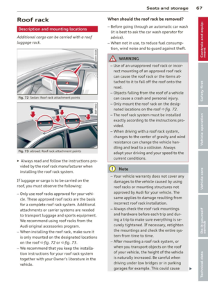
"' Remove the topmos t wheel bo lt completely
with the
he xagonal socket in t he screwdriv
er hand le (vehicle tool kit) ¢
fig. 207 and
set it aside on a
clean surface.
"' Screw the threaded end of the
alignment
pin
from the tool k it hand-tight into the
empty bolt hole ¢
fig. 208.
"' Then remove the o ther wheel bo lts as de
scribed above .
"' Take off the wheel leav ing the alignment
pin in the bo lt ho le
~ CD .
Putting on the spare tire
"' all road : Inflate the inflatable spare tire
~ page258
"' Push the spare tire over the a lignment pi n.
"' Screw o n the whee l bolts and tighten them
slightly using the hexagonal socket .
"' Remove the alignment pin and insert an d
t ighten the remaining whee l bo lt s light ly
li ke the rest .
"' Turn the jack handle counter-clockw ise to
lower the vehicle unt il the jack is f ully re
l eased .
"' Use the whee l bolt wrench to t ighten a ll
wheel bolts firmly ¢
page 261. Tighten
them
in a crisscross pattern, from one bo lt
to the (approx imately) opposi te o ne, to keep
t h e whee l cen te red .
"' Perform the steps requ ired after cha nging
the wheel ~
page 260 , After changing a
wheel .
The hex agonal so cket m akes it easier to re
move the w heel bo lts from the r im . Care
should be taken when removing the reversible
b lade .
@ Note
When removing or ins tall ing the wheel,
the rim could hit the brake rotor an d dam
age the rotor . Wor k carefully and have a
second person to he lp you .
@ Tips
-When mounting tires with unidirectional
tread design
ma ke s ure the tread pat-
What do I do now? 263
'
tern is po inted the righ t way
¢ page 263.
- The w heel bolts shou ld be clean an d easy
to t urn . Check fo r dirt an d corrosion on
the mating surfaces of both the w heel
and the hub. Remove all d irt from these
surfaces before remounting the whee l.
- Do not use the hexagonal socket in the
sc rewd river handle to loosen or t ighten
the whee l bolts.
Tires with unidirectional tread design
Tires with unidirectional tread design must be
mounted with their tread pattern pointed in the right direction.
Us ing a spa re tire with a tread pattern
intended for use in a specific di rection
When using a spare t ire with a tread patter n
intended for use in a spec ific d irection, please
note the following :
- The d irect ion of rotation is marked by an
ar
row on the side of the t ire .
-If the spare tire has to be insta lled in the in
correct d irect ion, use the spare tire only
temporarily s ince the tire will not be able to
achieve its optimum performance cha racte r
istics w it h regard to aquap la ni ng, no ise and
wear .
- We recommend that you pay part icu lar at
t en tion to th is fact during we t weather and
that you adjust your speed to match road
condi tions.
- Replace the flat t ire wi th a new one a nd
have it insta lled o n you r vehicle as soo n as
pos sible to res to re the hand ling advant ages
o f a u nidirec tional tire.
Notes on wheel changing
Please read t he info rmation ~ page 24 6, New
tires and replacing tires and wheels
if yo u a re
going to use a spare tire wh ich is different
from the tires on your vehicle.
After yo u change a tire:
IJI,-
•
•
Page 266 of 302

264 What do I do now?
-Check the tire pressure on the spare imme
diately after installation.
- Have the wheel bolt tightening torque
checked with a torque wrench as soon as possible by your authorized Audi dealer or
a qualified workshop.
- With steel and alloy wheel rims , the wheel
bolts are correctly tightened at a torque of
90 ft lbs . (120 Nm).
- If you notice that the wheel bolts are cor
roded and difficult to turn while changing
a tire, they should be replaced before you
check the tightening torque .
- Replace the flat tire with a new one and
have it installed on your vehicle as soon as
possible. Remount the wheel cover.
Until then, drive with extra care and at re
duced speeds .
A WARNING
-If you are going to equip y our veh icle
with t ires or rims w hich diffe r from t hose
w hich wer e facto ry ins talled, th en be
su re to read t he in forma tion ~
pag e 24 6,
N ew tir es and replacing tires and
wheel s.
- Always make su re the damaged w heel or
eve n a fla t tire and the ja ck and to ol kit
a re prop erly secure d in the lug gage com
par tment and are not loose in the pas
senger com partment .
- In an a cciden t or sud den m ane uver they
cou ld fly forwar d, inju ring anyone in the
vehicle.
- Always s tore d amage d w hee l, ja ck a nd
tool s secure ly in the lu g gage com part
me nt. Otherw ise, in an acc ident or sud
den maneuver they cou ld fly fo rward,
causing injury to passenge rs in the veh i
cle .
@ Note
Do not use commerc ia lly available t ire
sea lants. Othe rwise, the elect rical compo
ne nts of the tire pressure mon itor ing sys
tem* will no longer wo rk p roperly and the
sensor for th e tire p ressur e monito rin g system
* wi ll h ave to be repla ced by a
qu alified works ho p.
Page 267 of 302

Fuses and bulbs
Fuses
Replacing a fuse
Fuses that have blown will have metal strips
that have burned through.
Fig. 20 9 Left cockp it : fuse panel cover
The fuses are located at the front left and
r igh t of the cockpit and behi nd the trim on
the right side of the luggage compartment .
.. Turn off the ign it ion a nd the affected elec-
t rical consumers .
.. Check the following table to see which fuse
belongs to the consume r .
.. Remove the appropriate cover¢
fig. 209 or
¢page 218, fig. 180 .
.. To remove the purple plastic cl ip if necessa
ry
ll, hold onto it at the small s ide and pull
it out of the fuse panel¢
page 265,
fig. 210 .
.. Remove the clamp from the rear side of the
fuse cover ¢
fig. 209 .
.. Remove the fuse using the clamp and re
pla ce the blown fuse w ith an identical new
one.
& WARNING , -
Do not repair f uses and never replace a
blown fuse w ith one that has a higher amp
rating. This can cause damage to the e lec
trical system and a fire.
11 You can dis pos e of the plastic clip after removing it.
Fu se s and bulb s 265
(D Note
If a new fuse burns out again after short ly
have you have insta lled it, have the electri
ca l system checked by your authorized
Audi dealer .
{!) Tips
-The following table does not list fuse lo
cat ions that are not used .
- Some of the equipment items listed are
opt ional or only available on certa in
mode l configurations.
Left cockpit fuse assignment
Fi g. 21 0 Left cockpit: fuse panel wit h plastic clip
No. Consumer
Amps
Fuse panel @(black)
1 Dynamic steering 5
2 ES C control module 5
A/C system pressure sensor,
electromechanical parking
3
brake, Homelink, automatic
5 dimming interior rear view
mirror, air quality/outside
ai r sensor, ESC button
Page 268 of 302

266 Fuses and bulbs
No.
5 Sound actuator/exhaust
sound tuning
6 Headlight
range control sys-
tern/cornering light
7 Headlight (cornering light)
Control modules (electro-
mechanical parking brake,
8 shock absorber, quattro
I
sport, trailer hitch), DCDC
converter
9 Adaptive cruise control
10 Shift gate
11 Side assist
12 Headlight range control,
parking system
13 Airbag
14 Rear wiper (allroad)
15 Auxiliary fuse (instrument
panel)
16 Auxiliary fuse
terminal 15
(engine area)
Fuse panel @ (brown)
2 Brake light sensor
3 Fuel pump
4
5 Left seat heating with/with-
out seat ventilation
6 E5C
7 Horn
-Front left door (window reg·
8 ulator, central locking, mir-
ror, switch, lighting)
9 Wiper motor
10 ESC
Two-door models: rear left
window regulator, Four-door
11 models: rear left door (win-
dow regulator, central
lock-
ing, switch, lighting)
12 Rain and light sensor
Fuse panel © (red)
3 Lumbar support
Amps
5/15
5/7,5 7,5
5
5
5
5
5
5
15
10
40
5
25
5
15/30
5
15
30
30
25
30
5
10
No. Consumer
4 Dynamic steering
6
7
8
9
Interior lighting (Cabriolet)
Windshield washer system ,
headlight washer system
Vehicle electrical system
control module 1
Vehicle electrical system
control module 1 Left rear window regulator
motor (Cabriolet)/sunroof
10 Vehicle electrical system
control module 1
11 Right rear window regulator
(Cabriolet)/sun shade motor
12 Anti-theft
alarm warning
system
Right cockpit fuse assignment Amps
35
5
35
20
30
7,5/20
30
7,5/20
5
Fig. 211 R ight cockpi t: fuse pane l wit h plastic cl ip
No. Consumer Amps
Fuse panel @ (black)
5 Steering column switch
5
module
7 Terminal 15 diagnostic
con-
nector 5
•
....
Page 269 of 302

--No. Consumer Amps
I a
Gateway (Databus diagnos-
5 tic interface)
I
9 Supplementary heater
Fuse panel ® (brown )
1 CD/DVD playe r
2
Wi-Fi
3 MMI/Radio
4 Instrument cluster
5 Gateway (instrument cluster
control module)
6 Ignition lock
7 Light switch
8
Climate cont
rol system
blower
9 Steering column lock
10 Climate control system
11 Termina
l 30 diagnostic con-
nector
-
12 Steering column switch
module
Right luggage compartment fuse
assignment
5
5
5
5/20
5
5
5
5
40
5
10
10
5
F ig . 2 12 R igh t lu ggage compar tmen t: fu se pan el w ith
pla stic cl ip
-
Fu se s and bulb s 267
No . Consumer Amps
Fuse panel @ (blac k)
Luggage compartment lid
1 control module (all
road) /
30/10
Power top control module
(Cabriolet)
Trailer con trol modu le or re-
2 tractable rear spoiler (RS 5 15
Coupe)
3 Trailer control module 20
4 Trailer contro l modu le 20
5 Electromechanical parking
5
brake
6 E lectron ic damping con trol 15
7
Electromechanical parking
30
brake
8 R ear exterior lighting 30
9 quattro sport
35
10 Rear exterior lighting
30
11 Vehicle electrical system
20
con trol module
12 Term inal 30
5
Fuse panel © (brown )
1 Luggage compartment lid
30
control module (allroad)
-.
2 12-volt
socket, cigarette
20
lighter
3 DCDC converte
r path 1 40
4 DCDC converter path
2, DSP
30
amplifie r, radio
6
Right upper cabin heating
30
(Cabriolet)
7
Electromechanical parking
30
brake
R ig ht front door (window
9 regulator, central locking,
30
mirror, switch, lighting)
10 L
eft upper cabin heating
30
(Cabriole t)
Two-door models : rear r ight
window regu lator, Four-door
11 models : rear right door
30
(w indow regulato r, ce ntra l
l ock ing, switch , lighti ng)
Page 270 of 302

268 Fuses and bulbs
--No. Consumer Amps
12 Cell phone prep 5
-
Fuse panel© (black)
1 Right front seat heating 15
4 MMI 7,5
5
Radio 5
6 Rear view camera 5
7
Rear window heater (all·
30 road)
8 Rear Seat Entertainment 5
Bulbs
Replacing bulbs
For your safety, we recommend that you have
your authorized Audi dealer replace any bulbs for you.
It is becoming increasingly more and more
difficult to replace vehicle light bulbs since in many cases, other parts of the car must first
be removed before you are able to get to the
bu lb. Thi s applies especially to the light bu lbs
in the front of your car which you can only
reach through the engine compartment .
Sheet metal and bulb holders can have sharp
edges that can cause ser ious cuts, parts must
be correctly taken apart and then properly put
back together to help prevent breakage of
parts and long term damage from water that
can enter housings that have not been proper·
ly resealed.
F or your safety, we recommend that you have
your author ized Audi dealer replace any bulbs
for you, since your dealer has the proper tools,
the correct bu lbs and the expertise.
Ga s discharge lamps (Xenon lights}*:
Due to the high electrical vo ltage, have the
bu lbs rep laced by a qualified technician.
H eadlights with Xenon l ight are identified by
the high voltage sticker.
A WARNING
Changing Xenon lamps without the neces
sary equipment can cause serious personal
in jury.
- Bulbs are pressurized and can explode
when being changed. Potential risk of in
jury!
- On vehicles equipped with gas discharge
bulbs (Xenon light)* life-threatening in
juries can result from improper handling
of the high-voltage portions of such
lamps!
- Only your authorized Audi dealer or a
qualified workshop should change the
bu lbs in gas discharge lamps. There are
pa rts with sharp edges on the openings
and on the bulb holders that can cause
serious cuts. If you are uncertain about
what to do, have the work performed by
an author ized Audi dealer or other quali
fied workshop. Ser ious personal injury
may result from improperly performed
work.
(D Tips
- If you st ill prefer to replace the light
bulbs yourself, be aware that the engine
compartment is a hazardous area to
work in
9 page 213, Engine compart
ment
9 Lr:,. .
-It is best to ask your authorized Audi
dealer whenever you want to change a
bulb.
Page 271 of 302

Emergency situations
General
This chapter is intended for trained emer
gency crews and working personnel who
have the necessary tools and equipment to
perform these operations.
Starting by pushing or
towing
(D Note
Vehicles with an automatic transmission
cannot be started by pushing or towing .
Starting with jumper
cables
If necessary, the engine can be started by
connecting it to the battery of another vehi
cle.
If the engine should fail to start because of a
discharged or weak battery, the battery can be
connected to the battery of
another vehicle,
using a
pair of jumper cables to start the en
g ine.
Jumper cables
Use only jumper cables of sufficiently
largecross section to carry the starter current
safe ly. Refer to the manufacturer's specifica
tions.
Use only jumper cables with
insulated termi
na l clamps which are distinctly marked:
plus(+) cable in most cases colored red
minus(-) cable
in most cases colored black .
A WARNING
Batteries contain electricity, acid, and gas.
Any of these can cause very serious or fatal
injury. Follow the instructions below for
safe handling of your vehicle's battery.
- Always shield your eyes and avoid lean
ing over the battery whenever possible.
Emergency situations 269
-A discharged battery can freeze at tem
peratures just below 32 °F (0 °C). Before
connecting a jumper cable, you must
thaw the frozen battery completely, oth
erwise it could explode.
- Do not allow battery acid to contact eyes
or skin . Flush any contacted area with
water immediately .
- Improper use of a booster battery to
start a vehicle may cause an explosion.
- Vehicle batter ies generate explosive gas
es. Keep sparks, flame and lighted c iga
rettes away from batteries.
- Do not try to jump start any veh icle w ith
a low ac id level in the battery.
- The voltage of the booster battery must
also have a 12-Volt rating. The capacity
(Ah) of the booster battery should not be
lower than that of the discharged bat
tery. Use of batteries of diff erent voltage
or substantially different "Ah" rat ing
may cause an exp losion and personal in
jury.
- Never charge a frozen battery. Gas trap
ped in the ice may cause an explosion.
- Never charge or use a battery that has
been frozen . The battery case may have
be weakened.
- Use of batter ies of different voltage or
substantially different capacity (Ah) rat
ing may cause an exp losion and injury .
The ca pa city (Ah) of the booster battery
should not be lower than that of the dis
charged battery.
- Before you check anything in the engine
compartment, always read and heed all
WARNINGS¢
page 213, Engine com
partment.
(D Note
- App lying a higher voltage booster bat
tery will cause expensive damage to sen
sit ive electronic components, such as
control units, relays, rad io, etc .
- There must be no electrical contact be
tween the vehicles as otherwise current
could already start to flow as soon as the
posit ive(+) terminals are connected. ..,. •
•
Page 272 of 302

2 70 Emergency situations
@ Tips
The discharged battery must be properly
connected to the vehicle's electrical sys
tem. When jump starting or charging the
battery, never connect the negative
ground cable to the battery negative post
because the batte ry manager system must
be able to detect the battery 's state of
charge. Always connect the negative
ground cab le to the negative ground post
of the battery manager control unit.
Use of jumper cables
Make sure to connect the jumper cable
clamps in exactly the order described below!
Fig. 213 Engine compartment: Connecto rs fo r jum per
cables and charger
Fig. 214 Jump sta rting wi th the battery of anot her ve ·
h ide :@ booster battery, @ disc harged vehicle battery
The procedure described below for connecting
jumper cables is intended to provide a jump
start for your vehicle .
Vehicle with discharged battery:
.. Turn off lights and accessories, move lever
of automatic transmission to N (Neutral) or
P (Park) and set parking brake .
Connect POSITIVE(+) to POSITIVE(+)
(red)
.. Remove the cover above the jump start con
nection .
.. Open the
cover on the positive pole
¢fig. 213 .
1. Connect one end of the red positive cable
on the
jump start bolt c::> fig. 214 @
(Bolts under cover= "positive") of the ve
hicle to be started @.
2. Connect the other end to the positive ter-
minal @of the booster battery@.
Connect NEGATIVE (-) to NEGATIVE (-)
(black)
3. Connect one end of the b lack negative ca
ble to the negative terminal @of the
booster battery @.
4. Connect the other end to the
jump start
bolt @
(Bolts with hex head= "negative")
of the vehicle to be started @.
Starting the engine
.. Sta rt the engine of the vehicle with the
booster battery@. Run the engine at a
moderate speed.
.. Start engine with discharged vehicle battery
@ in the usual manner .
.. If the eng ine fails to start: do not keep the
starter cranking for longer than 10 seconds .
Wait for about 30 seconds and then try
again .
.. With engine running, remove jumper cables
from both vehicles in the exact
reverse or
der .
.. Close the
cover on the positive pole .
T he battery is vented to the outside to prevent
gases from entering the vehicle interior . Make
sure that the jumper clamps are well connect
ed with their
metal parts in full contact with
the battery terminals.
A WARNING
--
To avoid serious personal injury and dam
age to the veh icle, heed all warnings and
i nstructions of the jumper cable manufac-
turer . If in doubt, call for road service . ..,.