2012 SUBARU OUTBACK glove box
[x] Cancel search: glove boxPage 17 of 474

14
1) Shift lever (MT) (page 7-15)/Select lever(AT and CVT) (page 7-18)
2) Climate control (page 4-1)
3) Audio (page 5-1)
4) Navigation system (Refer to the Owner ’s
Manual supplement for the navigation system)
5) Multi function display (page 3-24)
6) Glove box (page 6-6)
7) Cup holder (page 6-8)
Page 68 of 474

1) Rear wheel house impact sensor (left-hand side)
2) Curtain airbag module (left-hand side)
3) Front door impact sensor (left-hand side)
4) Curtain airbag module (right-hand side)
5) Front passenger ’s occupant detection
control module
6) Center pillar impact sensor (left-hand side)
7) Seatbelt pretensioner (left-hand side)
8) Side airbag module (left-hand side)
9) Seatbelt buckle switch (right-hand side)
10) Rear wheel house impact sensor (right- hand side)
11) Side airbag module (right-hand side)
12) Seatbelt pretensioner (right-hand side)
13) Center pillar impact sensor (right-hand side)
14) Front passenger ’s occupant detection
system weight sensor
15) Front door impact sensor (right-hand side) &
SUBARU advanced frontal
airbag system, SRS side air-
bag and SRS curtain airbag
Your vehicle is equipped with a SUBARU
advanced frontal airbag system that com-
plies with the new advanced frontal airbag
requirements in the amended Federal
Motor Vehicle Safety Standard (FMVSS)
No. 208.
The SUBARU advanced frontal airbag
system automatically determines the de-
ployment force of the driver ’s SRS frontal
airbag at the time of deployment as well as
whether or not to activate the frontpassenger ’s SRS frontal airbag and, if
activated, the deployment force of the
SRS frontal airbag at the time of deploy-ment.
Your vehicle has warning labels on the driver ’s and front passenger ’s sun visors
beginning with the phrase “EVEN WITH
ADVANCED AIR BAGS ”and a tag
attached to the glove box lid beginning
with the phrase “Even with Advanced Air
Bags ”. Make sure that you carefully read
the instructions on the warning labels andtag.
Always wear your seatbelt. The SUBARU
advanced frontal airbag system is a
supplemental restraint system and must
be used in combination with a seatbelt. All occupants should wear a seatbelt or be
seated in an appropriate child restraintsystem.
For the locations of the driver
’s SRS
frontal airbag, front passenger ’sSRS
frontal airbag, SRS side airbag and SRS
curtain airbag, refer to “Components ”F 1-
42.
In a moderate to severe frontal collision,
the driver ’s and front passenger ’s SRS
frontal airbags deploy and supplement the
seatbelts by reducing the impact on thedriver ’s and front passenger ’s head and
chest.
Inamoderatetoseveresideimpact
collision, the SRS side airbag on the
impacted side of the vehicle deploys
between the occupant and the door panel
and supplements the seatbelt by reducing
the impact to the occupant ’s chest and
waist.
Inamoderatetoseveresideimpact
collision, the SRS curtain airbag on the
impacted side of the vehicle deploys
between the occupant and the side
window and supplements the seatbelt by
reducing the impact to the occupant ’s
head.
NOTE
The SRS side airbag, SRS curtain air-
bag and seatbelt pretensioner are not Seat, seatbelt and SRS airbags
1-45
– CONTINUED –
Page 91 of 474

2-2Keys and doors
Keys
1) Master key
2) Submaster key
3) Valet key
4) Key number plate
5) Security ID plate
Three types of keys are provided for your vehicle:
Master key, submaster key and valet key.
The master key and submaster key fit all
locks on your vehicle. . Ignition switch
. Driver ’s door
. Glove box
. Trunk lid (Legacy)
The valet key fits only the ignition switch and door locks. You can keep the trunk
and glove box locked when you leave your
vehicle and valet key at a parking facility.
CAUTION
Do not attach a large key holder or
key case to either key. If it bangs
against your knees while you are
driving, it could turn the ignition
switch from the “ON ”position to the
“ Acc ”or “LOCK ”position, thereby
stopping the engine.
& Key number
1) Key number plate
2) Security ID plate
The key number is stamped on the key number plate attached to the key set.
Write down the key number and keep it in
another safe place, not in the vehicle. This
number is needed to make a replacement
key if you lose your key or lock it inside thevehicle.
To make replacement keys, the security ID
is also needed. Refer to
“Key replace-
ment ”F 2-4.
Page 113 of 474

2-24Keys and doors
trunk lid down until the latch engages. NOTE . Do not leave your valuables in the
trunk when you leave your vehicle. . Even when the trunk lid cannot be
opened using the remote keyless entry
system, you can open the trunk lid by
using the key. Refer to “Trunk lid
(Legacy) –if the trunk lid cannot be
opened ”F 9-19.
& To open the trunk lid from inside
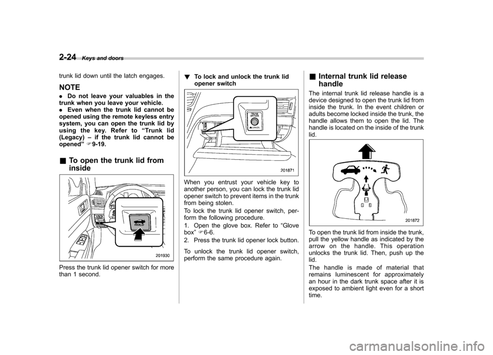
Press the trunk lid opener switch for more
than 1 second. !
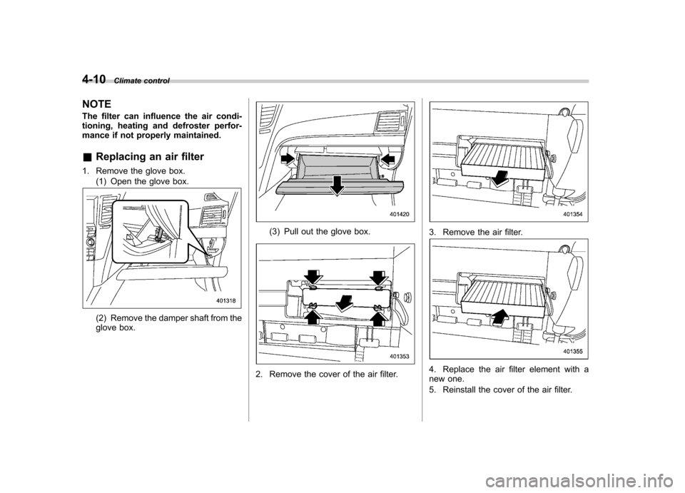
To lock and unlock the trunk lid
opener switch
When you entrust your vehicle key to
another person, you can lock the trunk lid
opener switch to prevent items in the trunk
from being stolen.
To lock the trunk lid opener switch, per-
form the following procedure.
1. Open the glove box. Refer to “Glove
box ”F 6-6.
2. Press the trunk lid opener lock button.
To unlock the trunk lid opener switch,
perform the same procedure again. &
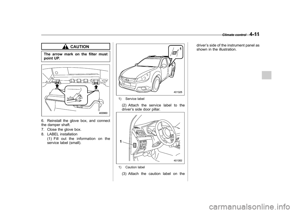
Internal trunk lid release handle
The internal trunk lid release handle is a
device designed to open the trunk lid from
inside the trunk. In the event children or
adults become locked inside the trunk, the
handle allows them to open the lid. The
handle is located on the inside of the trunklid.
To open the trunk lid from inside the trunk,
pull the yellow handle as indicated by the
arrow on the handle. This operation
unlocks the trunk lid. Then, push up thelid.
The handle is made of material that
remains luminescent for approximately
an hour in the dark trunk space after it is
exposed to ambient light even for a shorttime.
Page 181 of 474

4-10Climate control
NOTE
The filter can influence the air condi-
tioning, heating and defroster perfor-
mance if not properly maintained. & Replacing an air filter
1. Remove the glove box. (1) Open the glove box.
(2) Remove the damper shaft from the
glove box.
(3) Pull out the glove box.
2. Remove the cover of the air filter.
3. Remove the air filter.
4. Replace the air filter element with a
new one.
5. Reinstall the cover of the air filter.
Page 182 of 474

CAUTION
The arrow mark on the filter must
point UP.
6. Reinstall the glove box, and connect
the damper shaft.
7. Close the glove box.
8. LABEL installation (1) Fill out the information on the
service label (small).
1) Service label
(2) Attach the service label to the driver ’s side door pillar.
1) Caution label
(3) Attach the caution label on the driver
’s side of the instrument panel as
shown in the illustration. Climate control
4-11
Page 227 of 474

5-44Audio
NOTE . The Bluetooth
®audio function may
not operate properly under the follow-
ing conditions.
–The device is turned off.
– The battery of the device has run
down. – The device is not connected to
the system.– The device is behind the seat or
in the glove box.– A metal material is covering or
touching the device.
. Depending on the type of device that
is used, operation and sound volume
may be different from normal use of
those devices. . The sound quality may degrade due
to the influence of the device that is
connected to the system or the circum-
stances of the Bluetooth network. . When another Bluetooth
®device is
simultaneously connected, noise may
be heard. & Media format
Bluetooth
®audio devices cannot be
connected if they are not compatible with
the following Bluetooth
®profiles.
. A2DP (Advanced Audio Distribution
Profile) .
AVRCP (Audio/Video Remote Control
Profile)
& Setting Bluetooth
®audio
(type B audio)
1. Select “BT-A SETUP ”by pressing the
“ MENU ”button.
2. Perform the following procedure by
operating the “TUNE ”dial while “BT-A ”is
displayed.
NOTE
You cannot set Bluetooth
®audio while
driving. ! Registering (pairing) device
NOTE
Only one device can be registered.
1. Select the “PAIR AUDIO ”menu.
– If a device is already registered,
“ MEMORY FULL ”is displayed and the
mode changes to the Bluetooth
®
audio setting mode.
2. After the passkey is shown on the
display, input the passkey into the device. –If the registering procedure is fin-
ished, “PAIRED ”and the name of the
device are displayed. – If the registering procedure was not
successful, “FAILED ”is displayed. After the name of the device or
“FAILED ”
is displayed, the mode changes to the Bluetooth
®audio setting mode.
NOTE
After the ignition switch is turned to the “ LOCK ”position, the registered device
is not automatically connected to the
system even if the ignition switch is
turned to the “Acc ”or “ON ”position.
! Selecting device
1. Select the “SELECT AUDIO ”menu.
– If no devices are registered,
“ EMPTY ”is displayed and the mode
changes to the Bluetooth
®audio
setting mode.
2. Select the “CONFIRM ”menu.
– Then the name of the selected
device is displayed. – If the device is connected, “SE-
LECTED ”is displayed and the mode
changes to the Bluetooth
®audio
setting mode.– If the device cannot be connected,
“ FAILED ”is displayed and the select-
ing procedure was not successful.
! Setting passkey
1. Select the “SET PASSKEY ”menu.
– After the currently set passkey is
displayed, a new passkey can be
Page 232 of 474

Hands-free system (if equipped) NOTE .For models with the genuine
SUBARU navigation system, refer to
the Owner ’s Manual supplement for the
navigation system.. When selling your vehicle, make
sure that you initialize the Hands-free
system to prevent personal data from
being improperly accessed.
The Hands-free system operates while the
ignition switch is in the “Acc ”or “ON ”
position.
& Tips for the Hands-free sys- tem
! Bluetooth
®
It is possible to connect a cell phone to the
in-vehicle equipment through the Blue-
tooth
®format (wireless) to make a phone
call from the in-vehicle equipment or take
an incoming phone call.
Since the Bluetooth
®format is wireless, a
connection between the in-vehicle equip-
ment and the cell phone can be made
without placing them in close vicinity of
each other. The cell phone can be used
with it left in the breast pocket or bag. NOTE .
The Hands-free system may not
operate properly under the following conditions.
–The cell phone is turned off.
– The cell phone is not in the
phone call area. – The battery of the cell phone has
run down.– The cell phone is not connected
to the Hands-free system.– The cell phone is behind the seat
or in the glove box.– A metal material covers or
touches the cell phone.
. Depending on the type of cell phone
that is used, the screen on the cell
phone may remain illuminated while
the ignition switch is in the “ON ”
position. If this occurs, turn the illumi-
nation off by adjusting the cell phonesettings. . Depending on the setting of the cell
phone, the dial lock function may be
activated after making a call. Deacti-
vate the automatic dial lock function of
the cell phone before using the Hands-
free system. . Depending on the type of cell phone
that is used, operation and the sound
volume may be different from those of
cell phones currently used. .
When the ignition switch is turned to
the “LOCK ”position during a call, the
call may be disconnected or continued
on the cell phone depending on the
type of cell phone that is used. Note
that operation of the cell phone may be
necessary if the call is continued on the
cell phone. . Do not speak at the same time as the
other party during a call. If you and the
party speak at the same time, it may be
difficult for the other party to hear your
voice and vice versa. This is normal. . The receiver sound volume should
be set as low as possible. Otherwise,
the party you are calling may notice an
undesirable echo sound. . Speak clearly and loudly.
. Your voice may be difficult to be
heard by the party under the following conditions.
–Driving on a rough road.
– Driving at a high speed.
– Driving with a window open.
– When air from the ventilator
blows directly towards the micro-phone. – When the sound coming from the
ventilator is loud.– When the cell phone is too close
to the microphone. Audio
5-49
– CONTINUED –