2012 SUBARU OUTBACK warning light
[x] Cancel search: warning lightPage 139 of 474

3-20Instruments and controls
&All-Wheel Drive
warning light (AT and
CVT models)
WARNING
Continued driving with the AWD
warning light flashing can lead to
powertrain damage. If the AWD
warning light flashes, promptly park
in a safe place then check whether
all four tires are the same diameter
and whether any of the tires has a
puncture or has lost air pressure for
some other reason.
NOTE
If the temporary spare tire is used, the
AWD warning light may flash. Use of
the temporary spare tire should there-
fore be restricted to the minimum time
necessary. Replace the temporary
spare tire with a conventional tire as
soon as possible.
This light flashes if the vehicle is driven
with tires of different diameters fitted on its
wheels or with the air pressure exces-
sively low in any of its tires. &
Vehicle Dynamics
Control warning light/
Vehicle Dynamics Con-
trol operation indicatorlight
!Vehicle Dynamics Control warning light
CAUTION
The Vehicle Dynamics Control sys-
tem provides its ABS control
through the electrical circuit of the
ABS system. Accordingly, if the ABS
is inoperative, the Vehicle Dynamics
Control system becomes unable to
provide ABS control. As a result, the
Vehicle Dynamics Control system
becomes inoperative, causing the
warning light to illuminate. Although
both the Vehicle Dynamics Control
and ABS systems are inoperative in
this case, the ordinary functions of
the brake system are still available.
You will be safe while driving in this
condition, but drive carefully and
have your vehicle checked at a
SUBARU dealer as soon as possi-ble. NOTE .
If the electrical circuit of the Vehicle
Dynamics Control system itself mal-
functions, the warning light only illumi-
nates. At this time, the ABS (Anti-lock
Brake System) remains fully opera-tional.. The warning light illuminates when
the electronic control system of the
ABS/Vehicle Dynamics Control systemmalfunctions.
The Vehicle Dynamics Control system is
probably inoperative under any of the
following conditions. Have your vehicle
checked at a SUBARU dealer immedi-
ately. . The warning light does not illuminate
when the ignition switch is turned to the “ ON ”position.
. The warning light illuminates while the
vehicle is running. NOTE
If the warning light behavior is as
described in the following examples,
the Vehicle Dynamics Control system
may be considered normal. . The warning light illuminates right
after the engine is started but turns off
immediately and remains off.. The warning light illuminates after
the engine has started and turns off
Page 140 of 474

while the vehicle is subsequently being driven..The warning light illuminates during
driving, but turns off immediately and
remains off. ! Vehicle Dynamics Control opera-
tion indicator light
The indicator light flashes during activa-
tion of the skid suppression function and
during activation of the traction controlfunction. NOTE . The light may remain illuminated for
a short period of time after the engine
has been started, especially in cold
weather. This does not indicate the
existence of a problem. The light
should turn off as soon as the engine
has warmed up.. The indicator light illuminates when
the engine has developed a problem
and the CHECK ENGINE warning light/
malfunction indicator light is on.
The Vehicle Dynamics Control system is
probably malfunctioning under the follow-
ing condition. Have your vehicle checked
at a SUBARU dealer as soon as possible. . The light does not turn off even after
the lapse of several minutes (the engine
has warmed up) after the engine has started.
& Vehicle Dynamics
Control OFF indicatorlight
The light illuminates when the Vehicle
Dynamics Control OFF switch is pressed
to deactivate the Vehicle Dynamics Con-
trol system.
The Vehicle Dynamics Control system is
probably malfunctioning under any of the
following conditions. Have your vehicle
checked at a SUBARU dealer immedi-
ately. .The light does not illuminate when the
ignition switch is turned to the “ON ”
position.. The light does not turn off even after a
period of approximately 2 seconds after
the ignition switch has been turned to the“ ON ”position.
& Security indicator light
This indicator light shows the status of the
alarm system. It also indicates operation
of the immobilizer system. !Alarm system
It blinks to show the driver the operational
status of the alarm system. For detailed
information, refer to “Alarm system ”F 2- 15. !
Immobilizer system
This light blinks approximately 60 seconds
after the ignition switch is turned from“ ON ”position to the “Acc ”or “LOCK ”
position or immediately after the key is
pulled out. Refer to “Immobilizer ”F 2-3.
If the indicator light does not flash, it may
indicate that immobilizer system may be
malfunctioning. Contact your nearest
SUBARU dealer immediately.
In the event that an unauthorized key (for
example, an unauthorized duplicate) is
used, the security indicator light illumi-nates. NOTE
Even if the security indicator light
flashes irregularly or its fuse blows
(the light does not flash if its fuse is
blown), the immobilizer system will
function normally. Instruments and controls
3-21
– CONTINUED –
Page 142 of 474

&Cruise control indica-
tor light
This light illuminates when the “CRUISE ”
main switch is pressed to activate the
cruise control function. NOTE . If you press the main switch button
while turning the ignition switch “ON ”,
the cruise control function is deacti-
vated and the “CRUISE ”indicator light
flashes. To reactivate the cruise control
function, turn the ignition switch back
to the “Acc ”or “LOCK ”position, and
then turn it again to the “ON ”position.
. If this indicator light and the CHECK
ENGINE warning light/malfunction in-
dicator light flash simultaneously dur-
ing driving, have the vehicle checked
by your nearest SUBARU dealer.
& Cruise control set in-
dicator light
This light illuminates when vehicle speed
has been set to use the cruise controlfunction. &
Headlight indicator light
This indicator light illuminates under the
following conditions. .when the light switch is turned to the
“
” or “”position
. when the light switch is in the “AUTO ”
position and the headlights illuminate automatically & Front fog light indicator
light (if equipped)
This indicator light illuminates while the
front fog lights are illuminated. Clock NOTE
Your SUBARU dealer can change the
settings of activating/deactivating the
automatic adjustment of the clock by
the GPS (Global Positioning System)
(for models with the genuine SUBARU
navigation system). Contact your
SUBARU dealer for details.
The clock shows the time while the
ignition switch is in the
“Acc ”or “ON ”
position.
To adjust the time shown by the clock,
press the “+ ” button or the “� ” button. If
you press the “+ ” button, the indicated
time will change in one-minute incre-
ments. If you press the “� ” button, the
Instruments and controls
3-23
– CONTINUED –
Page 145 of 474

3-26Instruments and controls
NOTE . The indicated values vary in accor-
dance with changes in the vehicle ’s
running conditions. Also, the indicated
values may differ slightly from the
actual values and should thus be
treated only as a guide.. When either trip meter indication is
reset, the average fuel consumption
corresponding to that trip meter indica-
tion is not shown until the vehicle has
subsequently covered a distance of 1
mile (or 1 km). & Current fuel consumption
1) U.S. spec. models
2) Except U.S. spec. models
This indication shows the rate of fuel consumption at the present moment.
& Driving range on remaining fuel
1) U.S. spec. models
2) Except U.S. spec. models
The driving range indicates the distance
that can be driven taking into account the
amount of fuel remaining in the tank and
the average rate of fuel consumption.
When the low fuel warning light illumi-
nates, the driving range indication flashes
for 5 seconds. (The display first switches
to the driving range indication if it was
originally giving some other indication.)
1) U.S. spec. models
2) Except U.S. spec. models
If the driving range is shown as “
”,
there is only a tiny amount of fuel left in the
tank. You must refuel the vehicle immedi-
ately. NOTE
The driving range on remaining fuel is
only a guide. The indicated value may
differ from the actual driving range on
remaining fuel, so you must immedi-
ately fill the tank when the low fuel
warning light illuminates.
Page 147 of 474

3-28Instruments and controls
CAUTION
If any object is placed on or near the
sensor, the sensor may not detect
the level of the ambient light cor-
rectly and the auto on/off headlights
may not operate properly.
& High/low beam change (dimmer)
To change from low beam to high beam,
push the turn signal lever forward. When
the headlights are on high beam, the high
beam indicator light “
”on the combina-
tion meter is also on.
To switch back to low beam, pull the lever
back to the detent position. &
Headlight flasher
CAUTION
Do not hold the lever in the flashing
position for more than just a fewseconds.
To flash the headlights, pull the lever
toward you and then release it. The high
beam will stay on for as long as you hold
the lever. The headlight flasher works
even though the lighting switch is in the“ OFF ”position.
When the headlights are on high beam,
the high beam indicator light “
”on the
combination meter also illuminates. &
Daytime running light system
WARNING
The brightness of the illumination of
the high beam headlights is reduced
by the daytime running light system.
The light switch must always be
turned to the “
”position when it
is dark outside.
The high beam headlights will automati-
cally illuminate at reduced brightness
when the engine has started, under the
following conditions. . The parking brake is fully released.
. The light switch is in the “OFF ”or “
”
position. . The light switch is in the “AUTO ”
position and the headlights do not turn
on automatically. . The select lever is in a position other
than the “P ” position (AT and CVT mod-
els).
NOTE
When the light switch is in the “
”
position, the front side marker lights,
tail lights and license plate lights areilluminated.
Page 149 of 474

3-30Instruments and controls
Front fog light switch
(if equipped)
The front fog lights operate under the
following conditions. .when the light switch is in the “
”
position . when the light switch is in the “AUTO ”
position and the headlights turn on auto- matically
However, the front fog lights turn off when
the headlights are switched to high beam.
To turn on the front fog lights, turn the front
fog light switch on the turn signal lever
upward to the “
”position. To turn off the
front fog lights, turn the switch back down
to the “OFF ”position.
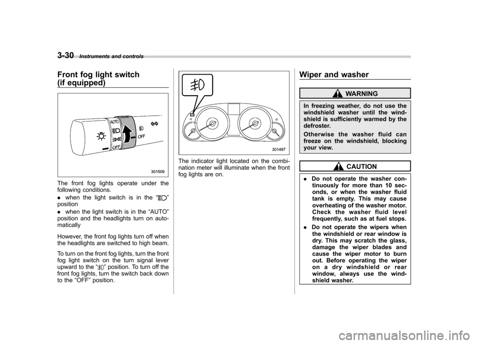
The indicator light located on the combi-
nation meter will illuminate when the front
fog lights are on. Wiper and washer
WARNING
In freezing weather, do not use the
windshield washer until the wind-
shield is sufficiently warmed by the
defroster.
Otherwise the washer fluid can
freeze on the windshield, blocking
your view.
CAUTION
. Do not operate the washer con-
tinuously for more than 10 sec-
onds, or when the washer fluid
tank is empty. This may cause
overheating of the washer motor.
Check the washer fluid level
frequently, such as at fuel stops.
. Do not operate the wipers when
the windshield or rear window is
dry. This may scratch the glass,
damage the wiper blades and
cause the wiper motor to burn
out. Before operating the wiper
on a dry windshield or rear
window, always use the wind-
shield washer.
Page 152 of 474

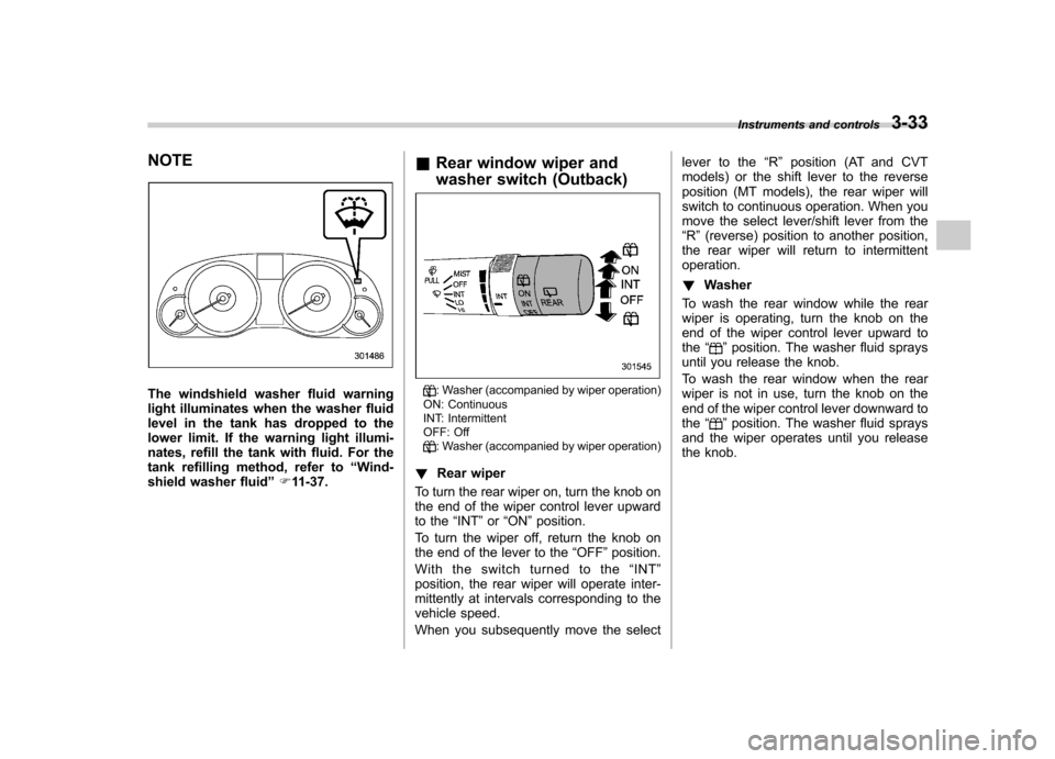
NOTE
The windshield washer fluid warning
light illuminates when the washer fluid
level in the tank has dropped to the
lower limit. If the warning light illumi-
nates, refill the tank with fluid. For the
tank refilling method, refer to“Wind-
shield washer fluid ”F 11-37. &
Rear window wiper and
washer switch (Outback): Washer (accompanied by wiper operation)
ON: Continuous
INT: Intermittent
OFF: Off
: Washer (accompanied by wiper operation)
! Rear wiper
To turn the rear wiper on, turn the knob on
the end of the wiper control lever upward
to the “INT ”or “ON ”position.
To turn the wiper off, return the knob on
the end of the lever to the “OFF ”position.
Withtheswitchturnedtothe “INT ”
position, the rear wiper will operate inter-
mittently at intervals corresponding to the
vehicle speed.
When you subsequently move the select lever to the
“R ” position (AT and CVT
models) or the shift lever to the reverse
position (MT models), the rear wiper will
switch to continuous operation. When you
move the select lever/shift lever from the“ R ”(reverse) position to another position,
the rear wiper will return to intermittentoperation. ! Washer
To wash the rear window while the rear
wiper is operating, turn the knob on the
end of the wiper control lever upward tothe “
”position. The washer fluid sprays
until you release the knob.
To wash the rear window when the rear
wiper is not in use, turn the knob on the
end of the wiper control lever downward tothe “
”position. The washer fluid sprays
and the wiper operates until you release
the knob. Instruments and controls
3-33
Page 158 of 474

!Compass calibration
1. For optimum calibration, switch off all
nonessential electrical accessories (rear
window defogger, heater/air conditioning
system, spotlight, etc.) and ensure all
doors are shut.
2. Drive to an open, level area away from
large metallic objects or structures and
make certain the ignition switch is in the“ ON ”position.
3. Press and hold the compass button for
6 to 9 seconds, and then release it. The
compass will enter the calibration mode,then “C ” and the direction will be dis-
played.
4. Drive slowly in a circle until “C ”
disappears from the display. Driving in
two or three circles might be necessary.
The compass is now calibrated.
5. Further calibration may be necessary
should outside influences cause the com-
pass to read inaccurately. You will notice
any outside influence if the compass tends
to read in only one particular direction.
Should you encounter this situation, return
to step 1 of the above procedure and
recalibrate the compass. !
HomeLink®Wireless Control Sys-
tem
The HomeLink
®Wireless Control System
can be used to activate remote control
devices such as gate operators, garage
door openers, door locks, home lighting
and security systems.
There are three HomeLink
®buttons on the
mirror, each of which can be programmed
for operation of one desired device. For
details on the device types which can be
operated by this system, consult theHomeLink
®website at:
www.homelink.com or call 1-800-355-3515.
Note the following information about this system.
Ifyourvehicleisequippedwiththe HomeLink
®Wireless Control System, it
complies with Part 15 of the Federal
Communications Commission Rules in
the U.S. and the RSS-210 of Industry
Canada in Canada. Its operation is subject
to the following two conditions:
(1) this device may not cause harmful
interference, and (2) this device must
accept any interference received, includ-
ing interference that may cause undesiredoperation.
Changes and modifications to this system by anyone other than an authorized
service facility could void authorization to
use this equipment. HomeLink
®and the HomeLink®house are
registered trademarks of Johnson Con-
trols, Inc.
WARNING
. When programming the
HomeLink
®Wireless Control Sys-
tem, you may be operating a
garage door opener or other
device. Make sure that people
and objects are out of the way
ofthegaragedoororother
device to prevent potential harm
or damage.
. Do not use the HomeLink
®Wire-
less Control System with a gar-
age door opener that lacks the
safety stop and reverse feature
as required by applicable safety
standards. A garage door opener
which cannot detect an object,
signaling the door to stop and
reverse, does not meet these
safety standards. Using a garage
door opener without these fea-
tures increases risk of serious
injury or death. For more infor-
mation, consult the HomeLink
®
Instruments and controls 3-39
– CONTINUED –