Page 766 of 828
01-96810-01
(3) Step 3
In this step, you can check the position and condition of the air source door and mode door. To
start step 3, turn the temperature control dial lightly toward the right and confirm that the number 3
appears on the display. It takes several tens of seconds to finish the check. If there is no fault
code, "30" is displayed. And if there is a malfunction, the corresponding fault code is added as
described in the step 2.
Turn temperature dial lightly toward
right to enter step 3 1.
System starts
sensor check after
"3" is displayed 2. Fault code for
sensor appears
and blinks (30 is
displayed when
there is no fault) 3.
Refer to the following table for the meaning of the fault code.
Page 767 of 828
01-10
In this step, the door position of each actuator, fan speed and operation of the compressor are
checked. To enter this step, turn the temperature dial to the right in the step 3. The number, "41",
appears on the display as soon as the step 4 is started. Press the defroster switch to change the
diagnosis mode.
(4) Step 4
Press
Press
Press
PressPress
Press
Turn temperature dial lightly
toward right to enter step 4 1.
Below table describes the detailed diagnosis items performed for each number. Check the
corresponding component for proper operation according to the table. The voltage values listed
in the table are the output voltage to operate the blower motor. The higher the voltage, the faster
the fan speed is.
Page 785 of 828

02-38810-01
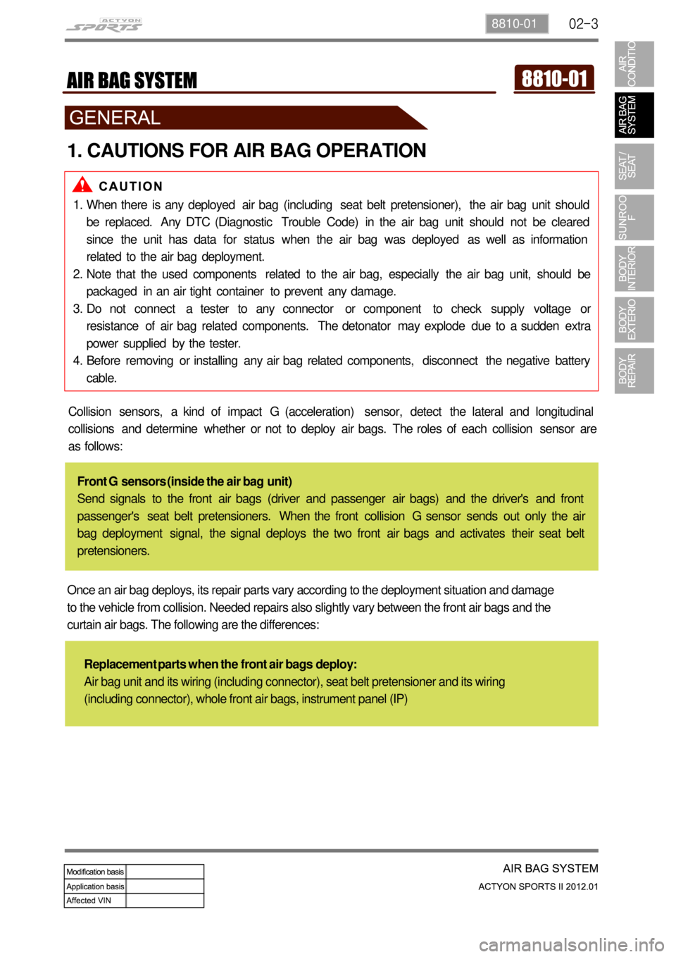
1. CAUTIONS FOR AIR BAG OPERATION
When there is any deployed air bag (including seat belt pretensioner), the air bag unit should
be replaced. Any DTC (Diagnostic Trouble Code) in the air bag unit should not be cleared
since the unit has data for status when the air bag was deployed as well as information
related to the air bag deployment.
Note that the used components related to the air bag, especially the air bag unit, should be
packaged in an air tight container to prevent any damage.
Do not connect a tester to any connector or component to check supply voltage or
resistance of air bag related components. The detonator may explode due to a sudden extra
power supplied by the tester.
Before removing or installing any air bag related components, disconnect the negative battery
cable. 1.
2.
3.
4.
Collision sensors, a kind of impact G (acceleration) sensor, detect the lateral and longitudinal
collisions and determine whether or not to deploy air bags. The roles of each collision sensor are
as follows:
Front G sensors (inside the air bag unit)
Send signals to the front air bags (driver and passenger air bags) and the driver's and front
passenger's seat belt pretensioners. When the front collision G sensor sends out only the air
bag deployment signal, the signal deploys the two front air bags and activates their seat belt
pretensioners.
Once an air bag deploys, its repair parts vary according to the deployment situation and damage
to the vehicle from collision. Needed repairs also slightly vary between the front air bags and the
curtain air bags. The following are the differences:
Replacement parts when the front air bags deploy:
Air bag unit and its wiring (including connector), seat belt pretensioner and its wiring
(including connector), whole front air bags, instrument panel (IP)
Page 816 of 828

04-37340-00
1. SPECIFICATIONS
2. CAUTIONS WHEN WORKING
Wear clean work clothes and gloves.
Replace and wash the gloves frequently.
Any unauthorized modification or operational test is not allowed since the sunroof motor and
control unit are preset at the factory.
Take care not to drop the sunroof assembly when removing it and do not keep it right up. 1.
2.
3.
4.
Operating voltage 9 ~ 16 V
Operating current (open & close) Max. 6 A
At no load Max. 2 A
Leakage current Max. 1 mA or less
Roof motor operating speed (at opening and closing)1.2 ± 0.5 sec./100 mm
Motor overload stop conditionsCurrent for up to 26 A and torque
(load) for up to 8.3 Nm
Opening amount230 ± 3
Vertical/horizontal tolerance for sunroof glass panel± 2 mm/± 2.5 mm
3. CAUTIONS FOR OPERATION
Even though the sunroof can be operated when the engine is not running, operating the
sunroof repeatedly with the engine turned off will run down the battery. Operate the sunroof
while the engine is running.
When the sunroof operation is completed, release the switch. Keeping pressing the switch can
result in malfunction.
Especially in winter, never operate the sunroof if operation areas are iced. Wait until melted.
Make sure that the sunroof is completely closed when leaving the vehicle. Leaving the vehicle
with the sunroof open result in a theft. In addition, rain or snow can get into the vehicle through
the open sunroof.
When the sunroof is fully open, wind buffeting symptom can be worse. In this case, try to
adjust the sunroof position manually or open the sunroof until the wind buffeting is disappeared
Parts of the body can be trapped in the sunroof and can be struck by passing objects. Do not
stick hands, head or anything else out of the openings.
Remove any dirt and foreign material stuck on the edge of the sunroof glass periodically.
Noise can occur due to friction when operating the sunroof. -
-
-
-
-
-