Page 679 of 1082

05-16
Indicator
(green)
Passenger seat belt reminder ▶
Left turn signal indicator ▶
Right turn signal indicator ▶
Indicator
(red)
Indicator
(green)
Indicator
(red)
Winter mode indicator(DSL only) ▶The right turn signal indicator blinks if the light switch is pushed up to the right,
and both turn signal indicators blink if the hazard warning flasher switch is
pressed.
When the mode switch is pressed, the winter mode is selected and the
winter mode indicator comes on on the instrument cluster. The winter
mode is used to start off on a slippery road with the 2nd gear. If the switch
is pressed again, the winter mode is deactivated and system returns to
standard mode.This indicator comes on when the ignition switch is turned to the "ON"
position and goes off when the passenger's seat belt is fastened.
The left turn signal indicator blinks if the light switch is pushed down to the
left, and both turn signal indicators blink if the hazard warning flasher switch
is pressed.
Smart key warning lamp ▶
Indicator
(amber)
This lamp comes on when the uncertified transponder or smart key is
detected,
SKM system is defective or there is no smart key in the vehicle.
Page 688 of 1082

05-258010-01
Operations for power supply in SVC ▶
When the ignition switch is turned to ON position, the message "WELCOME" is displayed for 2
seconds on the DOT LCD and the seat belt reminder comes on for 4 seconds. However, if a signal
with higher priority is received, the seat belt reminder comes on only for 2 seconds to display it.
The pre-warning (system check) indicator comes on for 4 seconds and goes off 0.4 seconds after
that the ignition is switched on.
All input signals can be input 4 seconds after the pre-warning (system check) indicator starts
illuminating.
Only the symbol and DOT LCD are illuminated initially, if the SKM (Smart Key Module) or door (B-
CAN) signal is received
while B+ power is supplied.
If the ignition is switched on with the LCD illuminated, the DOT LCD and the symbol follow
the side fascia panel.
When the step 1, 2 and 3 are performed after 4 seconds, the seat belt warning lamp is deactivated in
advance.
Dial light ON condition: Lights up gradually for 2 seconds when the ignition is switched on. 1.
2.
3.
4.
5.
6.
5) Illumination & Brightness
(1) Operations for Power Supply
Page 742 of 1082
06-318510-00
Multifunction wiper switches
2) Multifunction Switch
Multifunction light switches
Light switch
Front wiper switch
Wiper speed dial
Rear wiper switch Front fog lamp switch
Front auto washer switch The multifunction switch contains the auto washer and wiper switch, front fog lamp switch and auto
hazard warning flasher switch. For the vehicle with air bag, since the contact coil is fitted to the upper part
of the multifunction switch and ESP steering wheel angle sensor is fitted to upper part of the contact coil,
pay attention to when removing and fitting or checking the wiring.
Page 828 of 1082
01-18
A. Indicators on instrument cluster
C. HECU assembly
The HECU assemblies for ABS and ESP have
similar appearance but they have different inner
structure and connector connections from each
other. D. Front brake assembly
The disc brake for 4WD vehicle is the same with
the one for 2WD vehicle.
7. BRAKE SYSTEM AND ESP SYSTEM LAYOUT
B. Master cylinder assembly
Description for master cylinder in this chapter is
based on ABS/ESP equipped vehicle. For CBS,
there is an extra pressure valve mounted to the
master cylinder.
CaliperDisc
Parking brake
warning light
ABS warning lamp
ESP indicator
Page 849 of 1082
02-153680-01
This information is used by the TCU to decide which shift pattern to select and for shift energy
management. Electro-hydraulic solenoid valves and variable bleed solenoids control the transaxle gear
changes.
Six variable bleed solenoids and four on/off solenoids are used to direct transaxle fluid flow to control the
fluid pressure within the three clutches and two bands. Separate pressure regulators are used
exclusively for torque converter clutch control and main transaxle line pressure.
The TCU monitors all TCU inputs and outputs to confirm correct system operation. If a fault occurs the
TCU is able to perform default action and inform the driver of the problem through the instrument cluster
warning lights. Detailed information is available via trouble codes which can be read with the service tool.
Page 877 of 1082

03-173660-01
5. TRANSAXLE ELECTRONIC CONTROL SYSTEM
1) General Information
The transmission control unit (TCU) and its input/output network control the following transmission
operations:
Shift timing
Line pressure
Clutch pressure (shift feel)
Torque converter clutch -
-
-
-
also uses these signals when determining transaxle operating strategy. Using all of these input signals,
the TCU can determine when the time and conditions are right for a shift, or when to apply or release the
torque converter clutch. It will also determine the pressure needed to optimise shift feel.
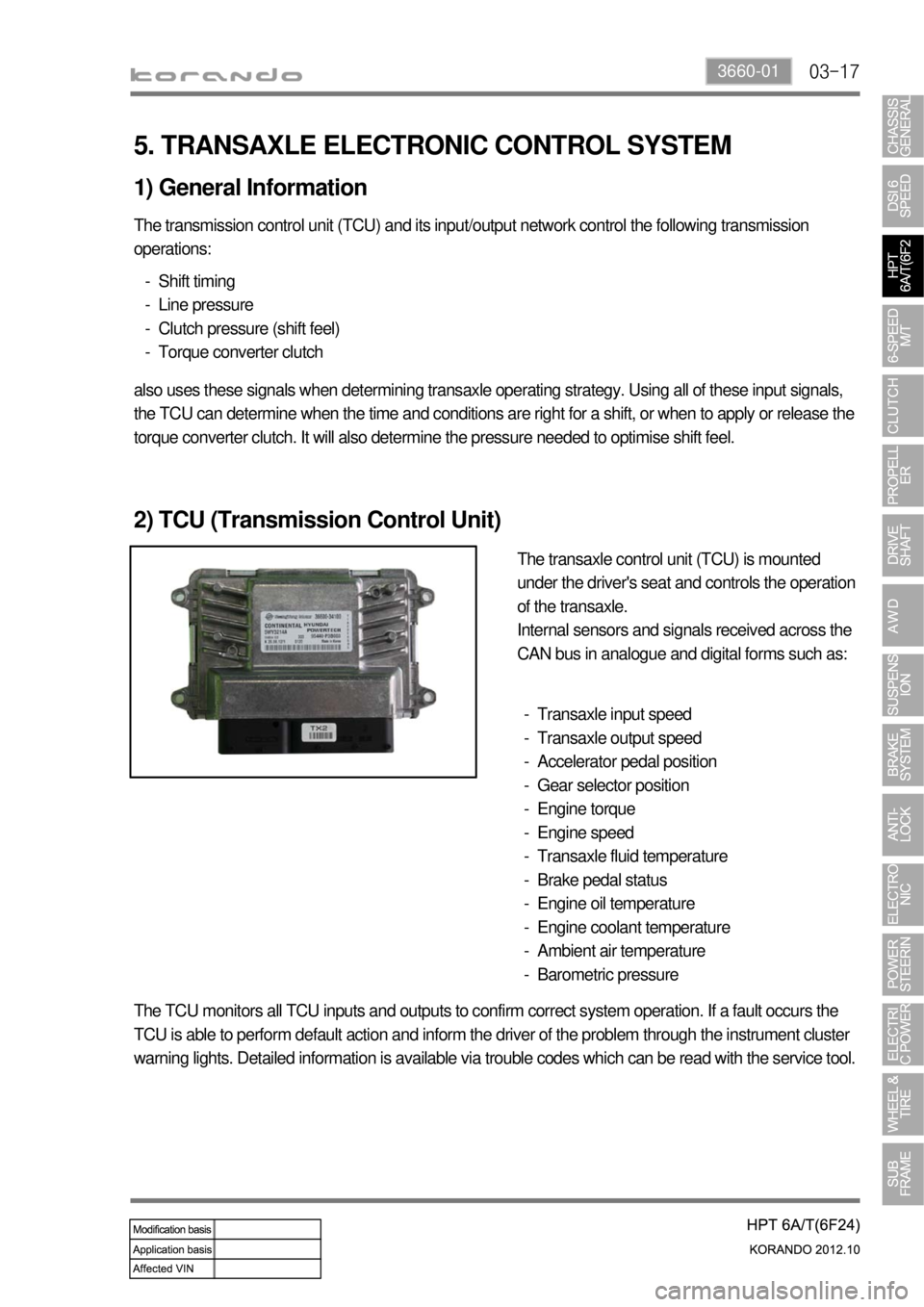
2) TCU (Transmission Control Unit)
The transaxle control unit (TCU) is mounted
under the driver's seat and controls the operation
of the transaxle.
Internal sensors and signals received across the
CAN bus in analogue and digital forms such as:
Transaxle input speed
Transaxle output speed
Accelerator pedal position
Gear selector position
Engine torque
Engine speed
Transaxle fluid temperature
Brake pedal status
Engine oil temperature
Engine coolant temperature
Ambient air temperature
Barometric pressure -
-
-
-
-
-
-
-
-
-
-
-
The TCU monitors all TCU inputs and outputs to confirm correct system operation. If a fault occurs the
TCU is able to perform default action and inform the driver of the problem through the instrument cluster
warning lights. Detailed information is available via trouble codes which can be read with the service tool.