Page 158 of 1082
03-230000-00
ENGINE CONTROL
SYSTEM
Engine ECU (D20DTF)
1. OVERVIEW
The components in the fuel system supply fuel and generate high pressure to inject fuel to each injector.
They are controlled by the engine ECU.
The common rail fuel injection system consists of fuel tank, fuel line, low pressure line which supplies lo
w
pressure fuel to the low pressure pump (includes high pressure pump), high pressure line which
connected to the injector and the engine control unit (ECU) which calculates the accelerator pedal
position and controls the overall performance of vehicle based on the input signals from various sensors.
HP fuel pump
Common rail and
Injector Fuel filter
(Priming pump)
Fuel supply tube
Fuel return tube
Fuel tank Fuel neck
Fuel sender (main)
Fuel sender (sub)
Low pressure line
High pressure line
Page 159 of 1082
03-24
Fuel rail assembly
Relieves the pulsation.
Measures the fuel pressure.
Distributes the fuel to injectors.Camshaft position sensor
Determines the injection order.
Injector (C3I)
Pre-injection, main injection, after-injection by
signals from ECU
Fuel tank
Fuel metering by dual sender. Supply the fuel in
main fuel tank and sub fuel tank through fuel
inlet tube
2. SYSTEM LAYOUT AND OPERATION
1) Layout
Fuel supply line
Fuel return line
For sensor and actuator control logic,
refer to Chapter "ENGINE CONTROL".
Page 161 of 1082

03-26
2) Fuel System Flow Diagram
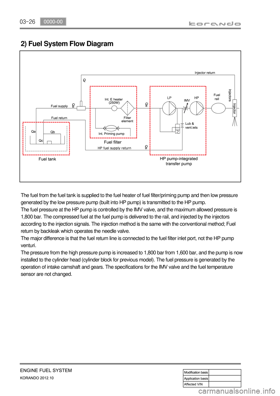
The fuel from the fuel tank is supplied to the fuel heater of fuel filter/priming pump and then low pressure
generated by the low pressure pump (built into HP pump) is transmitted to the HP pump.
The fuel pressure at the HP pump is controlled by the IMV valve, and the maximum allowed pressure is
1,800 bar. The compressed fuel at the fuel pump is delivered to the rail, and injected by the injectors
according to the injection signals. The injection method is the same with the conventional method; Fuel
return by backleak which operates the needle valve.
The major difference is that the fuel return line is connected to the fuel filter inlet port, not the HP pump
venturi.
The pressure from the high pressure pump is increased to 1,800 bar from 1,600 bar, and the pump is now
installed to the cylinder head (cylinder block for previous model). The fuel pressure is generated by the
operation of intake camshaft and gears. The specifications for the IMV valve and the fuel temperature
sensor are not changed.
Page 169 of 1082
04-6
1. OVERVIEW
The intake system for D20DTF engine is equipped with an electric throttle body which includes a flap.
This flap is controlled by an electrical signal to cut off the intake air entering to the engine when the
ignition switch is turned off. To be sure to get the optimized swirl in intake manifold, the swirl valve and
dual type port have been adopted. And, the improved HFM sensor has been adopted to control the
intake air volume more precisely.
2. COMPONENTS
1719-02 Swirl control valve
Operates variably in accordance with the engine
load and rpm.
* For more information, refer to Chapter "Engine
Control".
1719-01 Intake manifold
Passage for intake air during the operation of
variable swirl valve
1719-16 Electric throttle body
* For more information, refer to Chapter "Engine
Control".
2330-01 Intercooler assembly
Page 202 of 1082
07-50000-00
1. SYSTEM DESCRIPTION
1) Overview
The lubrication system supplies oil to each lubrication section to prevent friction and wear and to remove
heat from the friction part. As the engine runs, frictional heat is generated on each lubrication section. If
this condition persists, the bearing can be burned and stuck.
In other words, it creates an oil film on each sliding surface to convert solid friction to liquid friction in
order to minimize wear and prevent temperature increasing on the friction part.
For the D20DTF engine with no oil pressure switch, the engine ECU receives the low engine oil level
signal from the oil level sensor and communicates with the instrument cluster through the CAN
communication to turn on the warning lamp.
2) Component
Oil level sensorEngine oil dipstick
Oil panOil pumpOil filter module
Oil cooler
Page 238 of 1082
10-14
When there is no engine cranking signal after turning the ignition key ON ▶
Page 242 of 1082

11-6
2. OPERATING PROCESS
1) System Layout
(1) Engine start
SKM performs the authentication process for the SMART key and sends the engine start request to
EMS if there is a normally coded SMART key when pressing the Engine Start/Stop button with the
<0089009900880092008c00470097008c008b008800930047008b008c00970099008c009a009a008c008b004700880095008b0047008e008c008800990047009a008f0090008d009b00470093008c009d008c0099004700900095004702c8007702c9004700
960099004702c8007502c9004700970096009a0090009b0090>on.
SKM sends the start request signal to PCAN network and the cranking request to BCAN network by
“SMART key location” signal when receiving the engine start signal by Engine Start/Stop
button.
SKM turns off the IGN2/ACC relay during cranking to shut down the electric loads.
SKM receives the starting status signal from EMS throug PCAN.
<0068008d009b008c00990047008a009900880095009200900095008e00530047007a007200740047009b009c00990095009a0047009600950047009b008f008c00470068006a006a00560070006e0075005900470099008c0093008800a000470088009500
8b0047009a008c0095008b009a0047009b008f008c00470097>ower status signal of “IGN
after started” through BCAN.
EMS starts to crank the engine after checking the pre-heating condition if it receives the engine
cranking request 1 when pressing the Engine Start/Stop button. EMS starts to crank the engine
immediately if it receives the engine cranking request 2 when pressing the Engine Start/Stop button. 1.
2.
3.
4.
5.
6.
Engine cranking request 1: when pressing the Engine Start/Stop button shortly in normal
conditions
Engine cranking request 2: when pressing the Engine Start/Stop button again after first press or
when pressing the Engine Start/Stp button for more than 3 seconds -
-
Engine start during driving 7.
When pressing the Engine Start/Stop button with IGN ON, the engine start is requested if the
<009d008c008f0090008a0093008c0047009a0097008c008c008b00470090009a00470093008c009a009a0047009b008f008800950047005800570047009200940056008f0047009600990047009500960047009a0090008e00950088009300530047009b00
8f008c0047008e008c008800990047009a008f0090008d009b> lever is in ‘N” position and
the brake switch is ON (no need authentication for 30 seconds).
When pressing the Engine Start/Stop button with IGN ON, the engine start is requested
regardless of brake signal if the vehicle s
p<008c008c008b00470090009a00470096009d008c00990047005800570047009200940056008f004700880095008b0047009b008f008c0047008e008c008800990047009a008f0090008d009b00470093008c009d008c009900470090009a00470090009500
47>‘
position (no need authentication for 30 seconds).
Except input of brake switch signal
In vehicle equipped with A/T, when pressing the Engine Start/Stop button for more than 10
seconds with ACC ON, the engine start is requested regardless of brake signal if the gear shift
lever is in “P” or ‘N” position in IGN ON. -
-
*
-
Page 260 of 1082

12-138530-00
Do not move the shift lever to Neutral position while driving with the cruise control turned on.
Otherwise, it may result in system malfunction or accidents.
Always be prepared to use the brake or accelerator pedal for safe driving while the cruise control
system is running.
The actual speed can be different from the set speed momentarily when driving on a uphill or
downhill. So, it is recommended to disable the cruise control function on a uphill or downhill. hen
driving on a steep hill use the engine brake and foot brake properly to protect the vehicle system
and for a safe driving.
Ensure that the safe distance is maintained and use the brake pedal if needed. 1.
2.
3.
4.
(1) Abnormal Cancellation of the Cruise Control
Sharp acceleration or deceleration
- 50 km/h faster than set speed
- 25 km/h faster than set speed for one minute
- 70 km/h slower than set speed
- 65 km/h slower than set speed for 3 minutes
When the cruise control lever is faulty.
When the brake switch and the brake light switch input signal are implausible. 1.
2.
3.
When the cruise control function is cancelled abnormally or intermittent problems occur, stop the vehicle
and turn off the ignition switch and remove the key to reset the system. After a while, turn on the ignition
switch again to operate the cruise control system.