Page 129 of 228
 because they are more
likely to become punctured or damaged by
road debris, potholes etc.
Do not overload the tires by exceeding the
specifi")
stopping distance, and result in sudden
deflation (blowout) because they are more
likely to become punctured or damaged by
road debris, potholes etc.
Do not overload the tires by exceeding the
specified load limit as indicated on the
Tire and Loading Information placard on
the
driver’s door B‑pillar. Overloading the
tires can overheat them, possibly causing
a blowout. Overloading the tires can also
result in handling or steering problems, or
brake failure.
Check the tire inflation pressure at least
once a month.
Check and adjust the tire inflation
pressure when the tires are cold
(Y page 125).
Checking tire inflation pressure
manually Follow the steps below to achieve correct
tire inflation pressure:
X
Remove the cap from the valve on one tire.
X Firmly press a tire gauge onto the valve.
X Read the tire inflation pressure on tire
gauge and check against the
recommended tire inflation pressure on
the Tire and Loading Information
placard on the driver’s door B‑pillar
(Y page 130). If necessary, add air to
achieve the recommended tire inflation
pressure.
X If you have overfilled the tire, release
tire inflation pressure by pushing the
metal
stem of the valve with e.g. a tip of
a pen. Then recheck the tire inflation
pressure with the tire gauge.
X Install the valve cap.
X Repeat this procedure for each tire.
Tire Pressure Monitoring System (TPMS)* Your vehicle may be equipped with a Tire
Pressure
Monitoring System (TPMS). It monitors the tire inflation pressure in
all
four tires. A warning is issued to alert
you to a decrease in pressure in one or more
of the tires.
The Tire Pressure Monitoring System
(TPMS) is equipped with a combination low
tire pressure/TPMS malfunction telltale in
the instrument cluster. Depending on how
the telltale illuminates, it indicates a low
tire pressure condition or a malfunction in
the TPMS system itself:
R If the telltale illuminates continuously,
one or more of your tires is significantly
underinflated. There is no malfunction
in the TPMS.
R If the telltale flashes for 60 seconds and
then stays illuminated, the TPMS system
itself is not operating properly.
The TPMS only functions on wheels that are
equipped with the proper electronic
sensors. G
WARNING
The TPMS does not indicate a warning for
wrongly selected inflation pressures.
Always adjust tire inflation pressure
according to the Tire and Loading
Information placard on the driver’s door
B‑pillar.
The
TPMS is not able to issue a warning due
to a sudden dramatic loss of pressure (e.g.
tire blowout caused by a foreign object). In
this case bring the vehicle to a halt by
carefully applying the brakes and avoiding
abrupt steering maneuvers. G
WARNING
Each tire should be checked monthly when
cold
and inflated to the inflation pressure
recommended by the vehicle manufacturer
on the Tire and Loading Information
placard. If your vehicle has tires of a
different size than the size indicated on
the Tire and Loading Information placard,
you should determine the proper tire
inflation pressure for those tires. Tires and wheels
127
>> Operation.
* optional Z
Page 130 of 228
 that illuminates
a low tire pressure telltale when one or
more of your tires is significantly
u")
As an added safety feature, your vehicle has
been equipped with a tire pressure
monitoring system (TPMS) that illuminates
a low tire pressure telltale when one or
more of your tires is significantly
underinflated.
Accordingly, when the low tire pressure
telltale illuminates, you should stop and
check your tires as soon as possible, and
inflate them to the proper pressure.
Driving on a significantly underinflated
tire
causes the tire to overheat and can lead
to tire failure.
Underinflation also reduces fuel
efficiency and tire tread life, and may
affect the vehicle’s handling and stopping
ability. Please note that the TPMS is not a
substitute for proper tire maintenance,
and it is the driver’s responsibility to
maintain correct tire pressure, even if
underinflation has not reached the level to
trigger illumination of the TPMS low tire
pressure telltale.
Your vehicle has also been equipped with a
TPMS malfunction indicator to indicate
when the system is not operating properly.
The TPMS malfunction indicator is
combined with the low tire pressure
telltale. When the system detects a
malfunction, the telltale will flash for
approximately 1 minute and then remain
continuously illuminated.
This sequence will continue upon
subsequent vehicle start-ups as long as the
malfunction exists. When the malfunction
indicator is illuminated, the system may
not be able to detect or signal low tire
pressure as intended.
TPMS malfunctions may occur for a variety
of reasons, including the installation of
incompatible replacement or alternate
tires or wheels on the vehicle that prevent
the TPMS from functioning properly. Always
check the TPMS malfunction telltale after
replacing one or more tires or wheels on
your vehicle to ensure that the replacement or alternate tires and wheels allow the
TPMS to continue to function properly.
i If a condition causing the TPMS to
malfunction develops, it may take up to
10 minutes for the system to signal a
malfunction using the TPMS telltale
flashing and illumination sequence.
The telltale extinguishes after a few
minutes driving if the malfunction has
been corrected.
i Operating radio transmission
equipment (e.g. wireless headsets, two-
way radios) in or near the vehicle could
cause the TPMS to malfunction.
i USA only:
This device complies with Part 15 of the
FCC Rules. Operation is subject to the
following two conditions:
R This device may not cause harmful
interference, and
R this device must accept any
interference received, including
interference
that may cause undesired
operation.
Any unauthorized modification to this
device could void the user’s authority to
operate the equipment.
i Canada only:
This device complies with RSS‑210 of
Industry Canada. Operation is subject to
the following two conditions:
R This device may not cause
interference, and
R this device must accept any
interference received, including
interference that may cause undesired
operation of the device.
Any unauthorized modification to this
device could void the user’s authority to
operate the equipment. 128
Tires and wheels
>> Operation.
Page 131 of 228

Restarting the TPMS
G
WARNING
It is the driver’s responsibility to
calibrate the TPMS on the recommended
cold inflation pressure. Underinflated
tires affect the ability to steer or brake
and might cause you to lose control of the
vehicle.
When you restart the TPMS, the system sets
new reference values for each tire.
The TPMS must be restarted when you have
adjusted the tire inflation pressure to a
new
level (e.g. because of different load or
driving conditions). The TPMS is then
recalibrated to the current tire inflation
pressures.
X Using the Tire and Loading Information
placard on the driver’s door B‑pillar
(Y page 130), make sure the tire
inflation pressure of all four tires is
correct.
i Restart the TPMS after adjusting the
tire inflation pressure to the inflation
pressure recommended for the vehicle
operating condition. Tire pressure
should only be adjusted on cold tires.
Observe the recommended tire inflation
pressure on the Tire and Loading
Information
placard on the driver’s door
B‑pillar (Y page 130). X
Press Restarting TPMS button :.
The
combination low tire pressure/TPMS
malfunction telltale in the instrument
cluster (Y page 22) flashes for approximately 5 seconds and then goes
out.
After driving a few minutes the system
verifies that the current tire inflation
pressures are within the system’s
specified range. Afterwards the current
tire inflation pressures are accepted as
reference pressures and then monitored. Maximum tire inflation pressure
G
WARNING
Never exceed the max. tire inflation
pressure. Follow recommended tire
inflation pressures.
Do not underinflate tires. Underinflated
tires wear excessively and/or unevenly,
adversely affect handling and fuel
economy, and are more likely to fail from
being overheated.
Do not overinflate tires. Overinflated
tires can adversely affect handling and
ride comfort, wear unevenly, increase
stopping distance, and result in sudden
deflation (blowout) because they are more
likely to become punctured or damaged by
road debris, potholes etc. i
For illustration purposes only. Actual
data
on tires are specific to each vehicle
and may vary from data shown in above
illustration.
This is the maximum permissible tire
inflation pressure : for the tire. Tires and wheels
129
>> Operation. Z
Page 132 of 228
 for proper
tire inflation. Loading the vehicle
Two labels on your vehicle show how much
weight it may properly carry.
1) The Tire an")
Always follow the recommended tire
inflation pressure (
Y page 125) for proper
tire inflation. Loading the vehicle
Two labels on your vehicle show how much
weight it may properly carry.
1) The Tire and Loading Information placard can be found on the driver’s
door B‑pillar. This placard tells you
important information about the
number of people that can be in the
vehicle
and the total weight that can be
carried in the vehicle. It also contains
information on the proper size and
recommended tire inflation pressures
for the original equipment tires on
your vehicle.
2) The certification label, also found on the driver’s door B‑pillar, tells you
about
the gross weight capacity of your
vehicle, called the Gross Vehicle
Weight Rating (GVWR). The GVWR
includes the weight of the vehicle, all
occupants, fuel and cargo. The
certification label also tells you about
the front and rear axle weight capacity,
called the Gross Axle Weight Rating
(GAWR). The GAWR is the total allowable
weight that can be carried by a single
axle (front or rear). Never exceed the
GVWR or GAWR for either the front axle
or rear axle. :
Driver’s door B‑pillar Following is a discussion on how to work
with
the information contained on the Tire
and Loading Information placard with
regards to loading your vehicle.
Tire and Loading Information G
WARNING
Do not overload the tires by exceeding the
specified load limit as indicated on the
Tire and Loading Information placard on
the
driver’s door B‑pillar. Overloading the
tires can overheat them, possibly causing
a blowout. Overloading the tires can also
result in handling or steering problems, or
brake failure.
Tire and Loading Information placard
i Data shown on Tire and Loading
Information placard example are for
illustration purposes only. Load limit
data are specific to each vehicle and may
vary from data shown in the following
illustration. Refer to Tire and Loading
Information placard on vehicle for
actual data specific to your vehicle. The Tire and Loading Information placard
showing load limit information
: is
located on the driver’s door B‑pillar
(Y page 130).
X Locate the statement “The combined
weight of occupants and cargo should
never
exceed XXXX kg or XXXX lbs.” on the
Tire and Loading Information placard. 130
Tires and wheels
>> Operation.
Page 133 of 228

The combined weight of all occupants and
cargo/luggage should never exceed the
weight referenced in that statement.
Seating capacity The seating capacity gives you important
information on the number of occupants
that can be in the vehicle. The Tire and
Loading Information placard showing
seating capacity : is located on the
driver’s door B‑pillar (
Y page 130).
i Data shown on Tire and Loading
Information placard example are for
illustration purposes only. Seating
capacity data are specific to each
vehicle and may vary from data shown in
the
following illustration. Refer to Tire
and Loading Information placard on
vehicle for actual data specific to your
vehicle.
Steps for determining correct load limit
The following steps have been developed as
required of all manufacturers under
Title 49, Code of U.S. Federal Regulations,
Part 575 pursuant to the “National Traffic
and Motor Vehicle Safety Act of 1966”.
X Step 1: Locate the statement “The
combined weight of occupants and cargo
should never exceed XXXX kg or
XXXX lbs.” on your vehicle’s Tire and
Loading Information placard.
X Step 2:
Determine the combined weight of
the driver and passenger that will be
riding in your vehicle. X
Step 3: Subtract the combined weight of
the driver and passenger from
XXXX kilograms or XXXX lbs.
X Step 4: The resulting figure equals the
available amount of cargo and luggage
load
capacity. For example, if the “XXXX”
amount equals 540 lbs and there will be
one 150 lbs passenger in your vehicle, the
amount of available cargo and luggage
load capacity is 390 lbs
(540 lbs - 150 lbs = 390 lbs).
X Step 5:
Determine the combined weight of
luggage and cargo being loaded on the
vehicle. That weight may not safely
exceed the available cargo and luggage
load capacity calculated in step 4.
i The maximum cargo compartment load
is 110 lbs (50 kg).
The
following table shows examples on how
to calculate total and cargo load
capacities with varying seating
configurations and number and size of
occupants. The following examples use a
load limit of 540 lbs. This is for
illustration purposes only . Make sure you
are using the actual load limit for your
vehicle stated on the vehicle’s Tire and
Loading Information placard (Y page 130).
The higher the weight of all occupants, the
less cargo and luggage load capacity is
available. Tires and wheels
131>> Operation. Z
Page 134 of 228

Examples for steps 1 to 3
Example 1 Example 2
Step 1 Combined weight limit of
occupants
and cargo from Tire and
Loading Information placard 540 lbs 540 lbs
Step 2 Number of occupants (driver and
passenger)
2 1
Occupants weight
Occupant 1: 150 lbs
Occupant 2: 180 lbs Occupant 1: 150 lbs
Combined weight of all occupants
330 lbs 150 lbs
Step 3 Available cargo weight (total load
limit from Tire and Loading
Information placard minus
combined weight of all occupants)
540 lbs - 330 lbs =
210 lbs 540 lbs - 150 lbs =
390 lbs
Certification label
Even after careful determination of the
combined
weight of all occupants and cargo
as to not exceed the permissible load
limit, you must make sure your vehicle
never exceeds the Gross Vehicle Weight
Rating (GVWR) and the Gross Axle Weight
Rating (GAWR) for either the front or rear
axle. You can obtain the GVWR and GAWR
from the certification label. The
certification label can be found on the
driver’s door B‑pillar, see “Technical
data” (Y page 214).
Gross Vehicle Weight Rating (GVWR) means:
The total weight of the vehicle, all
occupants, and all cargo must never exceed
the GVWR.
Gross Axle Weight Rating (GAWR) means:
The total allowable weight that can be
carried by a single axle (front or rear).
To assure that your vehicle does not exceed
the maximum permissible weight limits
(GVWR and GAWR for front and rear axle),
have the loaded vehicle (including driver,
passenger, and all cargo) weighed on a
suitable commercial scale. Maximum tire load
G
WARNING
Do not overload the tires by exceeding the
specified load limit as indicated on the
Tire and Loading Information placard on
the
driver’s door B‑pillar. Overloading the
tires can overheat them, possibly causing
a blowout. Overloading the tires can also
result in handling or steering problems, or
brake failure. i
For illustration purposes only. Actual
data
on tires are specific to each vehicle
and may vary from data shown in above
illustration.
The maximum tire load : is the maximum
weight the tires are designed to support. 132
Tires and wheels
>> Operation.
Page 135 of 228
.
For information on calculating total and
cargo load capacities ( Y page 131).Direction of rotation
Unidirectional tires offer added
advantages, s")
For more information on tire load rating
(Y page 137).
For information on calculating total and
cargo load capacities ( Y page 131).Direction of rotation
Unidirectional tires offer added
advantages, such as better hydroplaning
performance.
To benefit, however, you must
make sure the tires rotate in the direction
specified.
An arrow on the sidewall indicates the
intended direction of rotation (spinning)
of the tire. Tire care and maintenance
G
WARNING
Regularly check the tires for damage.
Damaged tires can cause tire inflation
pressure loss. As a result, you could lose
control of your vehicle.
Worn, old tires can cause accidents. If the
tire
tread is badly worn, or if the tires have
sustained damage, replace them.
Check the tire inflation pressure at least
once a month. For more information on
checking tire inflation pressure, see
“Recommended tire inflation pressure”
(Y page 125).
Tire inspection Every time you check the tire inflation
pressure, you should also inspect your
tires for the following
R
excessive treadwear ( Y page 133)
R cord
or fabric showing through the tire’s
rubber
R bumps, bulges, cuts, cracks or splits in
the tread or side of the tire
Replace the tire if you find any of the above
conditions. Life of tire G
WARNING
Tires should be replaced after 6 years,
regardless of the remaining tread.
The
service life of a tire is dependent upon
varying factors including but not limited
to
R driving style
R tire inflation pressure
R distance driven
Tread depth G
WARNING
Although the applicable federal motor
vehicle safety laws consider a tire to be
worn when the treadwear indicators (TWI)
become visible at approximately
1
/ 16 in
(1.6 mm), we recommend that you do not allow
your tires to wear down to that level. As
tread depth approaches 1
/ 8 in (3 mm), the
adhesion properties on a wet road are
sharply reduced.
Depending upon the weather and/or road
surface (conditions), the tire traction
varies widely.
Do not allow your tires to wear down too far.
Adhesion properties on wet roads are
sharply reduced at tread depths of less
than 1
/ 8 in (3 mm).
Treadwear indicators (TWI) are required by
law. These indicators are located in six
places on the tread circumference and
become visible at a tread depth of
approximately 1
/ 16 in (1.6 mm), at which
point the tire is considered worn and
should be replaced.
Recommended minimum tire tread depth:
Summer tires 1
/ 8 in (3 mm)
Winter tires 1
/ 6 in (4 mm) Tires and wheels
133>> Operation. Z
Page 136 of 228

Treadwear indicator
: appears as a solid
band across the tread.
Storing tires !
Keep unmounted tires in a cool, dry
place with as little exposure to light as
possible.
Protect tires from contact with
oil, grease and fuels.
Cleaning tires !
Never use a round nozzle to power wash
tires.
The intense jet of water can result
in damage to the tire.
Always replace a damaged tire. Uniform Tire Quality Grading
Standards
The Uniform Tire Quality Grading is a U.S.
Government requirement designed to give
drivers consistent and reliable
information regarding tire performance.
Tire manufacturers are required to grade
tires based on three performance factors: treadwear
:,
traction ;, and temperature
resistance =. Although not a Government
of Canada requirement, all tires made for
sale in North America have these grades
branded on the sidewall.
i For illustration purposes only. Actual
data on tires are specific to each vehicle
and may vary from data shown in above
illustration.
Quality grades can be found, where
applicable, on the tire sidewall between
tread shoulder and maximum section width.
For example: Treadwear Traction Temperature
200 AA A
All passenger car tires must conform to
federal
safety requirements in addition to
these grades.
Treadwear The treadwear grade is a comparative
rating based on the wear rate of the tire
when
tested under controlled conditions on
a specified U.S. government test course.
For example, a tire graded 150 would wear
one and one-half (1 1
/ 2 ) times as well on the
government course as a tire graded 100.
The relative performance of tires depends
upon the actual conditions of their use,
however, and may depart significantly from
the norm due to variations in driving
habits, service practices and differences
in road characteristics and climate.
Traction G
WARNING
The traction grade assigned to this tire is
based on straight-ahead braking traction
tests, and does not include acceleration,
cornering, hydroplaning, or peak traction
characteristics. 134
Tires and wheels
>> Operation.
 1
1 2
2 3
3 4
4 5
5 6
6 7
7 8
8 9
9 10
10 11
11 12
12 13
13 14
14 15
15 16
16 17
17 18
18 19
19 20
20 21
21 22
22 23
23 24
24 25
25 26
26 27
27 28
28 29
29 30
30 31
31 32
32 33
33 34
34 35
35 36
36 37
37 38
38 39
39 40
40 41
41 42
42 43
43 44
44 45
45 46
46 47
47 48
48 49
49 50
50 51
51 52
52 53
53 54
54 55
55 56
56 57
57 58
58 59
59 60
60 61
61 62
62 63
63 64
64 65
65 66
66 67
67 68
68 69
69 70
70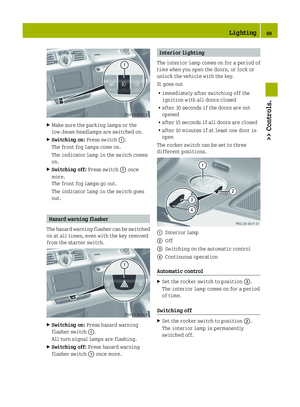 71
71 72
72 73
73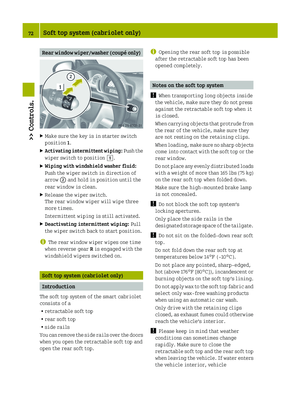 74
74 75
75 76
76 77
77 78
78 79
79 80
80 81
81 82
82 83
83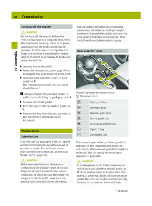 84
84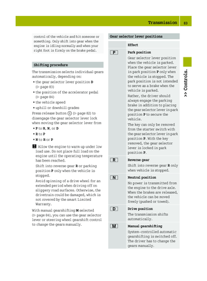 85
85 86
86 87
87 88
88 89
89 90
90 91
91 92
92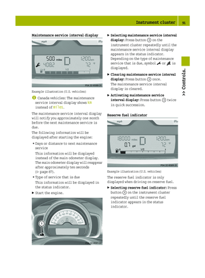 93
93 94
94 95
95 96
96 97
97 98
98 99
99 100
100 101
101 102
102 103
103 104
104 105
105 106
106 107
107 108
108 109
109 110
110 111
111 112
112 113
113 114
114 115
115 116
116 117
117 118
118 119
119 120
120 121
121 122
122 123
123 124
124 125
125 126
126 127
127 128
128 129
129 130
130 131
131 132
132 133
133 134
134 135
135 136
136 137
137 138
138 139
139 140
140 141
141 142
142 143
143 144
144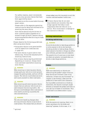 145
145 146
146 147
147 148
148 149
149 150
150 151
151 152
152 153
153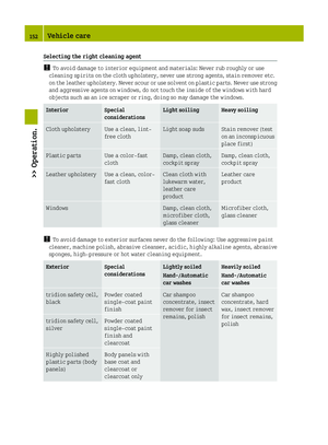 154
154 155
155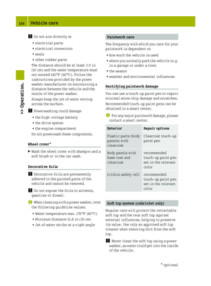 156
156 157
157 158
158 159
159 160
160 161
161 162
162 163
163 164
164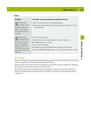 165
165 166
166 167
167 168
168 169
169 170
170 171
171 172
172 173
173 174
174 175
175 176
176 177
177 178
178 179
179 180
180 181
181 182
182 183
183 184
184 185
185 186
186 187
187 188
188 189
189 190
190 191
191 192
192 193
193 194
194 195
195 196
196 197
197 198
198 199
199 200
200 201
201 202
202 203
203 204
204 205
205 206
206 207
207 208
208 209
209 210
210 211
211 212
212 213
213 214
214 215
215 216
216 217
217 218
218 219
219 220
220 221
221 222
222 223
223 224
224 225
225 226
226 227
227