Page 97 of 235
 Owners Manual Using the system
Fig. 108
The air conditioning system: Control elements
Setting temperature
› Turn the control dial A
» Fig. 108 to the right to increase the temperature.
› Turn the control di")
Using the system
Fig. 108
The air conditioning system: Control elements
Setting temperature
› Turn the control dial A
» Fig. 108 to the right to increase the temperature.
› Turn the control dial A
to the left to decrease the temperature.
Controlling blower
› Turn the blower switch B
into one of the positions, 1 to 4, to switch the blower
on.
› Turn the blower switch B
into position 0 to switch the blower off.
› Press the button
4
to close the fresh air supply
» Fig. 108.
Regulating the air distribution
› The direction of the inlet air flow is controlled with air distribution regulator C
» page 94.
Switching the cooling system on and off
› Press the button
AC 1
» Fig. 108 . The indicator light lights up in the button.
› When you again press the button
AC , the air conditioning system is switched
off. The indicator light in the button goes out.
Rear window heater › Press the button
2
. Further information
» page 58.
Auxiliary heating (parking heating)
› Press the button
3
to directly switch on/off the auxiliary heating (auxiliary
heating and ventilation). Further information » page 100. Note
■ The whole heat output will be needed to defrost the windscreen and side win-
dows. No warm air will be fed to the footwell. This can lead to restriction of the
heating comfort. ■ The indicator light AC lights after activation, even if not all of the conditions for
the function of the cooling system have been met » page 94, Introductory infor-
mation . By lighting up of the indicator light in the button, the operational readi-
ness of the cooling system is signalled. Ð 95
The air conditioning system
Page 98 of 235
 Owners Manual Setting the air conditioning system
Recommended basic settings of the control elements of the air conditioning sys-
tem for the respective operating modes:
Set-up Setting of the control dial
Button
Ai")
Setting the air conditioning system
Recommended basic settings of the control elements of the air conditioning sys-
tem for the respective operating modes:
Set-up Setting of the control dial
Button
Air outlet vents 2 A B C 1 4
Defrost/defog windscreen and
side windows
a) Desired tempera-
ture 3 or 4
Automatically
switched on Do not switch on Open and align with the side
window
The fastest heating To the right up to
the stop 3
Switched off Briefly switch on
Opening
Comfortable heating Desired tempera-
ture 2 or 3
Switched off Do not switch on
Opening
The fastest cooling To the left up to
the stop briefly 4, then
2 or 3 Activated Briefly switch on
Opening
Optimal cooling Desired tempera-
ture 1, 2 or 3
Activated Do not switch on Open and align to the roof
Fresh air mode - ventilation To the left up to
the stop Desired position
Switched off Do not switch on
Openinga)
We recommend that you do not use this setting in countries with high humidity levels. This can result in heavy cooling of the window glass and the following fogging from outside. Note
■ Controls A
, B
, C
and the button 1
and 4
» Fig. 108 on page 95
.
■ Air outlet vents 2 » Fig. 106 on page 94 .
■ We recommend that you leave the air outlet vents 3 » Fig. 106 on page 94 in the
opened position. ÐRecirculated air mode
Recirculated air mode prevents polluted air outside the vehicle from getting into
the vehicle, for example when driving through a tunnel or when standing in a
traffic jam.
Switching on
› Press the button
4
» Fig. 108
on page
95 and the indicator light in the but-
ton illuminates. Switching off
› Press the button
again - the indicator light in the button goes out.
Recirculated air mode is switched off automatically if the air distribution control C
» Fig. 108
on page
95 is turned to position . Recirculated air mode can be
switched on again from this setting by repeatedly pressing the button .
WARNING
Do not leave recirculated air mode on over a longer period of time, as “stale”
air can cause fatigue of the driver and passengers, reduce attention levels and
also cause the windows to mist up. The risk of having an accident increases.
Switch off recirculated air mode as soon as the windows start to mist up. Ð
96 Using the system
Page 99 of 235
 Owners Manual Climatronic (automatic air conditioning system)
Introductory information
The Climatronic maintains fully automatically a convenience temperature. This is
achieved by automatically varying the temperat")
Climatronic (automatic air conditioning system)
Introductory information
The Climatronic maintains fully automatically a convenience temperature. This is
achieved by automatically varying the temperature of the air flow, the blower
stages and air distribution. The system also takes sunlight into account, which
eliminates the need to alter the settings manually. The automatic
mode » page 98 ensures maximum well-being of the occupants at all times of
the year.
Description of Climatronic system
The cooling system only operates if the following conditions are met:
› engine running;
› outside temperature above approx. +2 °C;
› AC 13
» Fig. 109 on page 97 switched on.
The AC compressor is switched off at a high coolant temperature in order to pro-
vide cooling at a high load of the engine.
Recommended setting for all periods of the year.
› Set the desired temperature, we recommend 22 °C.
› Press the button
AUTO 8
» Fig. 109
on page 97.
› Move the air outlet vents
2 and 3 so that the air flow is directed slightly up-
wards.
Aeration of the vehicle when ignition is switched off
On models fitted with power sliding/tilting roof with sollar cells, the fresh air
blower is automatically switched over to
“solar mode” if the sun ray's are suffi-
cient after switching off the ignition. The solar cells on the sliding/tilting roof de-
liver power for the fresh air blower. This supplies the interior of the car with fresh
air.
For an optimum ventilation, the air outlet vents 2 and 3 must be opened » Fig. 106
on page 94.
The ventilation functions only when the sliding/tilting roof is closed. Note
■ We recommend that you have the Climatronic system cleaned by a
ŠKODA spe-
cialist garage once every year. ■ On vehicles equipped with a factory-fitted radio or radio navigation system, the
Climatronic information is also shown on their displays. This function can be
switched off, see operating instructions for the radio or navigation system. Ð Overview of the control elements
Fig. 109
Climatronic: Control elements
The buttons Defrost windscreen intensively Air flow to the windows
Air flow to head
Air flow in the footwell
Recirculated air mode
with air quality sensor
Rear window heater The buttons/control dial
Setting of the temperature for the left side, operation of the seat heating of
the left front seat
Automatic mode AUTO Switching off Climatronic
OFF £1
2
3
4
5
6
7
8
9
97
The air conditioning system
Page 100 of 235
 Owners Manual Setting the blower speed
Depending upon vehicle equipment: Button for direct switching on/off of
auxiliary heating » Fig. 110 on page 101, or switching on/off of windscreen
heater »")
Setting the blower speed
Depending upon vehicle equipment: Button for direct switching on/off of
auxiliary heating » Fig. 110 on page 101, or switching on/off of windscreen
heater » Fig. 43 on page 58.
Switching on/off of the temperature setting in dual mode DUALSwitching the cooling system on and off
ACSetting of the temperature for the right side, operation of the seat heating of
the right front seat Note
Below the top row of buttons is located the interior temperature sensor. Do not
stick anything on or cover the sensor, otherwise it could have an unfavourable ef-
fect on the Climatronic. ÐAutomatic mode
The automatic mode is used in order to maintain a constant temperature and to
demist the windows in the interior of the car.
Switching on
› Set a temperature between +18 °C and +26
℃.
› Move the air outlet vents
2 and 3 » Fig. 106 on page 94 so that the air flow is
directed slightly upwards.
› Press the button
AUTO 8
» Fig. 109
on page
97. The indicator light in the top
right or left corner lights up, depending on which mode was last selected.
If the indicator light in the top right corner of the button AUTO lights up, the Cli-
matronic operates in
“HIGH” mode. The “HIGH” mode is the standard setting of
the Climatronic.
When pressing again the button AUTO , the Climatronic changes into the “LOW”
mode and the indicator light in the top left corner lights up. The Climatronic uses
only in this mode the lower blower speed. However taking into account the noise
level, this is more comfortable, yet be aware that the effectiveness of the air con-
ditioning system is reduced particularly if the vehicle is fully occupied.
By pressing the button AUTO again, it is changed to “HIGH” mode.
Automatic mode is switched off by pressing one of the buttons for the air distri-
bution or by increasing/decreasing the blower speed. The temperature is never-
theless regulated. Ð10
11
12
13
14 Switching the cooling system on and off
Switching the cooling system on and off › Press the button
AC » Fig. 109
on page
97. The indicator light in the button
lights up.
› When you again press the button
AC , the air conditioning system is switched
off. The indicator light in the button goes out. Only the function of the ventila-
tion remains active when no lower temperature than the outside temperature
can be reached. Ð Setting temperature
The interior temperature for the left and right side can be set separately.
› The temperature for both sides can be set with the control dial 7
» Fig. 109 on
page 97 after switching on the ignition.
› If you wish to set the temperature for the right side, turn the control dial 14
.
The indicator light in the button DUAL lights up, this indicates that differing
temperatures for the left and right side can be set.
If the indicator light in the button DUAL 12
» Fig. 109
on page 97 is illuminated,
the temperature for both sides cannot be set with the control dial 7
. You can re-
activate this function by pressing the button DUAL . The indicator light in the but-
ton goes out.
The interior temperature can be set between +18 °C and +26 ℃. The interior tem-
perature is regulated automatically within this range. If a temperature lower than
+18 °C is selected, a blue symbol lights up at the start of the numerical scale. If a
temperature higher than +26 °C is selected, a red symbol lights up at the start of
the numerical scale. In both limit positions the Climatronic operates at maximum
cooling or heating capacity, respectively. The temperature is not controlled in this
case.
Lengthy and uneven distribution of the air flow out of the vents (especially
around the feet) and large differences in temperature, for example, when getting
out of the vehicle, can cause susceptible individuals to catch a cold. Ð Recirculated air mode
Recirculated air mode largely prevents polluted air from outside the vehicle get-
ting into the vehicle, for example, when driving through a tunnel or when stand-
ing in a traffic jam. If a considerable increase in concentration of pollutants is rec-
ognized by the air quality sensor, when the automatic air distribution control is £
98 Using the system
Page 101 of 235
 Owners Manual switched on, the air distribution control will temporarily be switched off. If the
concentration of pollutants decreases to the normal level, the air distribution con-
trol is automatically switched o")
switched on, the air distribution control will temporarily be switched off. If the
concentration of pollutants decreases to the normal level, the air distribution con-
trol is automatically switched off so that fresh air can be guided into the vehicle
interior. In recirculated air mode air is sucked out of the interior of the vehicle and
then fed back into the interior. When the automatic air distribution control is
switched on, an air quality sensor measures the concentration of pollutants in the
drawn in air.
Switching recirculated air mode on
› Repeatedly press the button
5
» Fig. 109
on page 97 until the indicator
light on the left side of the button is illuminated.
Switch on automatic air distribution control
› Repeatedly press the button
until the indicator light on the right side of
the button is illuminated.
Switch off automatic air distribution control temporarily › If the air quality sensor does not automatically switch on the air distribution
control in the event of an unpleasant odour, you can switch it on yourself by
pressing the button . The indicator light lights up in the button on the left
side.
Switching recirculated air mode off › Press the button
AUTO or repeatedly press the button
until the indicator
lights in the button go out. WARNING
Do not leave recirculated air mode on over a longer period of time, as “stale”
air can cause fatigue of the driver and passengers, reduce attention levels and
also cause the windows to mist up. The risk of having an accident increases.
Switch off recirculated air mode as soon as the windows start to mist up. Note
■ If the windscreen mists up, press the button 1
» Fig. 109 on page 97.
Press the button AUTO when the windscreen is demisted.
■ The automatic air distribution control operates only if the outside temperature
is higher than approx. 2 °C. Ð Controlling blower
The Climatronic system controls the blower stages automatically in line with the
interior temperature. However, the blower stages can be manually adapted to
suit your particular needs.
› Repeatedly press the button
10
» Fig. 109
on page 97 on the left side (re-
duce blower speed) or on the right side (increase blower speed).
If the blower is switched off, the Climatronic system is switched off.
The set blower speed is displayed above the button when the respective num-
ber of indicator lights come on. WARNING
■ “Stale air”
may result in fatigue in the driver and occupants, reduce attention
levels and also cause the windows to mist up. The risk of having an accident
increases.
■ Do not switch off the Climatronic system for longer than necessary.
■ Switch on the Climatronic system as soon as the windows mist up. Ð Defrosting windscreen
Switching on › Press the button
1
» Fig. 109
on page 97.
› Press the button
11
» Fig. 109
on page 97.
Switching off
› Once again press the button
or the button
AUTO .
› Once again press the button
.
The temperature control is controlled automatically. More air flows out of the air
outlet vents 1 » page 94. Ð
99
The air conditioning system
Page 102 of 235
 Owners Manual Auxiliary heating (auxiliary heating and ventilation)
ä
Introduction
This chapter contains information on the following subjects:
Direct switching on/off 101
System settings 101
Radio remote control")
Auxiliary heating (auxiliary heating and ventilation)
ä
Introduction
This chapter contains information on the following subjects:
Direct switching on/off 101
System settings 101
Radio remote control 101
Changing the battery of the radio remote control 102
Auxiliary heating (parking heating)
The auxiliary heating (auxiliary heating) functions in connection with the air-con-
ditioning system or Climatronic.
It can be used when stationary, when the engine is switched off to preheat the
vehicle and while driving (e.g. during the heating phase of the engine).
The engine is also preheated, if the auxiliary heating is switched on when the ve-
hicle is stationary and the engine is switched off. This is not valid for vehicles with
the 3.6 l/191 kW
FSI engine.
The auxiliary heating (parking heating) warms up the coolant by combusting fuel
from the vehicle tank. The coolant warms up the air, which (if the blower speed is
not set to zero) flows into the passenger compartment.
Auxiliary ventilation
The auxiliary ventilation enables fresh air to flow into the vehicle interior by
switching off the engine, whereby the interior temperature is effectively de-
creased (e.g. with the vehicle parked in the sun). WARNING
■ The auxiliary heating must never be operated in closed rooms - risk of poi-
soning! ■ The auxiliary heating must not be running during refuelling - risk of fire.
■ The exhaust pipe of the auxiliary heating is located on the underside of the
vehicle. Therefore, if you wish to operate the auxiliary heating, do not park the
vehicle in such a way that the exhaust gases from the auxiliary heating can
come into contact with highly flammable materials (e.g. dry grass) or easily in-
flammable substances (e.g. spilt fuel). Note
■ If the auxiliary heating runs, the fuel consumption comes from the vehicle tank.
The auxiliary heating automatically controls the filling level in the fuel tank. If only
a low quantity of fuel is present in the fuel tank, the function of the auxiliary
heating is blocked. ■ The exhaust pipe of the auxiliary heating, which is located on the underside of
the vehicle, must not be clogged and the exhaust flow must not be blocked.
■ If the auxiliary heating and ventilation is running, the vehicle battery discharges.
If the auxiliary heating and ventilation has been operated several times over a
longer period, the vehicle must be driven a few kilometres in order to recharge
the vehicle battery.
■ The auxiliary heating only switches the blower on, if it has achieved a coolant
temperature of approx. 50 °C.
■ At low outside temperatures, this can result in a formation of water vapour in
the area of the engine compartment. This is quite normal and is not an operating
problem.
■ After switching off the auxiliary heating, the coolant pump runs for a short peri-
od.
■ The auxiliary heating and ventilation does not switch on or comes on, if the ve-
hicle battery indicates a low loading state » page 186, Automatic load deactiva-
tion .
■ The auxiliary heating (parking heating) does not switch on, if the following was
shown in the information display or before switching off the ignition: Please re-
fuel! ■ The air inlet in front of the windscreen must be free of ice, snow or leaves in
order to ensure that the auxiliary heating operates properly.
■ So that warm air can flow into the vehicle interior after switching on the auxili-
ary heating, you must maintain the comfort temperature normally selected by
you, leave the fan switched on and leave the air outlet vents in an open position.
It is recommended to put the air flow in the position or . Ð
100 Using the system
Page 103 of 235
 Owners Manual Direct switching on/off
Fig. 110
Button for direct switching on/
off of the auxiliary heating (aux-
iliary heating and ventilation) on
the operating part of the air con-
ditioning system
First read a")
Direct switching on/off
Fig. 110
Button for direct switching on/
off of the auxiliary heating (aux-
iliary heating and ventilation) on
the operating part of the air con-
ditioning system
First read and observe the introductory information and safety warn-
ings on page 100.
The auxiliary heating (auxiliary heating and ventilation) can be
directly switched
on or off at any time using the button » Fig. 110 on the operating part of the
air-conditioning system, on the operating part of the Climatronic system or via the
radio remote control » page 101.
If the auxiliary heating and ventilation is not switched off earlier, it switches off
automatically after the set operating period, in the menu Running time has ex-
pired. ÐSystem settings
First read and observe the introductory information and safety warn-
ings on page 100.
The following menu items can be selected in the menu
Aux. heating in the infor-
mation display (depending on the equipment fitted in the vehicle):
■ Weekday - Set the current weekday.
■ Time - Set the desired running time in 5
minute increments. The running time
can be 10 to 60 minutes.
■ Mode - Set the desired heating/ventilation mode.
■ Start time 1-3 - In each pre-set time, the day and the time (hour and minute) can
be set for switching on the auxiliary heating and/or ventilation. An empty posi-
tion can be found between Sunday and Monday when selecting the day. If this
empty position is selected, the activation is performed without taking into ac-
count the day.
■ Activate - Enable pre-set mode.
ä
ä ■
Dectivate - Disable pre-set mode.
■ Factory setting - Restore factory setting.
■ Back - Return to main menu.
Only one programmed pre-set time can be active.
The last programmed pre-set time remains active.
After the auxiliary heating activates at the set time, it is necessary to pre-set a
time again.
If the pre-set menu is closed by selecting the menu item Back or if no changes
are made on the display for more than 10
seconds, the set values are stored, but
the pre-set time is not activated.
An indicator light on the button » Fig. 110 on page 101 is illuminated when the
system is running.
The running system deactivates after expiration of the operating period or can be
deactivated earlier by pressing the button to directly switch on/off the auxiliary
heating or by using the radio remote control.
Ð Radio remote control
Fig. 111
Auxiliary heating: Radio remote control
First read and observe the introductory information and safety warn-
ings on page 100.
›
For switching on, press the button
ON » Fig. 111.
› For switching off, press the button
OFF .
The transmitter and the battery are housed in the housing of the remote control.
The receiver is located in the interior of the vehicle. £
ä
101
The air conditioning system
Page 104 of 235
 Owners Manual If the battery is properly charged, the effective range is up to 600
m. To switch
on/off the auxiliary heating, hold the radio remote control vertically with the an-
tenna A
» Fig. 111 facing up")
If the battery is properly charged, the effective range is up to 600
m. To switch
on/off the auxiliary heating, hold the radio remote control vertically with the an-
tenna A
» Fig. 111 facing upwards. The antenna must not be covered with the fin-
gers or the palm of the hand during this process. Obstacles between the radio re-
mote control and the vehicle, bad weather conditions and a weaker battery can
clearly reduce the range.
The auxiliary heating can only be switched on/off safely using the radio remote
control, if the distance between the radio remote control and the vehicle is at
least 2 m.
Warning light in the radio remote control
The indicator light in the radio remote control C
» Fig. 111 indicates after a key-
stroke if the remote control signal was received by the auxiliary heating and if the
battery is adequately charged.
Display indicator light Importance
Lights up green for 2 seconds. The auxiliary heating was switched on.
Lights up red for 2 seconds. The auxiliary heating was switched off.
Slowly flashes green for 2 seconds. The ignition signal was not received.
Quickly flashes green for 2 seconds. The auxiliary heating is blocked, e. g
because the tank is nearly empty or
there is a fault in the auxiliary heating.
Flashes red for 2 seconds. The switch off signal was not received.
Lights up orange for 2 seconds, then
green or red. The battery is weak, however the
switching on or off signal was received.
Lights up orange for 2 seconds, then
flashes green or red. The battery is weak, however the
switching on or off signal was not re-
ceived.
Flashes orange for 5 seconds. The battery is discharged, however the
switching on or off signal was not re-
ceived.CAUTION
The radio remote control comprises electronic components and must therefore be
protected against water, severe impacts and direct sunlight. Ð Changing the battery of the radio remote control
First read and observe the introductory information and safety warn-
ings on page 100.
If the indicator light on the radio remote control indicates a weak or discharged
battery,
C
» Fig. 111 on page 101, it must be replaced. The battery is located under
a cover B
» Fig. 111 on page 101 on the back of the radio remote control.
› Insert a flat, blunt object, such as a coin, into the gap on the battery cover, turn
the cover in the opposite direction of the arrow up to the mark and unlock it.
› Change the battery, replace the battery cover and lock it by moving it in the di-
rection of the arrow. For the sake of the environment
Dispose of the old battery in accordance with environmental regulations. Note
■ Pay attention to the correct polarity when changing the battery.
■ The replacement battery must have the same specification as the original bat-
tery. Ð ä
102 Using the system
 1
1 2
2 3
3 4
4 5
5 6
6 7
7 8
8 9
9 10
10 11
11 12
12 13
13 14
14 15
15 16
16 17
17 18
18 19
19 20
20 21
21 22
22 23
23 24
24 25
25 26
26 27
27 28
28 29
29 30
30 31
31 32
32 33
33 34
34 35
35 36
36 37
37 38
38 39
39 40
40 41
41 42
42 43
43 44
44 45
45 46
46 47
47 48
48 49
49 50
50 51
51 52
52 53
53 54
54 55
55 56
56 57
57 58
58 59
59 60
60 61
61 62
62 63
63 64
64 65
65 66
66 67
67 68
68 69
69 70
70 71
71 72
72 73
73 74
74 75
75 76
76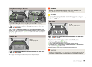 77
77 78
78 79
79 80
80 81
81 82
82 83
83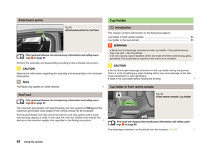 84
84 85
85 86
86 87
87 88
88 89
89 90
90 91
91 92
92 93
93 94
94 95
95 96
96 97
97 98
98 99
99 100
100 101
101 102
102 103
103 104
104 105
105 106
106 107
107 108
108 109
109 110
110 111
111 112
112 113
113 114
114 115
115 116
116 117
117 118
118 119
119 120
120 121
121 122
122 123
123 124
124 125
125 126
126 127
127 128
128 129
129 130
130 131
131 132
132 133
133 134
134 135
135 136
136 137
137 138
138 139
139 140
140 141
141 142
142 143
143 144
144 145
145 146
146 147
147 148
148 149
149 150
150 151
151 152
152 153
153 154
154 155
155 156
156 157
157 158
158 159
159 160
160 161
161 162
162 163
163 164
164 165
165 166
166 167
167 168
168 169
169 170
170 171
171 172
172 173
173 174
174 175
175 176
176 177
177 178
178 179
179 180
180 181
181 182
182 183
183 184
184 185
185 186
186 187
187 188
188 189
189 190
190 191
191 192
192 193
193 194
194 195
195 196
196 197
197 198
198 199
199 200
200 201
201 202
202 203
203 204
204 205
205 206
206 207
207 208
208 209
209 210
210 211
211 212
212 213
213 214
214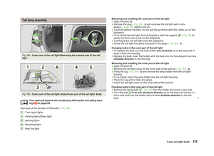 215
215 216
216 217
217 218
218 219
219 220
220 221
221 222
222 223
223 224
224 225
225 226
226 227
227 228
228 229
229 230
230 231
231 232
232 233
233 234
234