2012 MERCEDES-BENZ SL ROADSTER open bonnet
[x] Cancel search: open bonnetPage 10 of 637
Bonnet
Active bonnet (pedestrian protec-tion) ............................................... 562
Closing ........................................... 563
Display message ............................ 270
Important safety notes .................. 562
Opening ......................................... 563
Boot
Emergency release .......................... 99
Important safety notes .................... 94
Locking separately ........................... 98
Opening/closing (automatically
from inside) ...................................... 98
Opening/closing (automatically
from outside) ................................... 95
Opening/closing (from the out-
side, HANDS-FREE ACCESS) ............ 96
Opening/closing (manually from
outside) ............................................ 95
Overview .......................................... 94
Power closing .................................. 93
Boot lid
Display message ............................ 270
Opening dimensions ...................... 629
Opening/closing .............................. 94
Boot load (maximum) ........................ 629
Boot separator
Display message ............................ 271
Fitting ............................................ 106
General notes ................................ 105
Opening/closing ............................ 106
Removing ....................................... 106
Bottle holders .................................... 549
Brake Assist
see BAS (Brake Assist System)
Brake fluid
Display message ............................ 253
Notes ............................................. 627
Brake lamps
Adaptive ........................................... 73
Display message ............................ 256
Brakes
ABS .................................................. 71
BAS .................................................. 71
BAS PLUS ........................................ 72
Brake fluid (notes) ......................... 627
Display message ............................ 248
Driving tips .................................... 179 High-performance brake system .... 180
Important safety notes .................. 179
Parking brake ................................ 176
Warning lamp ................................. 275
Breakdown
see Flat tyre
see Towing away
Buttons on the COMAND control-
ler ........................................................ 296 C
Call ...................................................... 397
Accepting/ending/rejecting .......... 396
Connecting .................................... 397
see Telephone
Call list
Display details ............................... 406
Call lists
Deleting ......................................... 407
Opening and selecting an entry ..... 405
Saving an entry in the address
book .............................................. 406
Calling up a fault
see Display messages
Capacities (technical data) ............... 622
Car
see Vehicle
Car key
see Key
Car wash (care) ................................. 568
Care
Automatic car wash ....................... 568
Carpets .......................................... 574
Display ........................................... 572
Exhaust pipe .................................. 572
Exterior lighting ............................. 571
Gear or selector lever .................... 573
High-pressure cleaner .................... 569
Interior ........................................... 572
Matt paintwork .............................. 570
Night View Assist Plus ................... 572
Notes ............................................. 568
Paint .............................................. 570
Plastic trim .................................... 573
Reversing camera .......................... 572
Roof lining ...................................... 574
Seat belt ........................................ 574 Index
7
Page 41 of 637
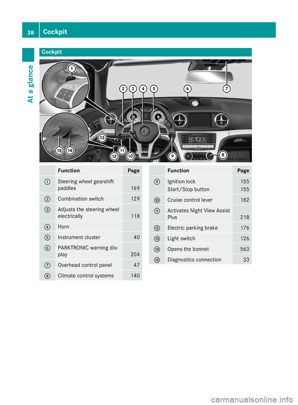
Cockpit
Function Page
:
Steering wheel gearshift
paddles
169
;
Combination switch 129
=
Adjusts the steering wheel
electrically
118
?
Horn
A
Instrument cluster 40
B
PARKTRONIC warning dis-
play
204
C
Overhead control panel 47
D
Climate control systems 140 Function Page
E
Ignition lock 155
Start/Stop button 155
F
Cruise control lever 182
G
Activates Night View Assist
Plus 218
H
Electric parking brake 176
I
Light switch 126
J
Opens the bonnet 563
K
Diagnostics connection 3338
CockpitAt a glance
Page 42 of 637
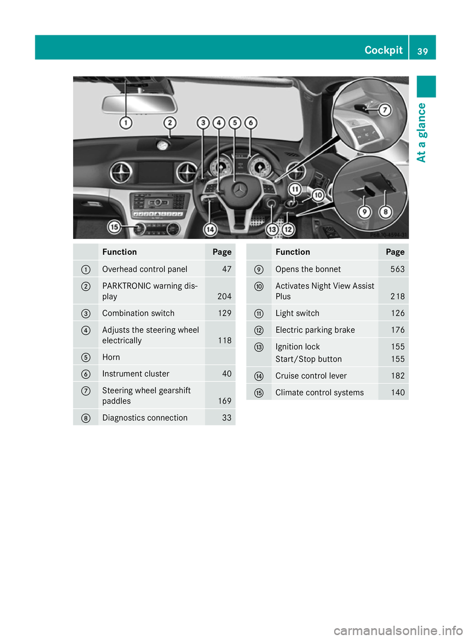
Function Page
:
Overhead control panel 47
;
PARKTRONIC warning dis-
play 204
=
Combination switch 129
?
Adjusts the steering wheel
electrically
118
A
Horn
B
Instrument cluster 40
C
Steering wheel gearshift
paddles
169
D
Diagnostics connection 33 Function Page
E
Opens the bonnet 563
F
Activates Night View Assist
Plus 218
G
Light switch 126
H
Electric parking brake 176
I
Ignition lock 155
Start/Stop button 155
J
Cruise control lever 182
K
Climate control systems 140Cockpit
39At a glance
Page 82 of 637
This steering support is provided in particular
if:
R both right wheels or both left wheels are on
a wet or slippery road surface when you
brake.
R the vehicle starts to skid.
Important safety notes i
Observe the "Important safety notes" sec-
tion (Y page 70).
No steering support is provided from STEER
CONTROL, if:
R ESP ®
is malfunctioning.
R the steering is faulty.
Power steering will, however, continue to
function. Anti-theft systems
Immobiliser
X To activate with the key: remove the key
from the ignition lock.
X To activate with KEYLESS-GO: switch the
ignition off and open the driver's door.
X To deactivate: switch on the ignition.
The immobiliser prevents your vehicle from
being started without the correct key.
When leaving the vehicle, always take the
SmartKey with you and lock the vehicle. The
engine can be started by anyone with a valid
key that is left inside the vehicle.
i The immobiliser is always deactivated
when you start the engine. ATA (Anti-Theft Alarm system)
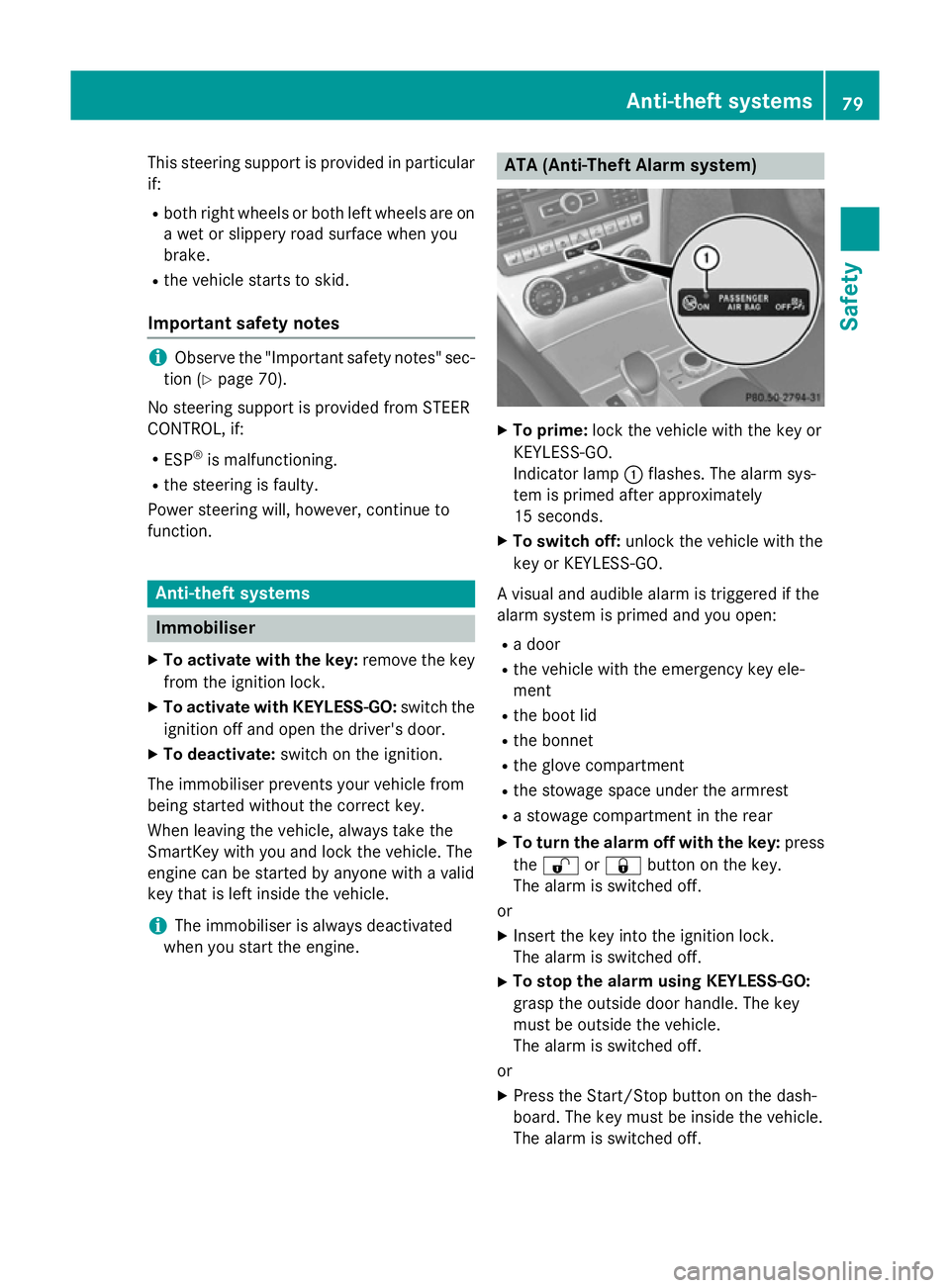
X
To prime: lock the vehicle with the key or
KEYLESS-GO.
Indicator lamp :flashes. The alarm sys-
tem is primed after approximately
15 seconds.
X To switch off: unlock the vehicle with the
key or KEYLESS-GO.
A visual and audible alarm is triggered if the
alarm system is primed and you open:
R a door
R the vehicle with the emergency key ele-
ment
R the boot lid
R the bonnet
R the glove compartment
R the stowage space under the armrest
R a stowage compartment in the rear
X To turn the alarm off with the key: press
the % or& button on the key.
The alarm is switched off.
or
X Insert the key into the ignition lock.
The alarm is switched off.
X To stop the alarm using KEYLESS-GO:
grasp the outside door handle. The key
must be outside the vehicle.
The alarm is switched off.
or
X Press the Start/Stop button on the dash-
board. The key must be inside the vehicle.
The alarm is switched off. Anti-theft systems
79Safety Z
Page 139 of 637
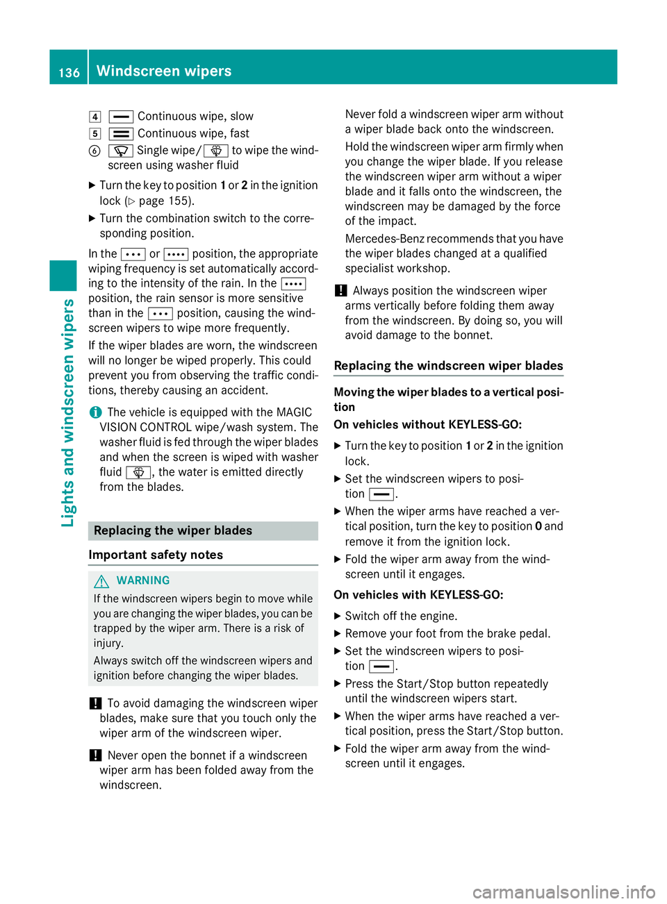
4
° Continuous wipe, slow
5 ¯ Continuous wipe, fast
B í Single wipe/ îto wipe the wind-
screen using washer fluid
X Turn the key to position 1or 2in the ignition
lock (Y page 155).
X Turn the combination switch to the corre-
sponding position.
In the ÄorÅ position, the appropriate
wiping frequency is set automatically accord- ing to the intensity of the rain. In the Å
position, the rain sensor is more sensitive
than in the Äposition, causing the wind-
screen wipers to wipe more frequently.
If the wiper blades are worn, the windscreen
will no longer be wiped properly. This could
prevent you from observing the traffic condi-
tions, thereby causing an accident.
i The vehicle is equipped with the MAGIC
VISION CONTROL wipe/wash system. The
washer fluid is fed through the wiper blades
and when the screen is wiped with washer
fluid î, the water is emitted directly
from the blades. Replacing the wiper blades
Important safety notes G
WARNING
If the windscreen wipers begin to move while
you are changing the wiper blades, you can be trapped by the wiper arm. There is a risk of
injury.
Always switch off the windscreen wipers and
ignition before changing the wiper blades.
! To avoid damaging the windscreen wiper
blades, make sure that you touch only the
wiper arm of the windscreen wiper.
! Never open the bonnet if a windscreen
wiper arm has been folded away from the
windscreen. Never fold a windscreen wiper arm without
a wiper blade back onto the windscreen.
Hold the windscreen wiper arm firmly when you change the wiper blade. If you release
the windscreen wiper arm without a wiper
blade and it falls onto the windscreen, the
windscreen may be damaged by the force
of the impact.
Mercedes-Benz recommends that you have the wiper blades changed at a qualified
specialist workshop.
! Always position the windscreen wiper
arms vertically before folding them away
from the windscreen. By doing so, you will
avoid damage to the bonnet.
Replacing the windscreen wiper blades Moving the wiper blades to a vertical posi-
tion
On vehicles without KEYLESS-GO:
X Turn the key to position 1or 2in the ignition
lock.
X Set the windscreen wipers to posi-
tion °.
X When the wiper arms have reached a ver-
tical position, turn the key to position 0and
remove it from the ignition lock.
X Fold the wiper arm away from the wind-
screen until it engages.
On vehicles with KEYLESS-GO: X Switch off the engine.
X Remove your foot from the brake pedal.
X Set the windscreen wipers to posi-
tion °.
X Press the Start/Stop button repeatedly
until the windscreen wipers start.
X When the wiper arms have reached a ver-
tical position, press the Start/Stop button.
X Fold the wiper arm away from the wind-
screen until it engages. 136
Windscreen wipersLights and windscreen wipers
Page 153 of 637
Residual heat is deactivated automatically:
R after approximately 30 minutes
R when the ignition is switched on
R if the battery voltage drops Adjusting the air vents
Important safety notes
G
WARNING
Very hot or very cold air can flow from the air vents. This could result in burns or frostbite in the immediate vicinity of the air vents. There
is a risk of injury.
Make sure that all vehicle occupants always
maintain a sufficient distance to the air out-
lets. If necessary, redirect the airflow to
another area of the vehicle interior. G
WARNING
When AIRSCARF is switched on, very hot air
can flow from the vents in the head restraints. This could result in burns in the immediate
vicinity of the air vents. There is a risk of injury.
Reduce the heater output before it becomes
too hot.
In order to ensure the direct flow of fresh air
through the air vents into the vehicle interior, please observe the following notes:
R keep the air inlet grille on the bonnet and in
the engine compartment on the front-
passenger side free of blockages, such as
ice, snow or leaves.
R never cover the vents or ventilation grilles
in the vehicle interior.
i You can move the adjusters for the air
vents vertically or horizontally to set the
direction of the airflow.
i Optimal climate control function is ach-
ieved by opening the air vents fully and set-
ting the adjusters to the middle position. Setting the centre air vents
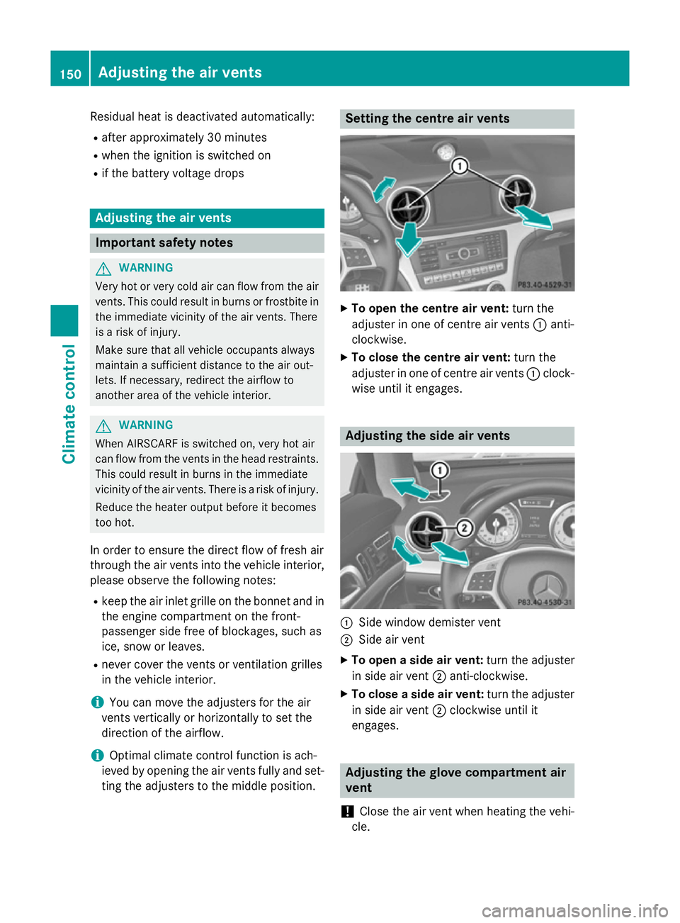
X
To open the centre air vent: turn the
adjuster in one of centre air vents :anti-
clockwise.
X To close the centre air vent: turn the
adjuster in one of centre air vents :clock-
wise until it engages. Adjusting the side air vents
:
Side window demister vent
; Side air vent
X To open a side air vent: turn the adjuster
in side air vent ;anti-clockwise.
X To close a side air vent: turn the adjuster
in side air vent ;clockwise until it
engages. Adjusting the glove compartment air
vent
! Close the air vent when heating the vehi-
cle. 150
Adjusting the air ventsClimate cont
rol
Page 231 of 637
Useful information
i This Owner's Manual describes all mod-
els, series and optional equipment for your
vehicle that were available at the time of
going to press. National variations are pos- sible. Note that your vehicle may not be
equipped with all of the functions descri-
bed. This is also the case for systems and
functions relevant to safety.
i Read the information on qualified special-
ist workshops: (Y page 34). Important safety notes
G
WARNING
Operating the integrated information systems and communications equipment in the vehicle
while driving will distract you from traffic con-
ditions. You could then lose control of the
vehicle. There is a risk of an accident.
Only operate these devices if road traffic con-
ditions permit. If you are unsure about the
surrounding conditions, pull over to a safe
location and make entries only while the vehi-
cle is stationary. G
WARNING
If the instrument cluster has failed or mal-
functioned, you may not recognise function
restrictions relevant to safety. The operating
safety of your vehicle may be impaired. There is a risk of an accident.
Drive on carefully. Have the vehicle checked
at a qualified specialist workshop immedi-
ately.
You must observe the legal requirements for
the country in which you are currently driving when operating the on-board computer.
The on-board computer only shows messages
or warnings from certain systems in the mul- tifunction display. You should therefore make
sure your vehicle is operating safely at all times. Otherwise, a vehicle that is not oper-
ating safely may cause an accident.
For an overview, see the instrument panel
illustration (Y
page 40). Displays and operation
Instrument cluster lighting
The lighting in the instrument cluster, in the
displays and the controls in the vehicle inte-
rior can be adjusted using the brightness con- trol knob.
The brightness control knob is on the bottom
left of the instrument cluster (Y page 40).
X Turn the brightness control knob anti-
clockwise or clockwise.
If the light switch is set to Ã,Tor
L, the brightness is dependant upon
the brightness of the ambient light.
i The light sensor in the instrument cluster
automatically controls the brightness of
the multifunction display.
In daylight, the displays in the instrument
cluster are not lit. Coolant temperature gauge
G
WARNING
If you open the bonnet while the engine is
overheating or while there is a fire in the
engine compartment, you could come into
contact with hot gases or other leaking ser-
vice products. There is a danger of injury.
Allow an overheating engine to cool down
before opening the bonnet. If there is a fire in the engine compartment, leave the bonnet
closed and notify the fire brigade.
The coolant temperature gauge is in the
instrument cluster on the right-hand side
(Y page 40).
Under normal operating conditions and with
the specified coolant level, the coolant tem-
perature may rise to 120 †. 228
Displays and operationOn-board computer and displays
Page 261 of 637
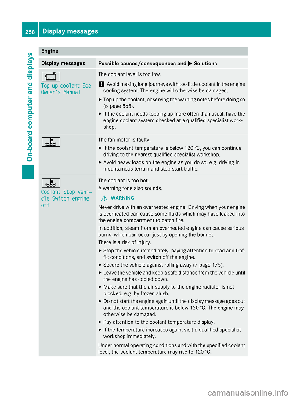
Engine
Display messages
Possible causes/consequences and
M
MSolutions +
Top Top
up
upcoolant
coolant See
See
Owner's Manual
Owner's Manual The coolant level is too low.
! Avoid making long journeys with too little coolant in the engine
cooling system. The engine will otherwise be damaged.
X Top up the coolant, observing the warning notes before doing so
(Y page 565).
X If the coolant needs topping up more often than usual, have the
engine coolant system checked at a qualified specialist work-
shop. ? The fan motor is faulty.
X If the coolant temperature is below 120 †, you can continue
driving to the nearest qualified specialist workshop.
X Avoid heavy loads on the engine as you do so, e.g. driving in
mountainous terrain and stop-start traffic. ?
Coolant Stop vehi‐ Coolant Stop vehi‐
cle Switch engine cle Switch engine
off off The coolant is too hot.
A warning tone also sounds.
G WARNING
Never drive with an overheated engine. Driving when your engine is overheated can cause some fluids which may have leaked into
the engine compartment to catch fire.
In addition, steam from an overheated engine can cause serious
burns, which can occur just by opening the bonnet.
There is a risk of injury.
X Stop the vehicle immediately, paying attention to road and traf-
fic conditions, and switch off the engine.
X Secure the vehicle against rolling away (Y page 175).
X Leave the vehicle and keep a safe distance from the vehicle until
the engine has cooled down.
X Make sure that the air supply to the engine radiator is not
blocked, e.g. by frozen slush.
X Do not start the engine again until the display message goes out
and the coolant temperature is below 120 †. The engine may
otherwise be damaged.
X Pay attention to the coolant temperature display.
X If the temperature increases again, visit a qualified specialist
workshop immediately.
Under normal operating conditions and with the specified coolant
level, the coolant temperature may rise to 120 †. 258
Display messagesOn-board computer and displays