2012 MERCEDES-BENZ SL ROADSTER bonnet
[x] Cancel search: bonnetPage 10 of 637
Bonnet
Active bonnet (pedestrian protec-tion) ............................................... 562
Closing ........................................... 563
Display message ............................ 270
Important safety notes .................. 562
Opening ......................................... 563
Boot
Emergency release .......................... 99
Important safety notes .................... 94
Locking separately ........................... 98
Opening/closing (automatically
from inside) ...................................... 98
Opening/closing (automatically
from outside) ................................... 95
Opening/closing (from the out-
side, HANDS-FREE ACCESS) ............ 96
Opening/closing (manually from
outside) ............................................ 95
Overview .......................................... 94
Power closing .................................. 93
Boot lid
Display message ............................ 270
Opening dimensions ...................... 629
Opening/closing .............................. 94
Boot load (maximum) ........................ 629
Boot separator
Display message ............................ 271
Fitting ............................................ 106
General notes ................................ 105
Opening/closing ............................ 106
Removing ....................................... 106
Bottle holders .................................... 549
Brake Assist
see BAS (Brake Assist System)
Brake fluid
Display message ............................ 253
Notes ............................................. 627
Brake lamps
Adaptive ........................................... 73
Display message ............................ 256
Brakes
ABS .................................................. 71
BAS .................................................. 71
BAS PLUS ........................................ 72
Brake fluid (notes) ......................... 627
Display message ............................ 248
Driving tips .................................... 179 High-performance brake system .... 180
Important safety notes .................. 179
Parking brake ................................ 176
Warning lamp ................................. 275
Breakdown
see Flat tyre
see Towing away
Buttons on the COMAND control-
ler ........................................................ 296 C
Call ...................................................... 397
Accepting/ending/rejecting .......... 396
Connecting .................................... 397
see Telephone
Call list
Display details ............................... 406
Call lists
Deleting ......................................... 407
Opening and selecting an entry ..... 405
Saving an entry in the address
book .............................................. 406
Calling up a fault
see Display messages
Capacities (technical data) ............... 622
Car
see Vehicle
Car key
see Key
Car wash (care) ................................. 568
Care
Automatic car wash ....................... 568
Carpets .......................................... 574
Display ........................................... 572
Exhaust pipe .................................. 572
Exterior lighting ............................. 571
Gear or selector lever .................... 573
High-pressure cleaner .................... 569
Interior ........................................... 572
Matt paintwork .............................. 570
Night View Assist Plus ................... 572
Notes ............................................. 568
Paint .............................................. 570
Plastic trim .................................... 573
Reversing camera .......................... 572
Roof lining ...................................... 574
Seat belt ........................................ 574 Index
7
Page 41 of 637
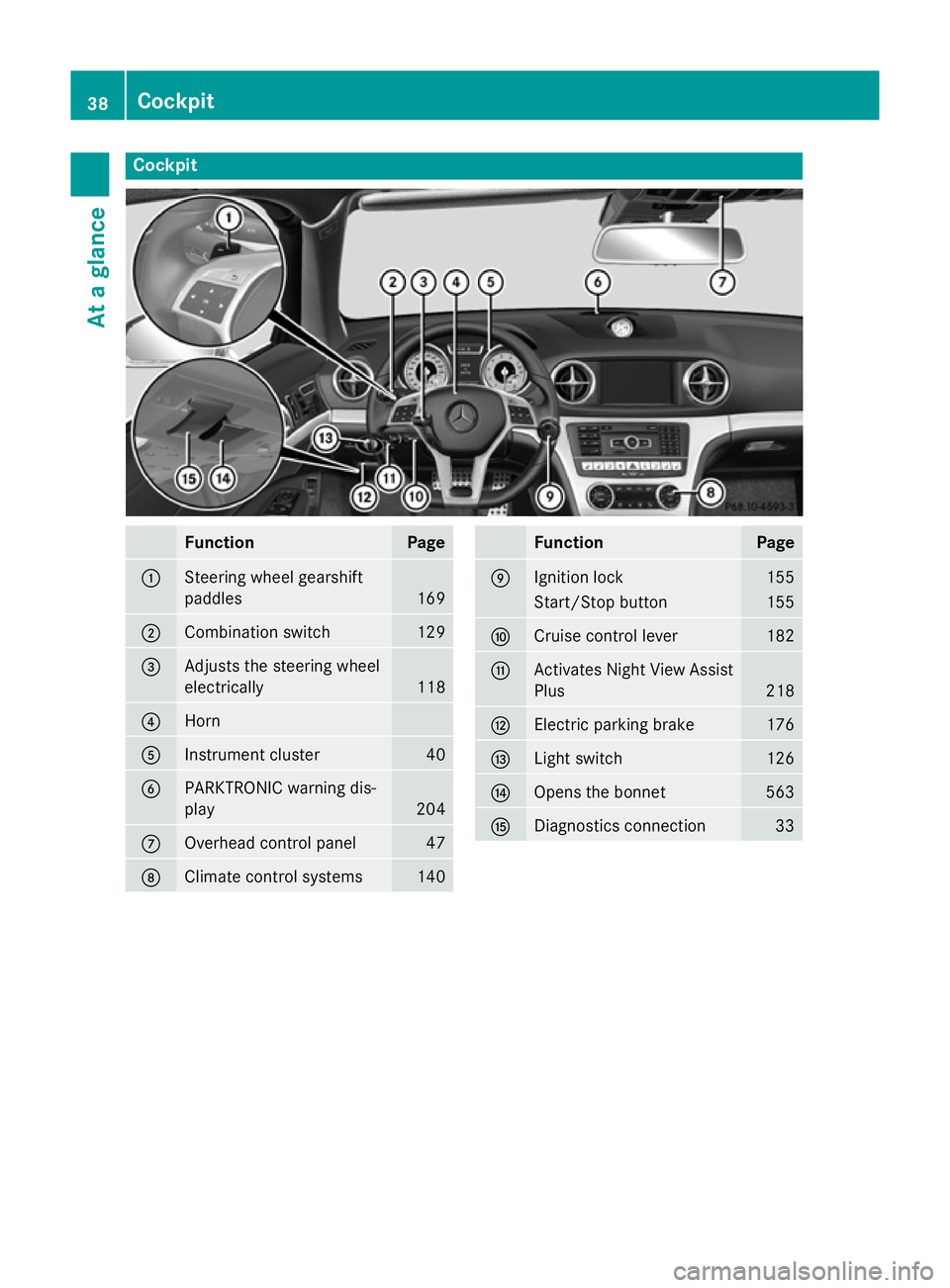
Cockpit
Function Page
:
Steering wheel gearshift
paddles
169
;
Combination switch 129
=
Adjusts the steering wheel
electrically
118
?
Horn
A
Instrument cluster 40
B
PARKTRONIC warning dis-
play
204
C
Overhead control panel 47
D
Climate control systems 140 Function Page
E
Ignition lock 155
Start/Stop button 155
F
Cruise control lever 182
G
Activates Night View Assist
Plus 218
H
Electric parking brake 176
I
Light switch 126
J
Opens the bonnet 563
K
Diagnostics connection 3338
CockpitAt a glance
Page 42 of 637
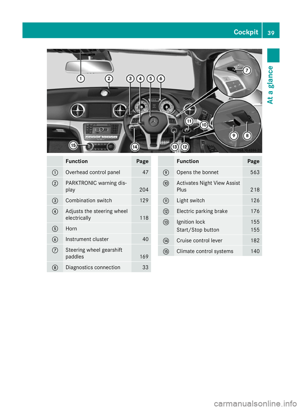
Function Page
:
Overhead control panel 47
;
PARKTRONIC warning dis-
play 204
=
Combination switch 129
?
Adjusts the steering wheel
electrically
118
A
Horn
B
Instrument cluster 40
C
Steering wheel gearshift
paddles
169
D
Diagnostics connection 33 Function Page
E
Opens the bonnet 563
F
Activates Night View Assist
Plus 218
G
Light switch 126
H
Electric parking brake 176
I
Ignition lock 155
Start/Stop button 155
J
Cruise control lever 182
K
Climate control systems 140Cockpit
39At a glance
Page 55 of 637
rate of deceleration or acceleration of the
vehicle. This process is pre-emptive in nature. The triggering process must take place in
good time at the start of the collision.
The rate of vehicle deceleration or accelera-
tion and the direction of the force are essen- tially determined by:
R the distribution of forces during the colli-
sion
R the collision angle
R the deformation characteristics of the vehi-
cle
R the characteristics of the object with which
the vehicle has collided.
Factors which can only be seen and measured after a collision has occurred do not play a
decisive role in the deployment of an airbag,
nor do they provide an indication of airbag
deployment.
The vehicle may be deformed significantly,
e.g. the bonnet or the wing, without an airbag being deployed. This is the case if only parts
which are relatively easily deformed are affec-ted and the rate of deceleration is not high.
Conversely, airbags may be deployed even
though the vehicle suffers only minor defor-
mation. This is the case if, for example, very
rigid vehicle parts such as longitudinal body
members are hit, and sufficient deceleration
occurs as a result.
i The belt tensioners can only be triggered
if the seat belt tongues are correctly
engaged in the seat belt buckles.
i Not all airbags are deployed in an acci-
dent. The different airbag systems work
independently of each other.
How the airbag system works is deter-
mined by the severity of the collision detec- ted, especially the vehicle deceleration or
acceleration, and the apparent type of acci- dent:
R frontal collision
R side impact R
rear impact
R overturn Airbags
Important safety notes G
WARNING
Airbags provide additional protection; they
are not, however, a substitute for seat belts.
Observe the following notes to reduce the risk of serious or even fatal injury caused by airbag
deployment:
R all vehicle occupants – in particular, preg-
nant women – must wear their seat belt
correctly at all times and lean back against
the backrest, which should be positioned
as close to the vertical as possible. The
head restraint must support the back of the
head at about eye level.
R always secure children less than 1.50 m tall
or under 12 years of age in suitable child
restraint systems.
R all vehicle occupants must select a seat
position that is as far away from the airbag
as possible. The driver's seat position must allow the vehicle to be driven safely. The
driver's chest should be as far away from
the centre of the driver's airbag cover as
possible.
R move the front-passenger seat as far back
as possible. This is especially important if
you have secured a child in a child restraint
system on the front-passenger seat.
R vehicle occupants – in particular, children –
must not lean their heads into the area of
the window in which the sidebag/headbag
is deployed.
R rearward-facing child restraint systems
must not be fitted to the front-passenger
seat unless the front-passenger front air-
bag has been disabled. The front-passenger
front airbag is disabled if a child restraint
system with transponders for automatic
child seat recognition is fitted to the front- 52
Occupant safetySafety
Page 82 of 637
This steering support is provided in particular
if:
R both right wheels or both left wheels are on
a wet or slippery road surface when you
brake.
R the vehicle starts to skid.
Important safety notes i
Observe the "Important safety notes" sec-
tion (Y page 70).
No steering support is provided from STEER
CONTROL, if:
R ESP ®
is malfunctioning.
R the steering is faulty.
Power steering will, however, continue to
function. Anti-theft systems
Immobiliser
X To activate with the key: remove the key
from the ignition lock.
X To activate with KEYLESS-GO: switch the
ignition off and open the driver's door.
X To deactivate: switch on the ignition.
The immobiliser prevents your vehicle from
being started without the correct key.
When leaving the vehicle, always take the
SmartKey with you and lock the vehicle. The
engine can be started by anyone with a valid
key that is left inside the vehicle.
i The immobiliser is always deactivated
when you start the engine. ATA (Anti-Theft Alarm system)
X
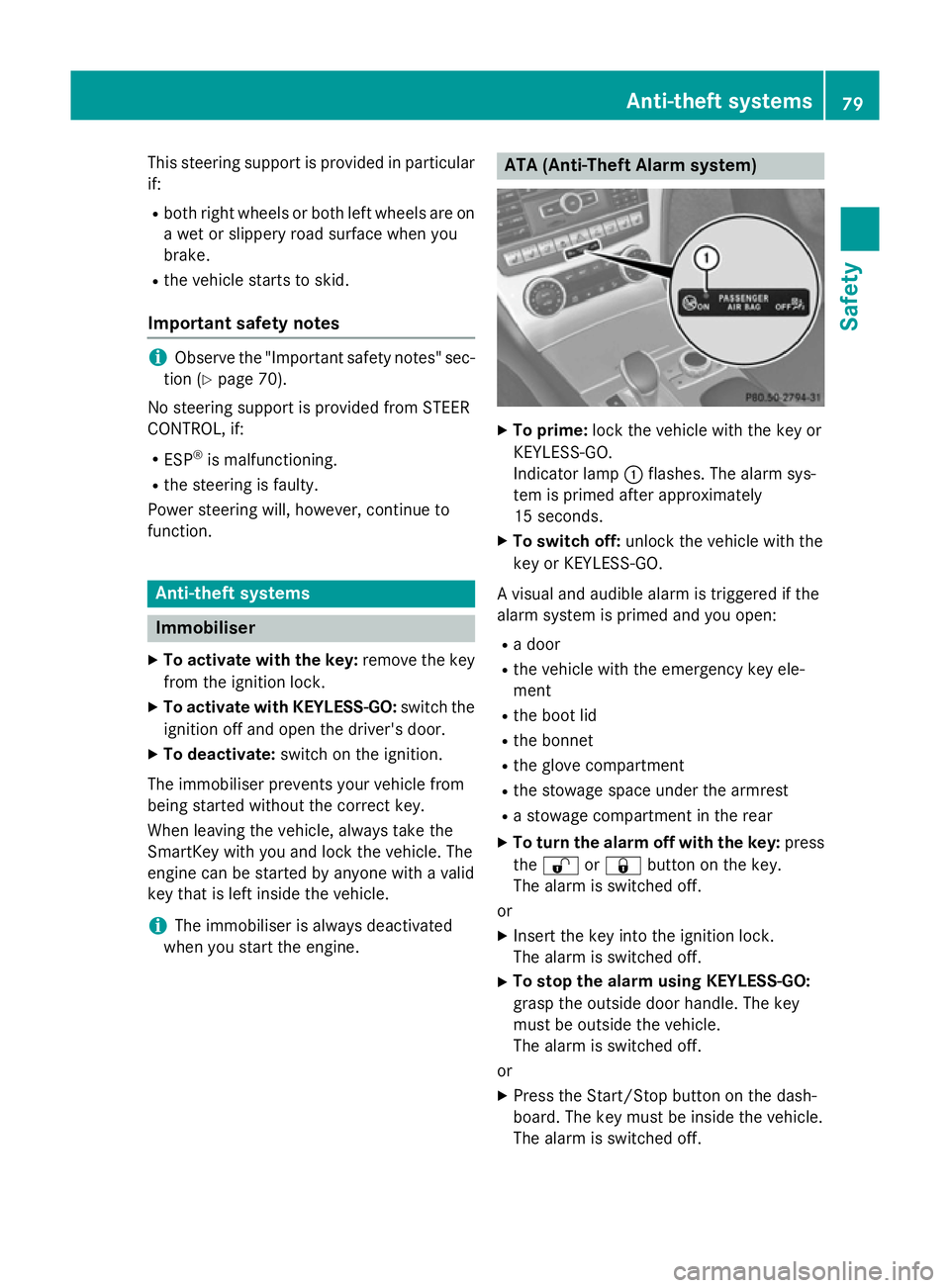
To prime: lock the vehicle with the key or
KEYLESS-GO.
Indicator lamp :flashes. The alarm sys-
tem is primed after approximately
15 seconds.
X To switch off: unlock the vehicle with the
key or KEYLESS-GO.
A visual and audible alarm is triggered if the
alarm system is primed and you open:
R a door
R the vehicle with the emergency key ele-
ment
R the boot lid
R the bonnet
R the glove compartment
R the stowage space under the armrest
R a stowage compartment in the rear
X To turn the alarm off with the key: press
the % or& button on the key.
The alarm is switched off.
or
X Insert the key into the ignition lock.
The alarm is switched off.
X To stop the alarm using KEYLESS-GO:
grasp the outside door handle. The key
must be outside the vehicle.
The alarm is switched off.
or
X Press the Start/Stop button on the dash-
board. The key must be inside the vehicle.
The alarm is switched off. Anti-theft systems
79Safety Z
Page 139 of 637
4
° Continuous wipe, slow
5 ¯ Continuous wipe, fast
B í Single wipe/ îto wipe the wind-
screen using washer fluid
X Turn the key to position 1or 2in the ignition
lock (Y page 155).
X Turn the combination switch to the corre-
sponding position.
In the ÄorÅ position, the appropriate
wiping frequency is set automatically accord- ing to the intensity of the rain. In the Å
position, the rain sensor is more sensitive
than in the Äposition, causing the wind-
screen wipers to wipe more frequently.
If the wiper blades are worn, the windscreen
will no longer be wiped properly. This could
prevent you from observing the traffic condi-
tions, thereby causing an accident.
i The vehicle is equipped with the MAGIC
VISION CONTROL wipe/wash system. The
washer fluid is fed through the wiper blades
and when the screen is wiped with washer
fluid î, the water is emitted directly
from the blades. Replacing the wiper blades
Important safety notes G
WARNING
If the windscreen wipers begin to move while
you are changing the wiper blades, you can be trapped by the wiper arm. There is a risk of
injury.
Always switch off the windscreen wipers and
ignition before changing the wiper blades.
! To avoid damaging the windscreen wiper
blades, make sure that you touch only the
wiper arm of the windscreen wiper.
! Never open the bonnet if a windscreen
wiper arm has been folded away from the
windscreen. Never fold a windscreen wiper arm without
a wiper blade back onto the windscreen.
Hold the windscreen wiper arm firmly when you change the wiper blade. If you release
the windscreen wiper arm without a wiper
blade and it falls onto the windscreen, the
windscreen may be damaged by the force
of the impact.
Mercedes-Benz recommends that you have the wiper blades changed at a qualified
specialist workshop.
! Always position the windscreen wiper
arms vertically before folding them away
from the windscreen. By doing so, you will
avoid damage to the bonnet.
Replacing the windscreen wiper blades Moving the wiper blades to a vertical posi-
tion
On vehicles without KEYLESS-GO:
X Turn the key to position 1or 2in the ignition
lock.
X Set the windscreen wipers to posi-
tion °.
X When the wiper arms have reached a ver-
tical position, turn the key to position 0and
remove it from the ignition lock.
X Fold the wiper arm away from the wind-
screen until it engages.
On vehicles with KEYLESS-GO: X Switch off the engine.
X Remove your foot from the brake pedal.
X Set the windscreen wipers to posi-
tion °.
X Press the Start/Stop button repeatedly
until the windscreen wipers start.
X When the wiper arms have reached a ver-
tical position, press the Start/Stop button.
X Fold the wiper arm away from the wind-
screen until it engages. 136
Windscreen wipersLights and windscreen wipers
Page 153 of 637
Residual heat is deactivated automatically:
R after approximately 30 minutes
R when the ignition is switched on
R if the battery voltage drops Adjusting the air vents
Important safety notes
G
WARNING
Very hot or very cold air can flow from the air vents. This could result in burns or frostbite in the immediate vicinity of the air vents. There
is a risk of injury.
Make sure that all vehicle occupants always
maintain a sufficient distance to the air out-
lets. If necessary, redirect the airflow to
another area of the vehicle interior. G
WARNING
When AIRSCARF is switched on, very hot air
can flow from the vents in the head restraints. This could result in burns in the immediate
vicinity of the air vents. There is a risk of injury.
Reduce the heater output before it becomes
too hot.
In order to ensure the direct flow of fresh air
through the air vents into the vehicle interior, please observe the following notes:
R keep the air inlet grille on the bonnet and in
the engine compartment on the front-
passenger side free of blockages, such as
ice, snow or leaves.
R never cover the vents or ventilation grilles
in the vehicle interior.
i You can move the adjusters for the air
vents vertically or horizontally to set the
direction of the airflow.
i Optimal climate control function is ach-
ieved by opening the air vents fully and set-
ting the adjusters to the middle position. Setting the centre air vents
X
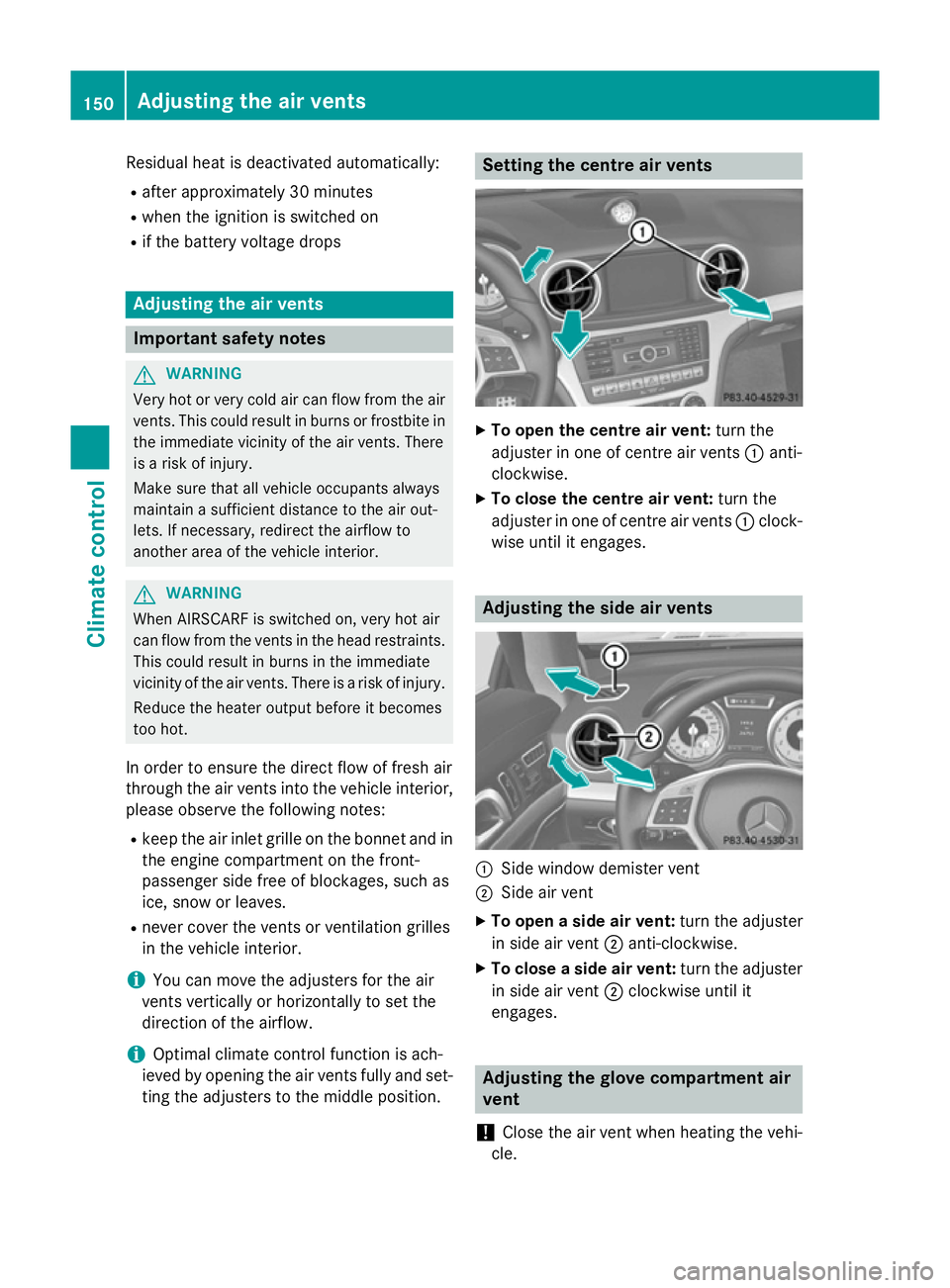
To open the centre air vent: turn the
adjuster in one of centre air vents :anti-
clockwise.
X To close the centre air vent: turn the
adjuster in one of centre air vents :clock-
wise until it engages. Adjusting the side air vents
:
Side window demister vent
; Side air vent
X To open a side air vent: turn the adjuster
in side air vent ;anti-clockwise.
X To close a side air vent: turn the adjuster
in side air vent ;clockwise until it
engages. Adjusting the glove compartment air
vent
! Close the air vent when heating the vehi-
cle. 150
Adjusting the air ventsClimate cont
rol
Page 162 of 637
General notes
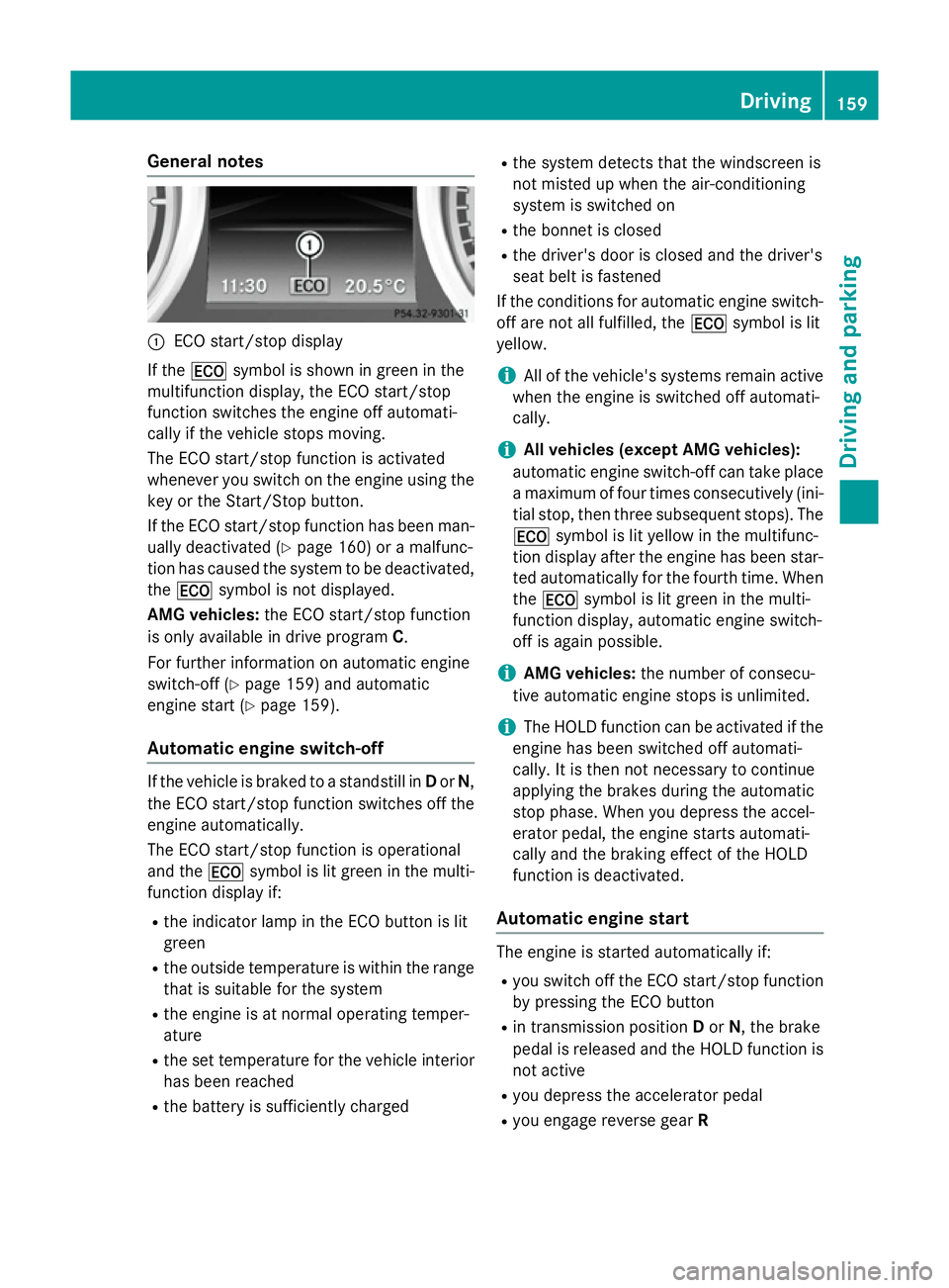
:
ECO start/stop display
If the ¤ symbol is shown in green in the
multifunction display, the ECO start/stop
function switches the engine off automati-
cally if the vehicle stops moving.
The ECO start/stop function is activated
whenever you switch on the engine using the
key or the Start/Stop button.
If the ECO start/stop function has been man- ually deactivated (Y page 160) or a malfunc-
tion has caused the system to be deactivated, the ¤ symbol is not displayed.
AMG vehicles: the ECO start/stop function
is only available in drive program C.
For further information on automatic engine
switch-off (Y page 159) and automatic
engine start (Y page 159).
Automatic engine switch-off If the vehicle is braked to a standstill in
Dor N,
the ECO start/stop function switches off the engine automatically.
The ECO start/stop function is operational
and the ¤symbol is lit green in the multi-
function display if:
R the indicator lamp in the ECO button is lit
green
R the outside temperature is within the range
that is suitable for the system
R the engine is at normal operating temper-
ature
R the set temperature for the vehicle interior
has been reached
R the battery is sufficiently charged R
the system detects that the windscreen is
not misted up when the air-conditioning
system is switched on
R the bonnet is closed
R the driver's door is closed and the driver's
seat belt is fastened
If the conditions for automatic engine switch- off are not all fulfilled, the ¤symbol is lit
yellow.
i All of the vehicle's systems remain active
when the engine is switched off automati-
cally.
i All vehicles (except AMG vehicles):
automatic engine switch-off can take place a maximum of four times consecutively (ini-
tial stop, then three subsequent stops). The
¤ symbol is lit yellow in the multifunc-
tion display after the engine has been star- ted automatically for the fourth time. Whenthe ¤ symbol is lit green in the multi-
function display, automatic engine switch-
off is again possible.
i AMG vehicles:
the number of consecu-
tive automatic engine stops is unlimited.
i The HOLD function can be activated if the
engine has been switched off automati-
cally. It is then not necessary to continue
applying the brakes during the automatic
stop phase. When you depress the accel-
erator pedal, the engine starts automati-
cally and the braking effect of the HOLD
function is deactivated.
Automatic engine start The engine is started automatically if:
R
you switch off the ECO start/stop function
by pressing the ECO button
R in transmission position Dor N, the brake
pedal is released and the HOLD function is not active
R you depress the accelerator pedal
R you engage reverse gear R Driving
159Driving and parking Z