2012 MERCEDES-BENZ GLK SUV tow bar
[x] Cancel search: tow barPage 332 of 381
i
Fully deflating the tyre may take a few
minutes.
X Screw the valve insert back into the valve.
X Screw the valve cap back on.
X Place the valve extractor back into the vehi-
cle tool kit.
X Stow the collapsible emergency spare
wheel in the emergency spare wheel well
under the luggage compartment and fasten
in place. Flat tyre
Preparing the vehicle
Your vehicle may be equipped with:
R a TIREFIT kit
R an emergency spare wheel
X Stop the vehicle as far away as possible
from traffic on solid, non-slippery and level
ground.
X Switch on the hazard warning lamps.
X Firmly depress the parking brake.
X Bring the front wheels into the straight-
ahead position.
X Vehicles with manual transmission:
engage first or reverse gear.
X Vehicles with automatic transmission:
move the DIRECT SELECT lever to P.
X Switch off the engine.
X Vehicles without KEYLESS-GO: remove
the key from the ignition lock.
X Vehicles with KEYLESS-GO: open the
driver's door.
The on-board electronics have status 0,
which is the same as the key having been
removed.
X Vehicles with KEYLESS-GO: remove the
Start/Stop button from the ignition lock
(Y page 147). X
All occupants must get out of the vehicle.
Make sure that they are not endangered as
they do so.
X Make sure that no one is near the danger
area while a wheel is being changed. Any-
one who is not directly assisting in the
wheel change should, for example, stand
behind the barrier.
X Get out of the vehicle. Pay attention to traf-
fic conditions when doing so.
X Close the driver's door.
X Place the warning triangle (Y page 326) a
suitable distance away. Observe legal
requirements. TIREFIT kit
Using the TIREFIT kit TIREFIT is a tyre sealant.
You can use TIREFIT to seal punctures of up
to 4 mm, particularly those in the tyre tread.
You can use TIREFIT at outside temperatures
down to Ò20 †. G
WARNING
In the following situations, the tyre sealant is
unable to provide sufficient breakdown assis-
tance, as it is unable to seal the tyre properly:
R there are cuts or punctures in the tyre
larger than those mentioned above.
R the wheel rim is damaged.
R you have driven at very low tyre pressures
or on a flat tyre.
There is a risk of accident.
Do not drive any further. Contact a qualified
specialist workshop.
X Do not remove any foreign objects which
have penetrated the tyre, e.g. screws or
nails.
X Remove the tyre sealant bottle, the accom-
panying "max. 80 km/h" sticker and the
tyre inflation compressor from the stowage Flat tyre
329Breakdown assistance Z
Page 334 of 381
Do not switch off the tyre inflation com-
pressor during this phase.
X Let the tyre inflation compressor run for
five minutes. The tyre should then have
attained a pressure of at least 180 kPa
(1.8 bar/26 psi).
! Do not operate the tyre inflation com-
pressor for longer than eight minutes at a
time without a break. It may otherwise
overheat.
The tyre inflation compressor can be oper-
ated again once it has cooled down.
If a pressure of 180 kP a(1 .8 ba r/26 psi) has
been achieved after five minutes, see
(Y page 331).
If a pressure of 180 kPa (1.8 ba r/26 psi) has
not been achieved after five minutes, see
(Y page 331).
Tyre pressure not reached If a pressure of 180 kPa
(1.8 ba r/26 psi) has
not been achieved after five minutes:
X Switch off the tyre inflation compressor.
X Unscrew the filler hose from the valve of
the faulty tyre.
X Very slowly drive forwards or reverse
approximately 10 m.
X Pump up the tyre again.
After a maximum of five minutes the tyre
pressure must be at least 180 kPa (1.8 bar/
26 psi). G
WARNING
If the required tyre pressure is not reached
after the specified time, the tyre is too badly
damaged. The tyre sealant cannot repair the
tyre in this instance. Damaged tyres and a tyre
pressure that is too low can significantly
impair the vehicle's braking and driving char-
acteristics. There is a risk of accident.
Do not continue driving. Contact a qualified
specialist workshop. Tyre pressure reached X
Switch off the tyre inflation compressor.
X Unscrew the filler hose from the valve of
the faulty tyre.
! After use, excess tyre sealant may run out
of the filler hose. This could cause stains.
Therefore, place the filler hose in the plastic
bag that contained the TIREFIT kit.
X Stow the tyre sealant bottle, the tyre infla-
tion compressor and the warning triangle.
X Pull away immediately. G
WARNING
A tyre temporarily sealed with tyre sealant
impairs the driving characteristics and is not
suitable for higher speeds. There is a risk of
accident.
You should therefore adapt your driving style
accordingly and drive carefully. Do not exceed
the specified maximum speed with a tyre that
has been repaired using tyre sealant.
The maximum speed for a tyre sealed with
tyre sealant is 80 km/h. The "max. 80 km/h"
sticker must be affixed to the instrument clus-
ter within the driver's field of vision.
X Stop after driving for approximately ten
minutes and check the tyre pressure with
the tyre inflation compressor.
The tyre pressure must now be at least
130 kPa (1.3 bar/19 psi). G
WARNING
If the required tyre pressure is not reached
after driving for a short period, the tyre is too
badly damaged. The tyre sealant cannot
repair the tyre in this instance. Damaged tyres
and a tyre pressure that is too low can signif-
icantly impair the vehicle's braking and driv-
ing characteristics. There is a risk of accident.
Do not continue driving. Contact a qualified
specialist workshop.
i In your vehicle, you will find a sticker with
the Mercedes-Benz Service24h telephone Flat tyre
331Breakdown assistance Z
Page 345 of 381
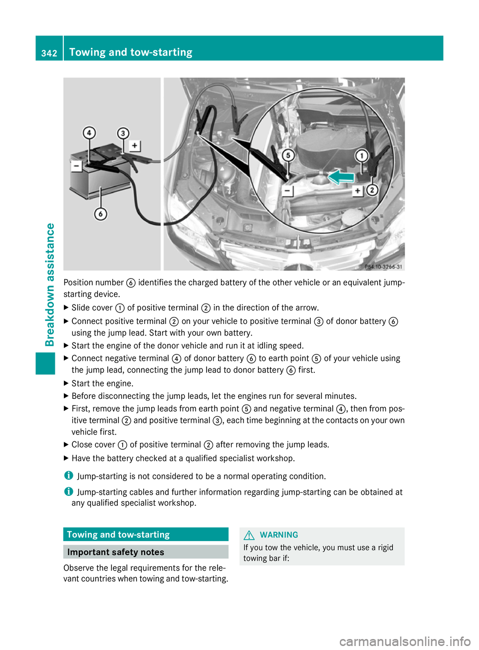
Position number
Bidentifies the charged battery of the other vehicle or an equivalent jump-
starting device.
X Slide cover :of positive terminal ;in the direction of the arrow.
X Connect positive terminal ;on your vehicle to positive terminal =of donor battery B
using the jump lead. Start with your own battery.
X Start the engine of the donor vehicle and run it at idling speed.
X Connect negative terminal ?of donor battery Bto earth point Aof your vehicle using
the jump lead, connecting the jump lead to donor battery Bfirst.
X Start the engine.
X Before disconnecting the jump leads, let the engines run for several minutes.
X First, remove the jump leads from earth point Aand negative terminal ?, then from pos-
itive terminal ;and positive terminal =, each time beginning at the contacts on your own
vehicle first.
X Close cover :of positive terminal ;after removing the jump leads.
X Have the battery checked at a qualified specialist workshop.
i Jump-starting is not considered to be a normal operating condition.
i Jump-starting cables and further information regarding jump-starting can be obtained at
any qualified specialist workshop. Towing and tow-starting
Important safety notes
Observe the legal requirements for the rele-
vant countries when towing and tow-starting. G
WARNING
If you tow the vehicle, you must use a rigid
towing bar if: 342
Towing and tow-startingBreakdown assistance
Page 346 of 381
R
the engine is not running.
R there is a brake system malfunction.
R there is a malfunction in the power supply
or the vehicle's electrical system.
The power assistance for the steering and the
brake force booster do not work when the
engine is not running. You will need more
force to steer and brake, you may have to
depress the brake pedal with maximum force.
Before towing away, make sure that the steer-
ing can be moved and is not locked.
If you tow or tow-start another vehicle, its
weight must not exceed the maximum per-
missible gross vehicle weight of your vehicle. G
WARNING
The vehicle is braked when the HOLD function
or DISTRONIC PLUS is activated. Therefore,
deactivate HOLD and DISTRONIC PLUS if the
vehicle is to be towed.
It is better to have the vehicle transported
than to have it towed.
! You may tow the vehicle for a maximum
of 50km. A towing speed of 50 km/h must
not be exceeded.
For towing distances over 50 km, the entire
vehicle must be lifted up and transported.
! Only secure the tow rope or towing bar to
the towing eyes. The vehicle may otherwise
be damaged.
! Do not use the towing eye for recovery,
as this could damage the vehicle. If in
doubt, recover the vehicle with a crane.
! Pull away smoothly when towing away or
tow-starting a vehicle. If the tractive power
is too high, the vehicles could be damaged.
! On vehicles with KEYLESS-GO, use the
key instead of the Start/Stop button. Turn
the key to position 2in the ignition lock and
shift the automatic transmission to N.
Then, turn the key back to 0and leave it in
the ignition lock. When towing a vehicle with an automatic
transmission, the transmission must be in
position
N.
The battery must be connected and charged.
Otherwise, you:
R cannot turn the key in the ignition lock to
position 2
R cannot shift the transmission to position
N on vehicles with automatic transmission
i Deactivate the automatic locking feature
(Y page 83). You could otherwise be locked
out when pushing or towing the vehicle.
Deactivate tow-away protection
(Y page 72) before the vehicle is towed. Fitting/removing the towing eye
Fitting the towing eye Vehicles with a trailer tow hitch: if you intend
to use the vehicle for towing, fit the ball cou-
pling (Y
page 217) and connect the towbar to
it.
X Remove the towing eye from the vehicle
tool kit ( Ypage 327). G
WARNING
The exhaust tail pipe may be hot. You could
burn yourself if you touch the tail pipe. Be
particularly careful when removing the rear
cover.
The mountings for the removable towing eyes
are located in the bumpers. They are at the
front and at the rear, under the covers. Towing and tow-starting
343Breakdown assistance Z
Page 349 of 381

X
Switch on the hazard warning lamps
(Y page 114).
X Fit the towing eye (Y page 343).
X Secure the rigid towing bar or the towing
rope.
X Depress and hold the brake pedal.
X Turn the key to position 2in the ignition
lock.
X Depress the clutch pedal and keep it
depressed.
X Engage neutral.
X Release the brake pedal.
X Tow-start the vehicle.
X Engage second gear.
X Release the clutch pedal slowly; do not
depress the accelerator pedal while doing
so.
The engine is started.
X Depress the clutch pedal and shift to neu-
tral.
X Stop at a suitable place.
X Depress the parking brake.
X Remove the rigid towing bar or towing rope.
X Remove the towing eye (Y page 344).
X Switch off the hazard warning lamps. Electrical fuses
Important safety notes
G
WARNING
Only use fuses that have been approved for
Mercedes-Benz vehicles and which have the
correct fuse rating for the systems con-
cerned. Do not attempt to repair or bridge
faulty fuses. Using fuses which have not been
approved or attempting to repair or bridge
faulty fuses could cause the fuse to be over-
loaded and result in a fire. Have the cause
traced and rectified at a qualified specialist
workshop.
! Only use fuses that have been approved
for Mercedes-Benz vehicles and which have the correct fuse rating for the system
concerned. Otherwise, components or sys-
tems could be damaged.
The fuses in your vehicle serve to disconnect
faulty circuits. If a fuse blows, all the compo-
nents on the circuit and their functions will
fail.
Blown fuses must be replaced with fuses of
the same rating, which you can recognise by
the colour and fuse rating. The fuse ratings
are listed in the fuse allocation chart.
If the newly inserted fuse also blows, have the
cause traced and rectified at a qualified spe-
cialist workshop, e.g. a Mercedes-Benz
Service Centre. Before replacing a fuse
X Secure the vehicle against rolling away
(Y page 164).
X Switch off all electrical consumers.
X Turn the key to position 0in the ignition
lock and remove it (Y page 147).
or
X On vehicles with KEYLESS-GO, make sure
the ignition is switched off (Y page 147).
All indicator lamps in the instrument cluster
must be off.
The fuses are located in various fuse boxes:
R fuse box on the driver's side of the dash-
board
R fuse box in the engine compartment on the
left-hand side of the vehicle, when viewed
in the direction of travel
R fuse box in the stowage well under the lug-
gage compartment floor on the right-hand
side of the vehicle, when viewed in the
direction of travel
The fuse allocation chart is located in the
vehicle tool kit in the stowage compartment
under the luggage compartment floor
(Y page 327). 346
Electrical fusesBreakdown assistance
Page 377 of 381
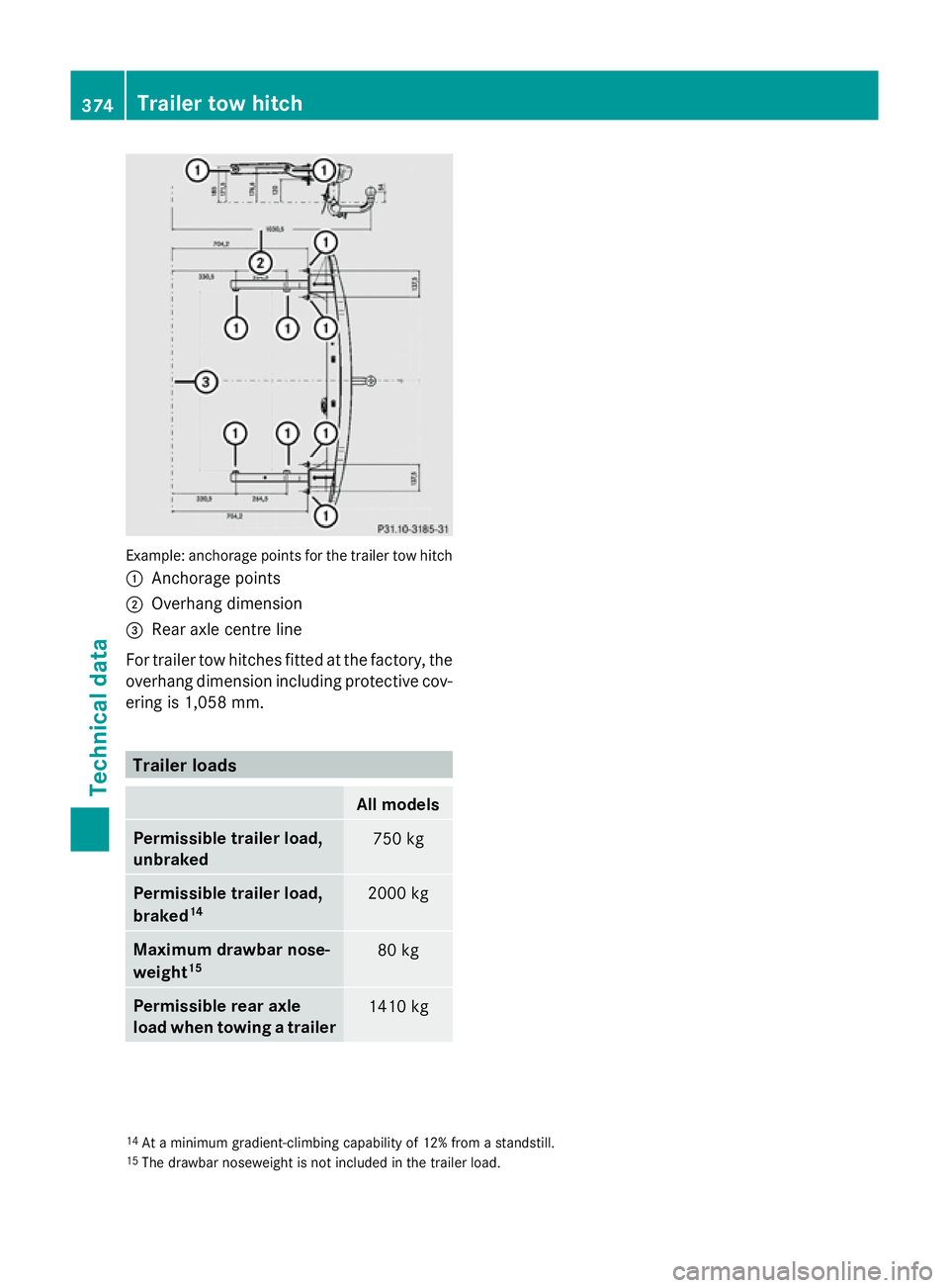
Example: anchorage points for the trailer tow hitch
: Anchorage points
; Overhang dimension
= Rear axle centre line
For trailer tow hitches fitted at the factory, the
overhang dimension including protective cov-
ering is 1,058 mm. Trailer loads
All models
Permissible trailer load,
unbraked
750 kg
Permissible trailer load,
braked
14 2000 kg
Maximum drawbar nose-
weight
15 80 kg
Permissible rear axle
load when towing a trailer
1410 kg
14
At a minimum gradient-climbing capability of 12% from a standstill.
15 The drawbar noseweight is not included in the trailer load. 374
Trailer tow hitchTechnical data