2012 MERCEDES-BENZ E-CLASS ESTATE boot
[x] Cancel search: bootPage 326 of 457
face
;has reached the desired position
and the box is the desired size.
X To raise the load surface: press switch
=.
Load surface ;of the box moves up auto-
matically.
X To stow the box: push the box in by han-
dle :all the way to the stop.
Removing and fitting X
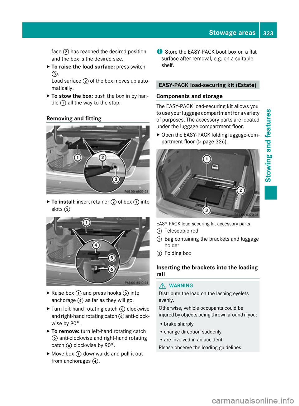
To install: insert retainer ;of box :into
slots = X
Raise box :and press hooks Ainto
anchorage ?as far as they will go.
X Turn left-hand rotating catch Bclockwise
and right-hand rotating catch Banti-clock-
wise by 90°.
X To remove: turn left-hand rotating catch
B anti-clockwise and right-hand rotating
catch Bclockwise by 90°.
X Move box :downwards and pull it out
from anchorages ?. i
Store the EASY-PACK boot box on a flat
surface after removal, e.g. on a suitable
shelf. EASY-PACK load-securing kit (Estate)
Components and storage The EASY-PACK load-securing kit allows you
to use you
rluggage compartmen tfor a variety
of purposes. The accessory parts are located
under the luggage compartment floor.
X Open the EASY-PACK folding luggage-com-
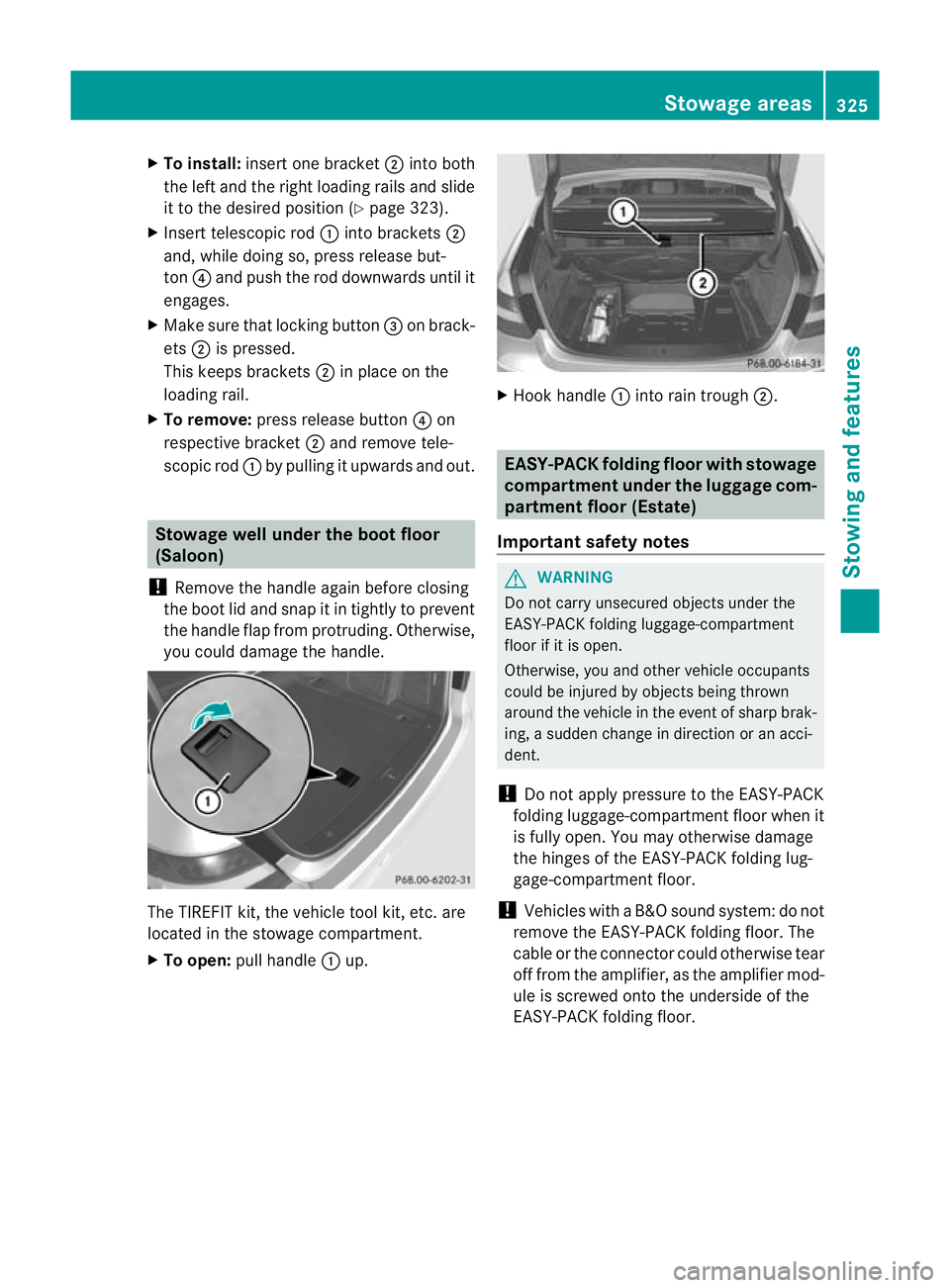
partment floor (Y page 326). EASY-PACK load-securing kit accessory parts
:
Telescopic rod
; Bag containing the brackets and luggage
holder
= Folding box
Inserting the brackets into the loading
rail G
WARNING
Distribute the load on the lashing eyelets
evenly.
Otherwise, vehicle occupants could be
injured by objects being thrown around if you:
R brake sharply
R change direction suddenly
R are involved in an accident
Please observe the loading guidelines. Stowage areas
323Stowing and features Z
Page 328 of 457
X
To install: insert one bracket ;into both
the left and the right loading rails and slide
it to the desired positio n(Ypage 323).
X Insert telescopic rod :into brackets ;
and, while doing so, press release but-
ton ?and push the rod downwards until it
engages.
X Make sure that locking button =on brack-
ets ;is pressed.
This keeps brackets ;in place on the
loading rail.
X To remove: press release button ?on
respective bracket ;and remove tele-
scopic rod :by pulling it upwards and out. Stowage well under the boot floor
(Saloon)
! Remove the handle again before closing
the boot lid and snap it in tightly to prevent
the handle flap from protruding. Otherwise,
you could damage the handle. The TIREFIT kit, the vehicle tool kit
,etc. are
located in the stowage compartment.
X To open: pull handle :up. X
Hoo khandle :into rain trough ;. EASY-PACK folding floor with stowage
compartment under th
eluggag ecom-
partment floor (Estate)
Important safety notes G
WARNING
Do not carry unsecured objects under the
EASY-PACK folding luggage-compartment
floo rifiti s open.
Otherwise, you and other vehicle occupants
could be injured by objects being thrown
around the vehicle in the event of sharp brak-
ing, a sudden change in direction or an acci-
dent.
! Do not apply pressure to the EASY-PACK
folding luggage-compartmentf loor when it
is fully open .You may otherwise damage
the hinges of the EASY-PACK folding lug-
gage-compartment floor.
! Vehicles with a B&O sound system: do not
remove the EASY-PACK folding floor. The
cable or the connector could otherwise tear
off from the amplifier, as the amplifier mod-
ule is screwed onto the underside of the
EASY-PACK folding floor. Stowage areas
325Stowing and features Z
Page 330 of 457
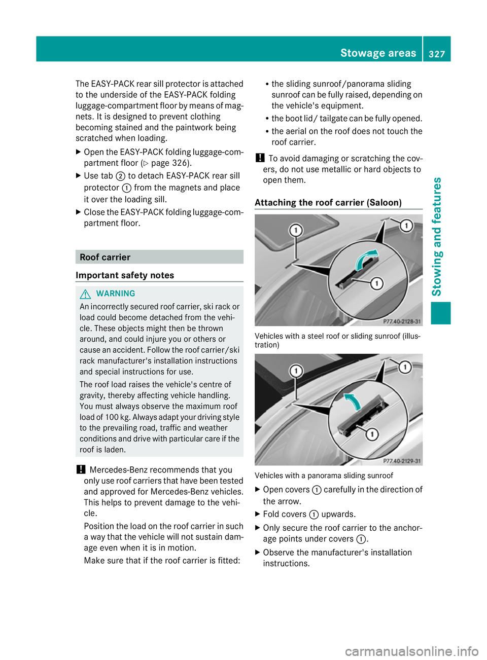
The EASY-PACK rear sill protector is attached
to the underside of the EASY-PACK folding
luggage-compartment floor by means of mag-
nets. It is designed to prevent clothing
becoming stained and the paintwork being
scratched when loading.
X Open the EASY-PACK folding luggage-com-
partment floor (Y page 326).
X Use tab ;to detach EASY-PACK rear sill
protector :from the magnets and place
it over the loading sill.
X Close the EASY-PACK folding luggage-com-
partment floor. Roof carrier
Important safety notes G
WARNING
An incorrectly secured roof carrier, ski rack or
load could become detached from the vehi-
cle. These objects might then be thrown
around, and could injure you or others or
cause an accident .Follow the roof carrier/ski
rack manufacturer's installation instructions
and special instructions for use.
The roof load raises the vehicle's centre of
gravity, thereby affecting vehicle handling.
You must always observe the maximum roof
load of 100 kg. Always adapt your driving style
to the prevailing road, traffic and weather
conditions and drive with particular care if the
roof is laden.
! Mercedes-Benz recommends that you
only use roof carriers that have been tested
and approved for Mercedes-Benz vehicles.
This helps to prevent damage to the vehi-
cle.
Position the load on the roof carrier in such
a way that the vehicle will not sustain dam-
age even when it is in motion.
Make sure that if the roof carrier is fitted: R
the sliding sunroof/panorama sliding
sunroof can be fully raised, depending on
the vehicle's equipment.
R the boot lid/ tailgate can be fully opened.
R the aerial on the roof does not touch the
roof carrier.
! To avoid damaging or scratching the cov-
ers, do not use metallic or hard objects to
open them.
Attaching the roof carrier (Saloon) Vehicles with a steel roof or sliding sunroof (illus-
tration)
Vehicles with a panorama sliding sunroof
X
Open covers :carefully in the direction of
the arrow.
X Fold covers :upwards.
X Only secure the roof carrier to the anchor-
age points under covers :.
X Observe the manufacturer' sinstallation
instructions. Stowage areas
327Stowing an d features Z
Page 363 of 457
Useful information
i This Owner's Manual describes all mod-
els, series and optional equipment for your
vehicle that were available at the time of
going to press. National variations are pos-
sible. Note that your vehicle may not be
equipped with all of the functions descri-
bed. This is also the case for systems and
functions relevant to safety.
i Read the information on qualified special-
ist workshops: (Y page 25). Where will I find...?
Warning triangle
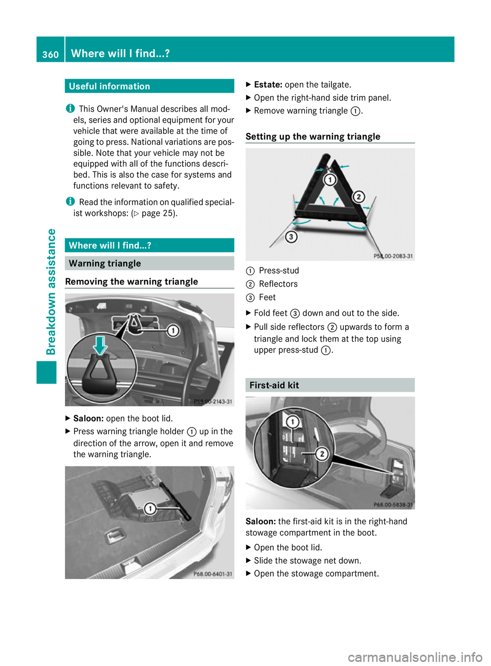
Removing the warning triangle X
Saloon: open the boot lid.
X Press warning triangle holder :up in the
direction of the arrow, open it and remove
the warning triangle. X
Estate: open the tailgate.
X Open the right-hand side trim panel.
X Remove warning triangle :.
Setting up the warning triangle :
Press-stud
; Reflectors
= Feet
X Fold feet =down and out to the side.
X Pull side reflectors ;upwards to form a
triangle and lock them at the top using
upper press-stud :. First-aid kit
Saloon:
the first-aid kit is in the right-hand
stowage compartment in the boot.
X Open the boot lid.
X Slide the stowage net down.
X Open the stowage compartment. 360
Where will I find...?Breakdown assistance
Page 364 of 457
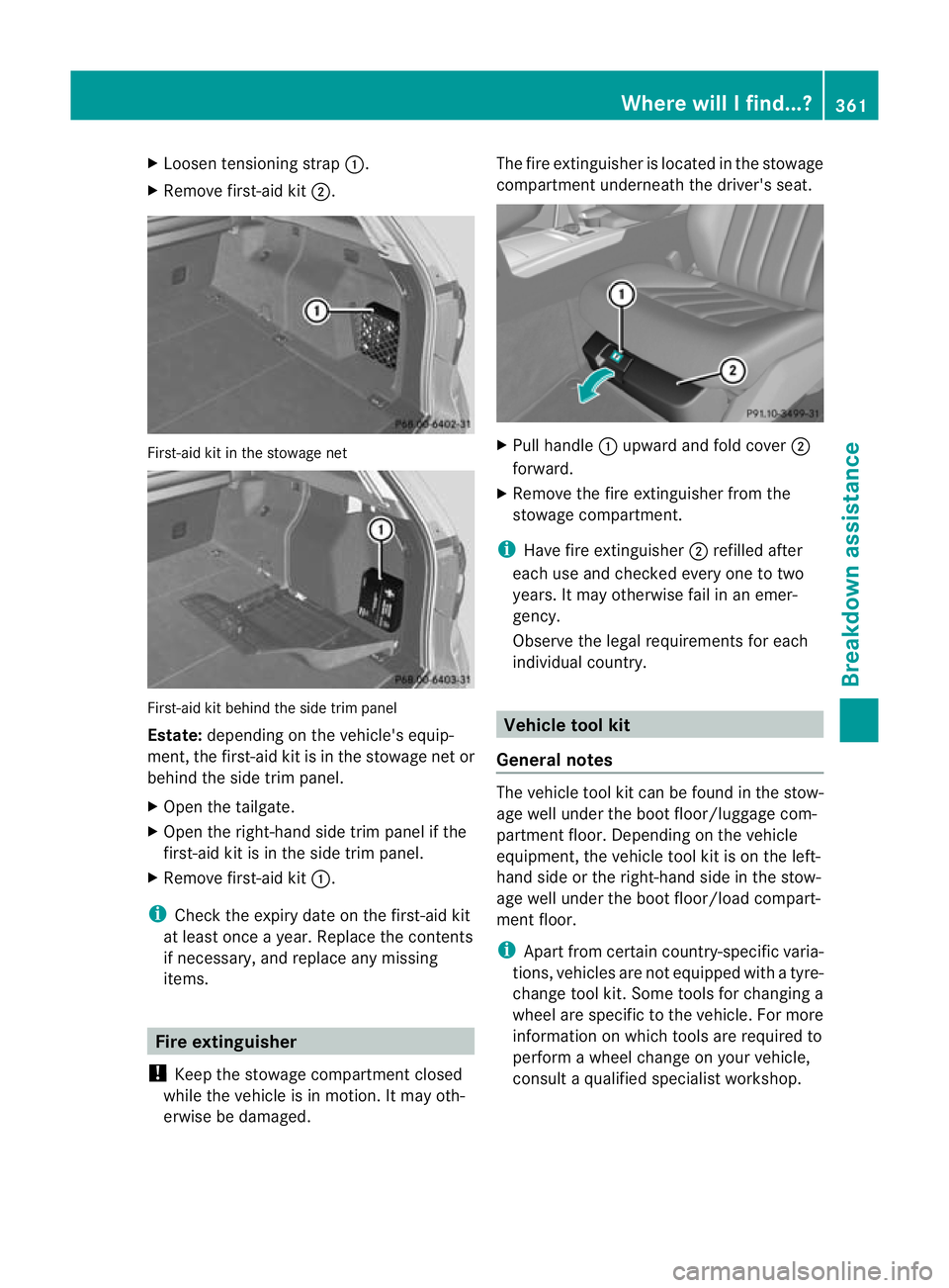
X
Loosen tensioning strap :.
X Remove first-aid kit ;.First-aid kit in the stowage net
First-aid kit behind the side trim panel
Estate:
depending on the vehicle's equip-
ment, the first-aid kit is in the stowage net or
behind the side trim panel.
X Open the tailgate.
X Open the right-hand side trim panel if the
first-aid kit is in the side trim panel.
X Remove first-aid kit :.
i Check the expiry date on the first-aid kit
at least once a year. Replace the contents
if necessary, and replace any missing
items. Fire extinguisher
! Keep the stowage compartment closed
while the vehicle is in motion. It may oth-
erwise be damaged. The fire extinguishe
ris located in the stowage
compartment underneath the driver's seat. X
Pull handle :upward and fold cover ;
forward.
X Remove the fire extinguisher from the
stowage compartment.
i Have fire extinguisher ;refilled after
each use and checked every one to two
years. It may otherwise fail in an emer-
gency.
Observe the legal requirements for each
individual country. Vehicle tool kit
General notes The vehicle tool kit can be found in the stow-
age well under the boot floor/luggage com-
partment floor. Depending on the vehicle
equipment, the vehicle tool kit is on the left-
hand side or the right-hand side in the stow-
age well under the boot floor/load compart-
ment floor.
i
Apart from certain country-specific varia-
tions, vehicles are not equipped with a tyre-
change tool kit. Some tools for changing a
wheel are specific to the vehicle. For more
information on which tools are required to
perform a wheel change on your vehicle,
consult a qualified specialist workshop. Where will I find...?
361Breakdown assistance
Page 365 of 457
Necessary wheel-changing tools can
include, for example:
R
jack
R wheel chock
R wheel wrench
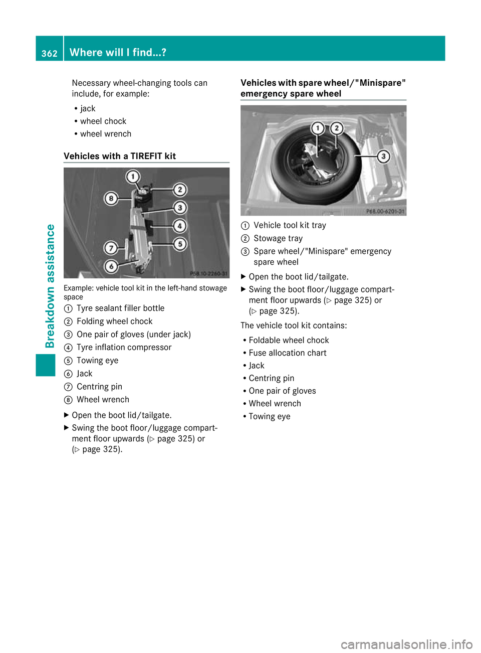
Vehicles with aTIREFIT kit Example: vehicle tool kit in the left-hand stowage
space
:
Tyre sealan tfiller bottle
; Folding wheel chock
= One pair of gloves (under jack)
? Tyre inflation compressor
A Towing eye
B Jack
C Centring pin
D Wheel wrench
X Open the boot lid/tailgate.
X Swing the boot floor/luggage compart-
men tfloor upwards (Y page 325) or
(Y page 325). Vehicles with spare wheel/"Minispare"
emergency spare wheel :
Vehicle tool kit tray
; Stowage tray
= Spare wheel/"Minispare" emergency
spare wheel
X Open the boot lid/tailgate.
X Swing the boot floor/luggage compart-
men tfloor upwards (Y page 325) or
(Y page 325).
The vehicle tool kit contains:
R Foldable wheel chock
R Fuse allocation chart
R Jack
R Centring pin
R One pair of gloves
R Wheel wrench
R Towing eye 362
Where will I find...?Breakdown assistance
Page 366 of 457
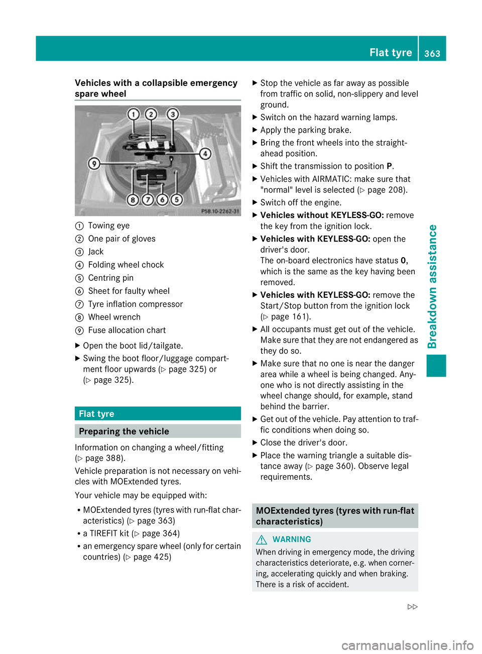
Vehicles with
acollapsible emergency
spare wheel :
Towing eye
; One pair of gloves
= Jack
? Folding wheel chock
A Centring pin
B Sheet for faulty wheel
C Tyre inflatio ncompressor
D Wheel wrench
E Fuse allocation chart
X Open the boot lid/tailgate.
X Swing the boot floor/luggage compart-
ment floor upwards (Y page 325) or
(Y page 325). Flat tyre
Preparing the vehicle
Information on changing a wheel/fitting
(Y page 388).
Vehicle preparation is not necessary on vehi-
cles with MOExtended tyres.
Your vehicle may be equipped with:
R MOExtended tyres (tyres with run-flat char-
acteristics) (Y page 363)
R a TIREFIT kit (Y page 364)
R an emergency spare wheel (only for certain
countries) (Y page 425) X
Stop the vehicle as far away as possible
from traffic on solid, non-slippery and level
ground.
X Switch on the hazard warning lamps.
X Apply the parking brake.
X Bring the front wheels into the straight-
ahead position.
X Shift the transmission to position P.
X Vehicles with AIRMATIC: make sure that
"normal" level is selected (Y page 208).
X Switch off the engine.
X Vehicles without KEYLESS-GO: remove
the key from the ignition lock.
X Vehicles with KEYLESS-GO: open the
driver's door.
The on-board electronics have status 0,
which is the same as the key having been
removed.
X Vehicles with KEYLESS-GO: remove the
Start/Stop button from the ignition lock
(Y page 161).
X All occupants must get out of the vehicle.
Make sure that they are not endangered as
they do so.
X Make sure that no one is near the danger
area while a wheel is being changed. Any-
one who is not directly assisting in the
wheel change should, for example, stand
behind the barrier.
X Get out of the vehicle. Pay attention to traf-
fic conditions when doing so.
X Close the driver's door.
X Place the warning triangle a suitable dis-
tance away (Y page 360). Observe legal
requirements. MOExtended tyres (tyres with run-flat
characteristics)
G
WARNING
When driving in emergency mode, the driving
characteristics deteriorate, e.g. when corner-
ing, accelerating quickly and when braking.
There is a risk of accident. Flat tyre
363Breakdown assistance
Z
Page 368 of 457
R
Immediately change out of clothing which
has come into contact with tyre sealant.
R If an allergic reaction occurs, seek medical
attention immediately.
! Do not operate the tyre inflation com-
pressor for longer than eight minutes at a
time withou tabreak. It may otherwise
overheat.
The tyre inflation compressor can be oper-
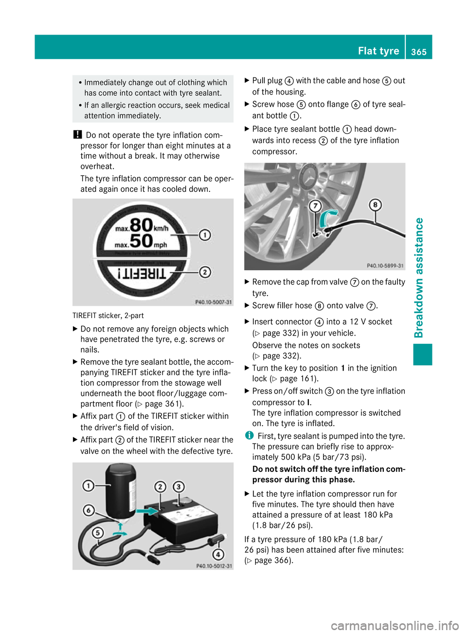
ated again once it has cooled down. TIREFIT sticker, 2-part
X
Do not remove any foreign objects which
have penetrated the tyre, e.g. screws or
nails.
X Remove the tyre sealant bottle, the accom-
panying TIREFIT sticker and the tyre infla-
tion compressor from the stowage well
underneath the boot floor/luggage com-
partment floor (Y page 361).
X Affix part :of the TIREFIT sticker within
the driver's field of vision.
X Affix part ;of the TIREFIT sticker near the
valve on the wheel with the defective tyre. X
Pull plug ?with the cable and hose Aout
of the housing.
X Screw hose Aonto flange Bof tyre seal-
ant bottle :.
X Place tyre sealant bottle :head down-
wards into recess ;of the tyre inflation
compressor. X
Remove the cap from valve Con the faulty
tyre.
X Screw filler hose Donto valve C.
X Insert connector ?into a 12 V socket
(Y page 332) in your vehicle.
Observe the notes on sockets
(Y page 332).
X Turn the key to position 1in the ignition
lock (Y page 161).
X Press on/off switch =on the tyre inflation
compressor to I.
The tyre inflation compressor is switched
on. The tyre is inflated.
i First, tyre sealant is pumped into the tyre.
The pressure can briefly rise to approx-
imately 500 kPa (5 bar/73 psi).
Do not switch off the tyre inflation com-
pressor during this phase.
X Let the tyre inflation compressor run for
five minutes. The tyre should then have
attained a pressure of at least 180 kPa
(1.8 bar/26 psi).
If a tyre pressure of 180 kPa (1.8 bar/
26 psi) has been attained after five minutes:
(Y page 366). Flat tyre
365Breakdown assistance Z