2012 MERCEDES-BENZ E-CLASS ESTATE boot
[x] Cancel search: bootPage 379 of 457
Before replacing a fuse
X Secure the vehicle against rolling away
(Y page 183).
X Switch off all electrical consumers.
X Turn the key to position 0in the ignition
lock and remove it (Y page 161).
or
X On vehicles with KEYLESS-GO, make sure
the ignition is switched off (Y page 161).
All indicator lamps in the instrument cluster
must be off.
The fuses are located in various fuse boxes:
R fuse bo xinthe engine compartmentont he
left-hand side of the vehicle, when viewed
in the direction of travel
R fuse box in the boot/luggage compartment
on the right-hand side of the vehicle, when
viewed in the direction of travel
The fuse allocation chart is located in the
vehicle tool kit in the stowage compartment
under the boot/luggage compartmentf loor
(Y page 361). Fuse box in the engine compartment
G
WARNING
Make sure that the windscreen wipers are
turned off and the key is pulled out of the igni-
tion lock before you open the cover of the fuse
box. Otherwise, the windscreen wipers and
the wiper rods above the cover could be set
in motion. This could lead to you or others
being injured by the wiper rods.
! Make sure that no moisture can enter the
fuse box when the cover is open.
! When closing the cover, make sure that it
is lying correctly on the fuse box. Moisture
seeping in or dirt could otherwise impair
the operation of the fuses.
X Make sure that the windscreen wipers are
switched off.
X Open the bonnet. X
Remove any existing moisture fro mthe
fuse box using a dry cloth.
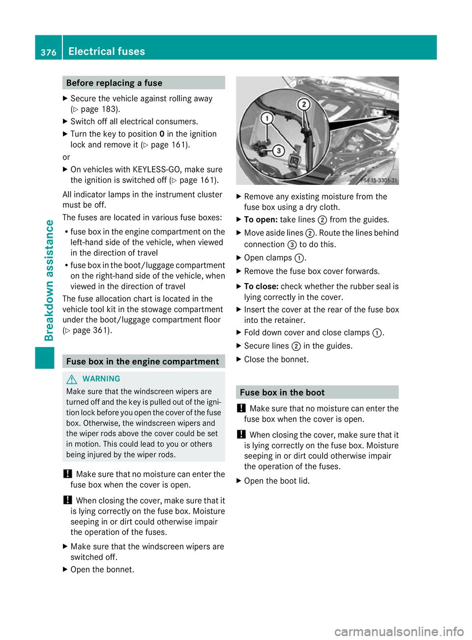
X To open: take lines ;from the guides.
X Move aside lines ;.Route the lines behind
connection =to do this.
X Open clamps :.
X Remove the fuse box cover forwards.
X To close: check whether the rubber seal is
lying correctly in the cover.
X Insert the cover at the rear of the fuse box
into the retainer.
X Fold down cover and close clamps :.
X Secure lines ;in the guides.
X Close the bonnet. Fuse box in the boot
! Make sure that no moisture can enter the
fuse box when the cover is open.
! When closing the cover, make sure that it
is lying correctly on the fuse box. Moisture
seeping in or dirt could otherwise impair
the operation of the fuses.
X Open the boot lid. 376
Electrical fusesBreakdown assistance
Page 394 of 457
R
neve rlie under the raised vehicle.
R never start the engine when the vehicle is
raised.
R never open or close a door or the boot lid/
tailgate when the vehicle is raised.
R make sure that no persons are present in
the vehicle when the vehicle is raised. X
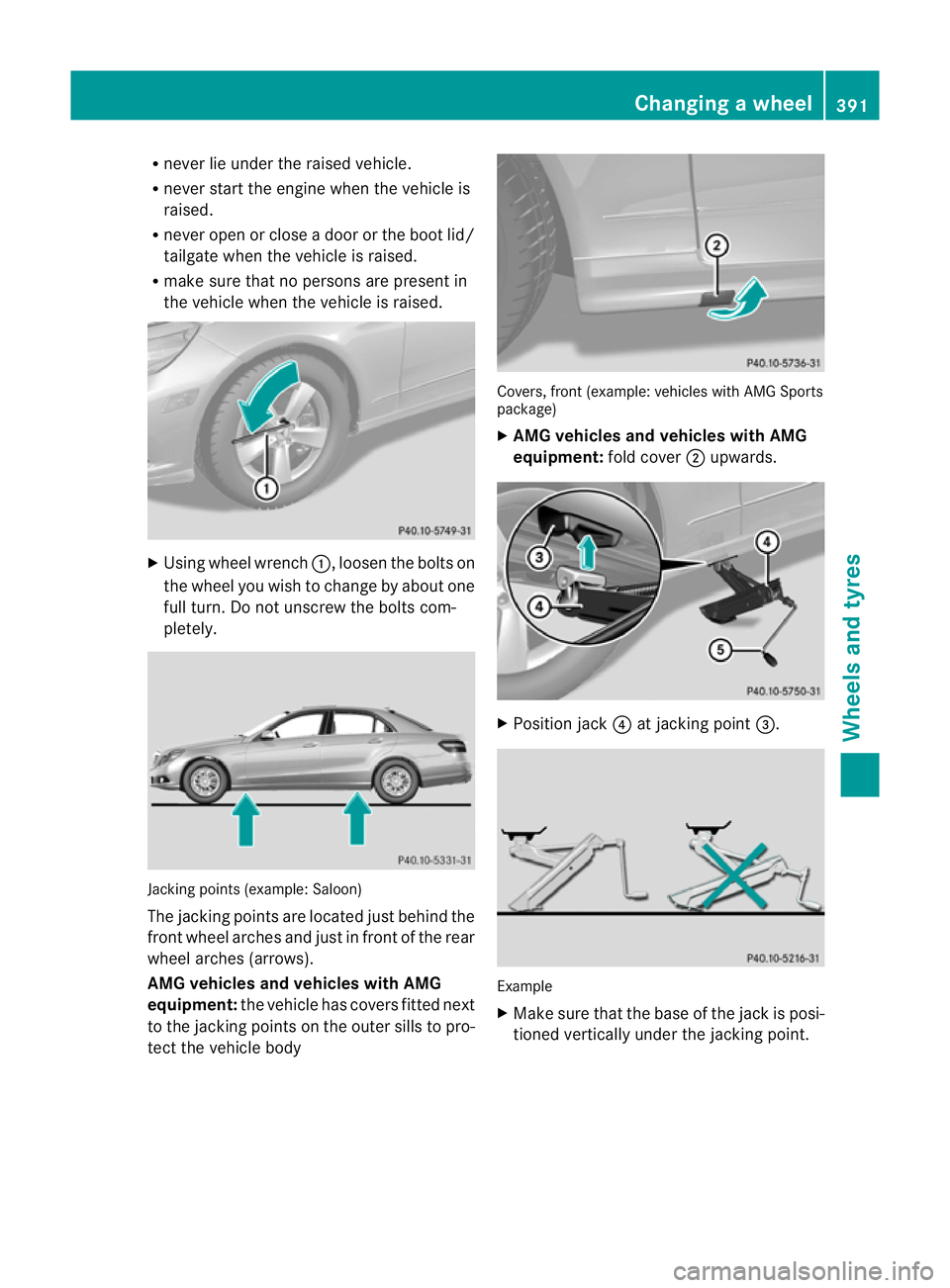
Using wheel wrench :, loosen the bolts on
the wheel you wish to change by about one
full turn. Do not unscrew the bolts com-
pletely. Jacking points (example: Saloon)
The jacking points are located just behind the
front wheel arches and just in front of the rear
wheel arches (arrows).
AMG vehicles and vehicles with AMG
equipment: the vehicle has covers fitted next
to the jacking points on the outer sills to pro-
tec tthe vehicle body Covers, front (example: vehicles with AMG Sports
package)
X
AMG vehicles and vehicles with AMG
equipment: fold cover;upwards. X
Position jack ?at jacking point =. Example
X
Make sure that the base of the jack is posi-
tioned vertically under the jacking point. Changing
awheel
391Wheels and tyres Z
Page 396 of 457
X
Tighten the wheel bolts until they are fin-
ger-tight.
X Unscrew the centring pin.
X Tighten the last wheel bolt until it is finger-
tight.
X Vehicles with acollapsible emergency
spare wheel: inflate the collapsible emer-
gency spare wheel (Y page 427).
Only then lower the vehicle.
Lowering the vehicle G
WARNING
The wheels could work loose if the wheel nuts
and bolts are not tightene dto the specified
tightening torque. There is a risk of accident.
Have the tightening torque immediately
checked at a qualified specialist workshop
after a wheel is changed.
! Vehicles with acollapsible emergency
spare wheel: Inflate the collapsible emer-
gency spare wheel using the tyre inflation
compressor before lowering th evehicle.
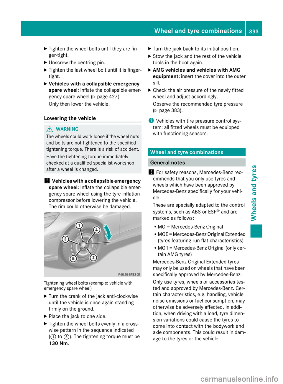
The rim could otherwise be damaged. Tightening wheel bolts (example: vehicle with
emergency spare wheel)
X Turn the crank of the jack anti-clockwise
until the vehicle is once again standing
firmly on the ground.
X Place the jack to one side.
X Tighten the wheel bolts evenly in a cross-
wise patter ninthe sequence indicated
(: toA). The tightening torque must be
130 Nm. X
Turn the jack back to its initial position.
X Stow the jack and the rest of the vehicle
tools in the boot again.
X AMG vehicles and vehicles with AMG
equipment: insert the cover into the outer
sill.
X Check the air pressure of the newly fitted
wheel and adjust accordingly.
Observe the recommended tyre pressure
(Y page 383).
i Vehicles with tire pressure control sys-
tem: all fitted wheels must be equipped
with functioning sensors. Wheel and tyre combinations
General notes
! For safety reasons, Mercedes-Ben zrec-
ommends that you only use tyres and
wheels which have been approved by
Mercedes-Benzs pecifically for your vehi-
cle.
These are specially adapted to the control
systems, such as ABS or ESP ®
and are
marked as follows:
R MO =Mercedes-BenzO riginal
R MOE =Mercedes-BenzO riginal Extended
(tyres featuring run-flat characteristics)
R MO1 =Mercedes-BenzO riginal (only cer-
tain AMG tyres)
Mercedes-Benz Original Extended tyres
may only be used on wheels that have been
specifically approved by Mercedes-Benz.
Only use tyres, wheels or accessories tes-
ted and approved by Mercedes-Benz. Cer-
tain characteristics, e.g. handling, vehicle
noise emissions or fuel consumption, may
otherwise be adversely affected. In addi-
tion, when driving with aload, tyre dimen-
sion variations could cause the tyres to
come into contact with the bodywork and
axle components.T his could result in dam-
age to the tyres or the vehicle. Wheel and tyre combinations
393Wheels and tyres Z
Page 429 of 457
sure of the removed wheel for a few
minutes. The value displayed for the moun-
ted emergency spare wheel is not the same
as the current tyre pressure of the emer-
gency spare wheel.
Removing the "Minispare" emer-
gencys
pare wheel/collapsible emer-
genc yspare wheel
Opening the stowage well Example
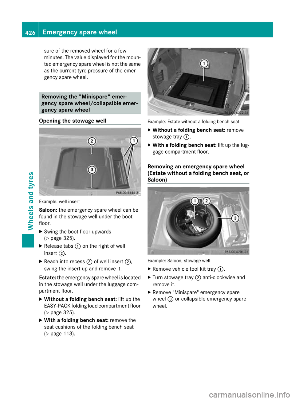
:well insert
Saloon: the emergency spare wheel can be
found in the stowage well under the boot
floor.
X Swing the boot floor upwards
(Y page 325).
X Release tabs :on the right of well
insert ;.
X Reach into recess =of well insert ;,
swing the insert up and remove it.
Estate: the emergency spare wheel is located
in the stowage well under the luggage com-
partment floor.
X Without a folding bench seat: lift up the
EASY-PACK folding load compartment floor
(Y page 325).
X With a folding bench seat: remove the
seat cushions of the folding bench seat
(Y page 113). Example: Estate without a folding bench seat
X
Without a folding bench seat: remove
stowage tray :.
X With afolding bench seat: lift up the lug-
gage compartmen tfloor.
Removing an emergency spare wheel
(Estate withou tafolding bench seat ,or
Saloon) Example: Saloon, stowage well
X
Remove vehicle tool kit tray :.
X Turn stowage tray ;anti-clockwise and
remove it.
X Remove "Minispare" emergency spare
wheel =or collapsible emergency spare
wheel. 426
Emergency spare wheelWheels and tyres
Page 430 of 457
Removing the emergenc
yspare wheel
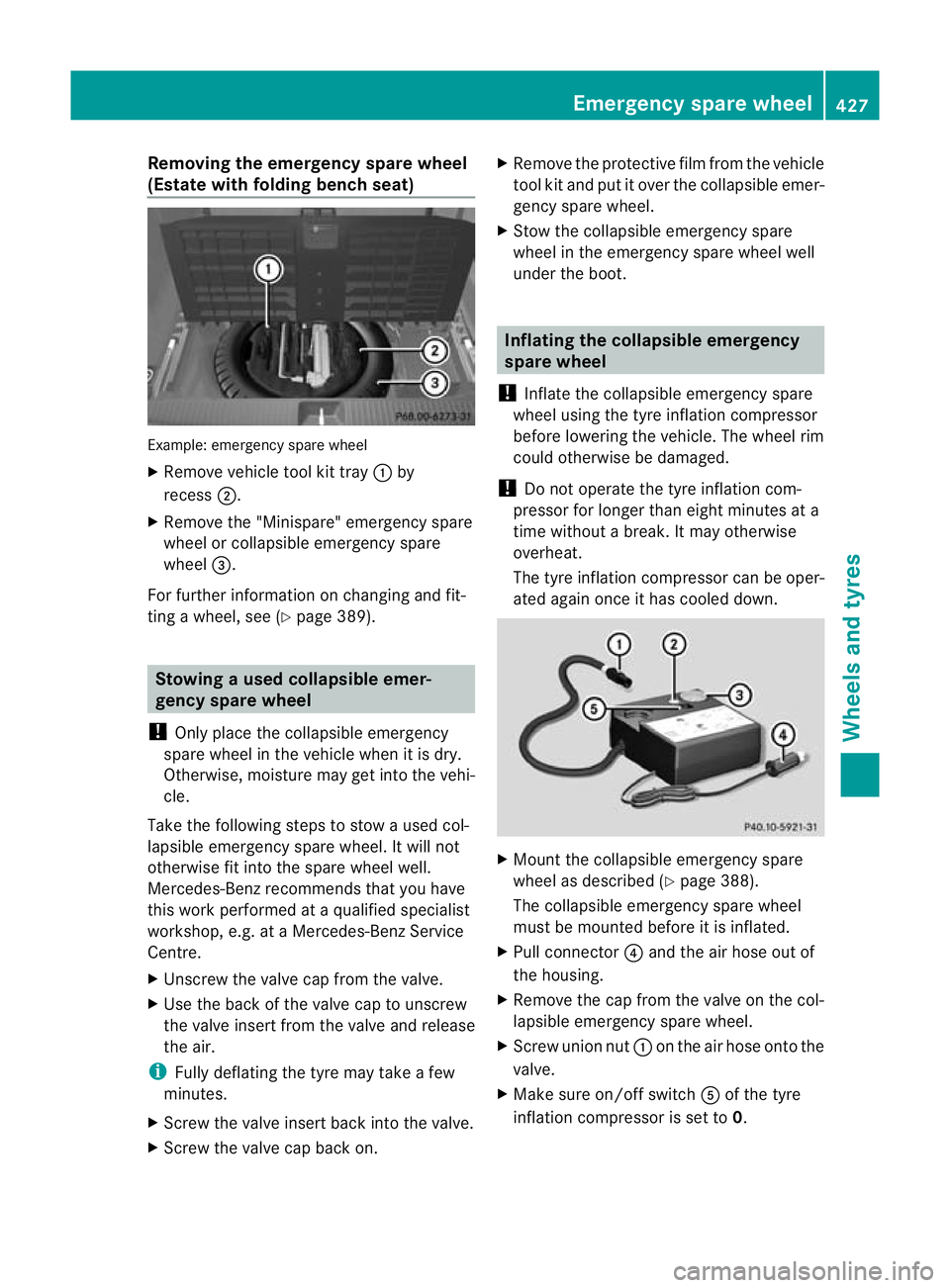
(Estate with folding benc hseat) Example: emergency spar
ewheel
X Remove vehicle tool kit tray :by
recess ;.
X Remove the "Minispare" emergency spare
wheel or collapsible emergency spare
wheel =.
For further information on changing and fit-
ting a wheel, see (Y page 389). Stowing
aused collapsible emer-
gency spare wheel
! Only place the collapsible emergency
spare wheel in the vehicle when it is dry.
Otherwise, moisture may get into the vehi-
cle.
Take the following steps to stow a used col-
lapsible emergency spare wheel. It will not
otherwise fit into the spare wheel well.
Mercedes-Benz recommends that you have
this work performed at aqualified specialist
workshop, e.g. at a Mercedes-Ben zService
Centre.
X Unscrew the valve cap from the valve.
X Use the back of the valve cap to unscrew
the valve insert from the valve and release
the air.
i Fully deflating the tyre may take a few
minutes.
X Screw the valve insert back into the valve.
X Screw the valve cap back on. X
Remove the protective film from the vehicle
tool kit and put it over the collapsible emer-
gency spare wheel.
X Stow the collapsible emergency spare
wheel in the emergency spare wheel well
under the boot. Inflating the collapsible emergency
spare wheel
! Inflate the collapsible emergency spare
wheel using the tyre inflation compressor
before lowering the vehicle. The wheel rim
could otherwise be damaged.
! Do not operate the tyre inflation com-
pressor for longer than eight minutes at a
time without a break. It may otherwise
overheat.
The tyre inflation compressor can be oper-
ated again once it has cooled down. X
Mount the collapsible emergency spare
wheel as described (Y page 388).
The collapsible emergency spare wheel
must be mounted before it is inflated.
X Pull connector ?and the air hose out of
the housing.
X Remove the cap from the valve on the col-
lapsible emergency spare wheel.
X Screw union nut :on the air hose onto the
valve.
X Make sure on/off switch Aof the tyre
inflation compressor is set to 0. Emergency spare wheel
427Wheels and tyres Z
Page 436 of 457
This is the case:
R
if they cause a change of the vehicle type
from that for which the vehicle's general
operating permit was granted
R if other road users could be endangered
R if the emission or noise levels are adversely
affected.
Always specify the vehicle identification num-
ber (VIN) (Y page 435) and the engine num-
ber (Y page 435) when ordering genuine
Mercedes-Benz parts. Vehicle electronics
Tampering with the engine electron-
ics
G
WARNING
Always have work on the engine electronics
and related components carried out at a quali-
fied specialist workshop. Otherwise, the vehi-
cle's operating safety could be affected.
! Only have work carried out on the engine
electronics and its associated parts, such
as control units, sensors and connector
leads, at a qualified specialist workshop.
Vehicle components may otherwise wear
more quickly and the vehicle's operating
permit may be invalidated. Retrofitting two-way radios and
mobile phones (RF transmitters)
G
WARNING
Incorrect retrofitting of RF transmitters can
cause the vehicle electronics to malfunction.
The vehicle's operating safety and thus your
own safety are impaired.
Have aftermarket radio frequency transmit-
ting equipment installed at a qualified spe-
cialist workshop. G
WARNING
Incorrect retrofitting of RF transmitters can
lead to increased electromagnetic radiation in
the vehicle interior. Using an exterior aerial
takes into account current scientific discus-
sions relating to the possible health hazards
that may result from electromagnetic fields.
Have aftermarket radio frequency transmit-
ting equipment installed at a qualified spe-
cialist workshop.
! The operating permit may be invalidated
if the instructions for installation and use of
RF transmitters are not observed.
In particular, the following conditions must
be complied with:
R only approved wavebands may be used.
R the maximum permissible output in
these wavebands must be complied with.
R the approved aerial positions must be
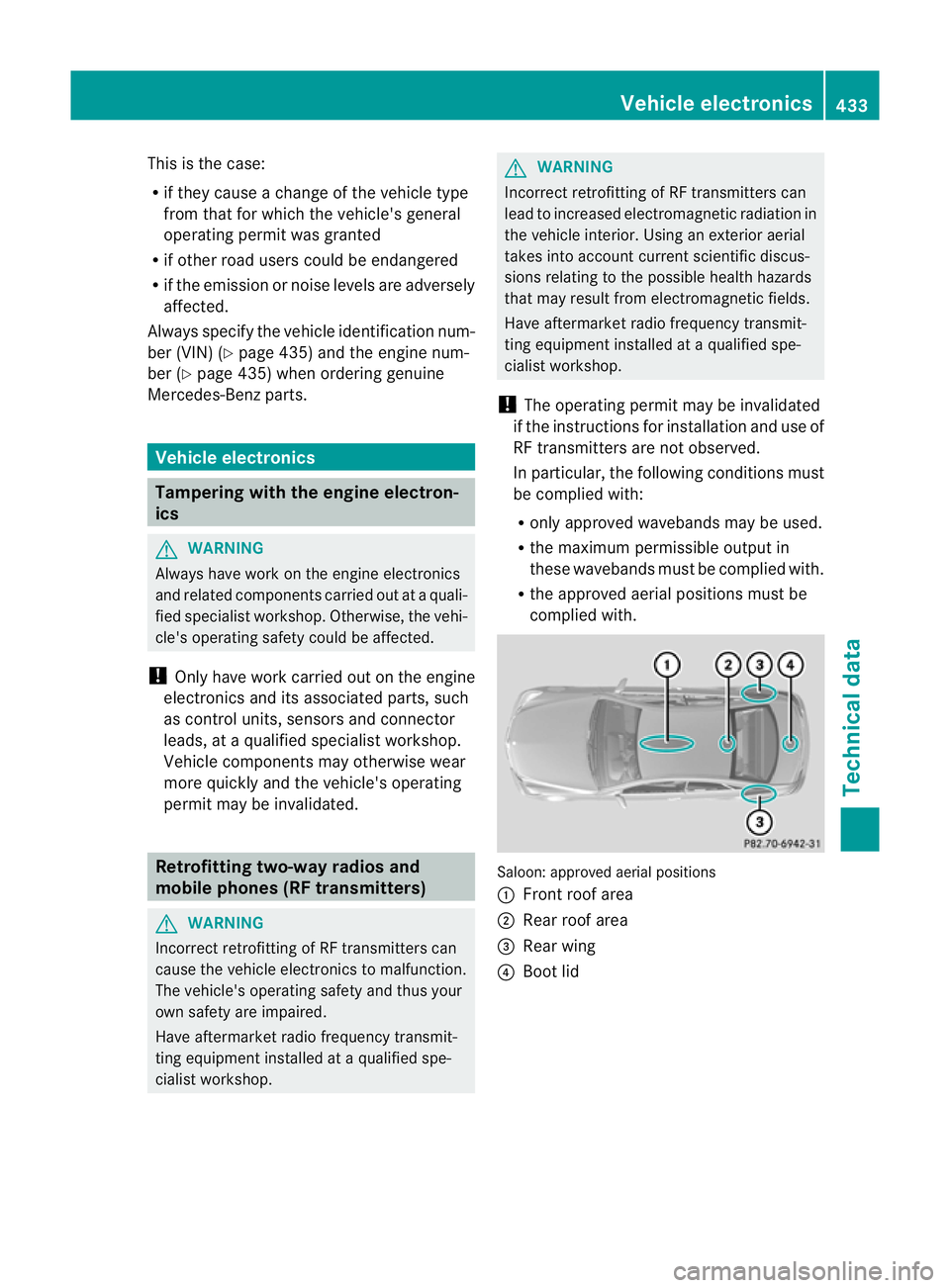
complied with. Saloon: approved aerial positions
:
Front roof area
; Rear roof area
= Rear wing
? Boot lid Vehicle electronics
433Technical data Z
Page 448 of 457
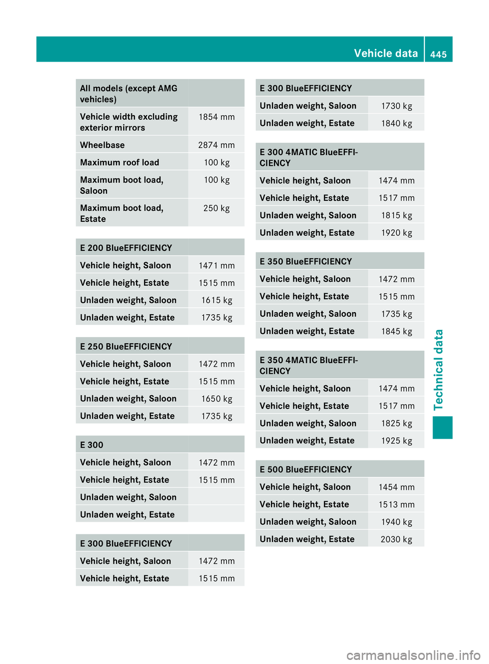
All models (excep
tAMG
vehicles) Vehicle width excluding
exterior mirrors
1854 mm
Wheelbase
2874 mm
Maximum roof load
100 kg
Maximum boot load,
Saloon
100 kg
Maximum boot load,
Estate
250 kg
E 200 BlueEFFICIENCY
Vehicle height, Saloon
1471 mm
Vehicle height, Estate
1515 mm
Unladen weight, Saloon
1615 kg
Unladen weight, Estate
1735 kg
E 250 BlueEFFICIENCY
Vehicle height, Saloon
1472 mm
Vehicle height, Estate
1515 mm
Unladen weight, Saloon
1650 kg
Unladen weight, Estate
1735 kg
E 300
Vehicle height, Saloon
1472 mm
Vehicle height, Estate
1515 mm
Unladen weight, Saloon
Unladen weight, Estate
E 300 BlueEFFICIENCY
Vehicle height, Saloon
1472 mm
Vehicle height, Estate
1515 mm E 300 BlueEFFICIENCY
Unladen weight, Saloon
1730 kg
Unladen weight, Estate
1840 kg
E 300 4MATIC BlueEFFI-
CIENCY
Vehicle height, Saloon
1474 mm
Vehicle height, Estate
1517 mm
Unladen weight, Saloon
1815 kg
Unladen weight, Estate
1920 kg
E 350 BlueEFFICIENCY
Vehicle height, Saloon
1472 mm
Vehicle height, Estate
1515 mm
Unladen weight, Saloon
1735 kg
Unladen weight, Estate
1845 kg
E 350 4MATIC BlueEFFI-
CIENCY
Vehicle height, Saloon
1474 mm
Vehicle height, Estate
1517 mm
Unladen weight, Saloon
1825 kg
Unladen weight, Estate
1925 kg
E 500 BlueEFFICIENCY
Vehicle height, Saloon
1454 mm
Vehicle height, Estate
1513 mm
Unladen weight, Saloon
1940 kg
Unladen weight, Estate
2030 kgVehicle data
445Technical data Z
Page 449 of 457
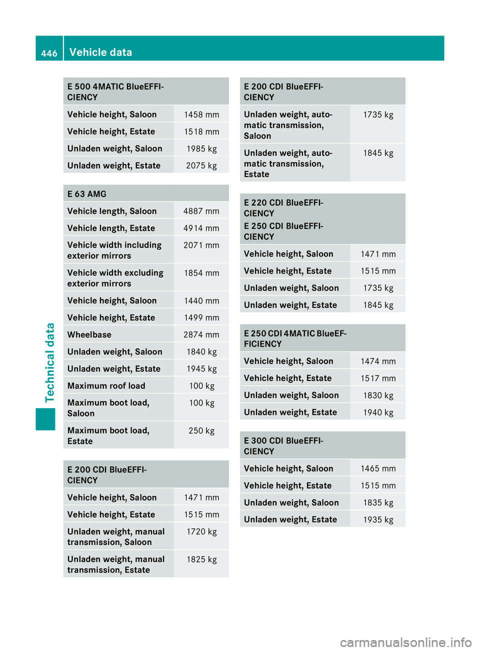
E 500 4MATIC BlueEFFI-
CIENCY
Vehicle height, Saloon
1458 mm
Vehicle height, Estate
1518 mm
Unladen weight
,Saloon 1985 kg
Unladen weight, Estate
2075 kg
E 63 AMG
Vehicle length, Saloon
4887 mm
Vehicle length, Estate
4914 mm
Vehicle width including
exterior mirrors 2071 mm
Vehicle width excluding
exterior mirrors
1854 mm
Vehicle height, Saloon
1440 mm
Vehicle height, Estate
1499 mm
Wheelbase
2874 mm
Unladen weight, Saloon
1840 kg
Unladen weight, Estate
1945 kg
Maximum roof load
100 kg
Maximum boot load,
Saloon
100 kg
Maximum boot load,
Estate
250 kg
E 200 CDI BlueEFFI-
CIENCY
Vehicle height, Saloon
1471 mm
Vehicle height, Estate
1515 mm
Unladen weight, manual
transmission ,Saloon 1720 kg
Unladen weight, manual
transmission ,Estate 1825 kg E 200 CDI BlueEFFI-
CIENCY
Unladen weight, auto-
matic transmission,
Saloon
1735 kg
Unladen weight, auto-
matic transmission,
Estate
1845 kg
E 220 CDI BlueEFFI-
CIENCY
E 250 CDI BlueEFFI-
CIENCY
Vehicle height, Saloon
1471 mm
Vehicle height, Estate
1515 mm
Unladen weight, Saloon
1735 kg
Unladen weight, Estate
1845 kg
E 250 CDI 4MATIC BlueEF-
FICIENCY
Vehicle height, Saloon
1474 mm
Vehicle height, Estate
1517 mm
Unladen weight, Saloon
1830 kg
Unladen weight, Estate
1940 kg
E 300 CDI BlueEFFI-
CIENCY
Vehicle height, Saloon
1465 mm
Vehicle height, Estate
1515 mm
Unladen weight, Saloon
1835 kg
Unladen weight, Estate
1935 kg446
Vehicle dataTechnical data