2012 MERCEDES-BENZ CLS SHOOTING BRAKE buttons
[x] Cancel search: buttonsPage 134 of 405
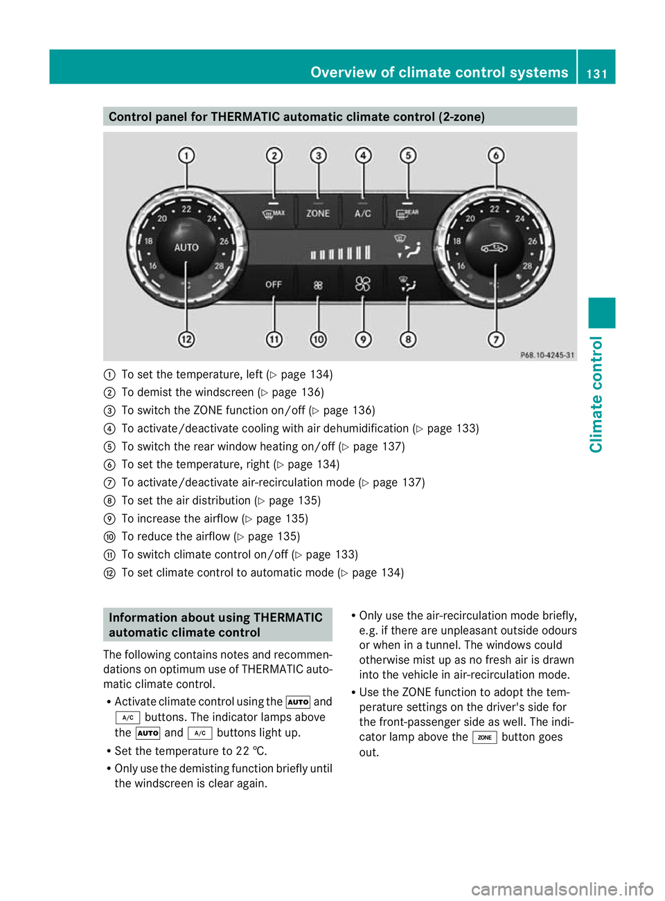
Control panel for THERMATIC automatic climate control (2-zone)
:
To set the temperature, left (Y page 134)
; To demist the windscree n(Ypage 136)
= To switch the ZONE function on/off (Y page 136)
? To activate/deactivate cooling with air dehumidification (Y page 133)
A To switch the rear window heating on/off (Y page 137)
B To set the temperature, right (Y page 134)
C To activate/deactivate air-recirculation mode (Y page 137)
D To set the air distribution (Y page 135)
E To increase the airflow (Y page 135)
F To reduce the airflow (Y page 135)
G To switch climate control on/off (Y page 133)
H To set climate control to automatic mode (Y page 134)Information about using THERMATIC
automatic climate control
The following contains notes and recommen-
dations on optimum use of THERMATIC auto-
matic climate control.
R Activate climate contro lusing the Ãand
¿ buttons. The indicator lamps above
the à and¿ buttons light up.
R Set the temperature to 22 †.
R Only use the demisting function briefly until
the windscreen is clear again. R
Only use the air-recirculation mode briefly,
e.g. if there are unpleasant outside odours
or when in a tunnel. The windows could
otherwise mist up as no fresh air is drawn
into the vehicle in air-recirculation mode.
R Use the ZONE function to adopt the tem-
perature settings on the driver's side for
the front-passenger side as well.T he indi-
cator lamp above the ábutton goes
out. Overview of climate control systems
131Climate control Z
Page 136 of 405
Information abou
tusing
THERMOTRONIC automatic climate
control
The following contains instructions and rec-
ommendations to enable you to get the most
out of your THERMOTRONIC automatic cli-
mate control.
R Activate climate control using the Ãand
¿ buttons. The indicato rlamps above
the à and¿ buttons light up.
R In automatic mode, you can also use the
ñ button to set a climate mode
(FOCUS/MEDIUM/DIFFUSE). The
MEDIUM level is recommended.
R Set the temperature to 22 †.
R Only use the demisting function briefly until
the windscree nis clear again.
R Only use the air-recirculation mode briefly,
e.g. if there are unpleasant outside odours
or when in a tunnel. The windows could
otherwise mist up as no fresh air is drawn
into the vehicle in air-recirculation mode.
R Use the ZONE function to adopt the tem-
perature settings on the driver's side for
the front-passenger side and the rear com-
partment as well.T he indicator lamp above
the á button goes out.
R Use the residual heat function if you want
to heat or ventilate the vehicle interior
when the ignition is switched off. The resid-
ual heat function can only be activated or
deactivated with the ignition switched off. Operating the climate control system
Switching climate control on/off
Points to observe before use i
If climate control is switched off, the air
supply and air circulation are also switched
off. Only use this setting for a brief period.
The windows could otherwise mist up.
i Switch on climate control primarily using
the à button (Y page 134). Switching on/off X
Turn the key to position 2in the ignition
lock.
X To switch on: press theÃbutton on
the climate control operating panel.
The indicator lamp in the Ãbutton lights
up. Airflow and air distribution are set to
automatic mode.
or
X Press the ^button.
The indicator lamp in the ^button goes
out. The previous settings are reactivated.
X To switch off: press the^button.
The indicator lamp in the ^button lights
up. Activating/deactivating the cooling
with air dehumidification function
Points to observe before use G
WARNING
If the "cooling with air dehumidification" func-
tion is deactivated, the air inside the vehicle
will not be cooled (during warm weather) or
dehumidified. The windows could mist up
more quickly. This may prevent you from
observing the traffic conditions, thereby caus-
ing an accident.
The cooling with air dehumidification function
is only available when the engine is running.
The air inside the vehicle is cooled and dehu-
midified according to the temperature selec-
ted.
Condensation may drip from the underside of
the vehicle when cooling mode is active. This
is normal and not a sign that there is a mal-
function.
i The cooling with air dehumidification
function uses refrigerant R134a. This
refrigerant does not contain chlorofluoro-
carbons, and therefore does not damage
the ozone layer. Operating the climate control system
133Climate control Z
Page 144 of 405
Setting the departure time
X
Press the ,or. button repeatedly
until the time to be changed appears in the
display.
X Press the uand^ buttons simulta-
neously.
The Îsymbol in the remote control dis-
play flashes.
X Press the ,or. button to set the
desired departure time.
i The longer you press the ,or.
button, the faster the time changes.
X Press the uand^ buttons simulta-
neously.
The new departure time is stored.
Activating the set departure time
X Press the ,or. button repeatedly
until the desired departure time appears in
the display.
X Press the ubutton.
The Ísymbol and the departure time
appearint he display.
Deactivating a set departure time
X Press the ,or. button.
The status of the auxiliary heating is shown
in the display.
X Press the .button.
The first departure time stored appears in
the display.
X Press the ^button.
The display message OFF appears in the
display.
Replacing the remote control battery G
WARNING
Batteries contain poisonous substances.
Swallowing/ingesting batteries can result in
serious personal injury or death.
Always keep batteries away from children. If
a battery is swallowed, seek immediate med-
ical attention. H
Environmental note Batteries contain pollutants.
It is illegal to dispose of them
with the household rubbish.
They must be collected sep-
arately and disposed of in an
environmentally responsible
recycling system.
Dispose of batteries in an
environmentally responsible
manner. Take discharged
batteries to a qualified spe-
cialist workshop or to a col-
lection point for used batter-
ies.
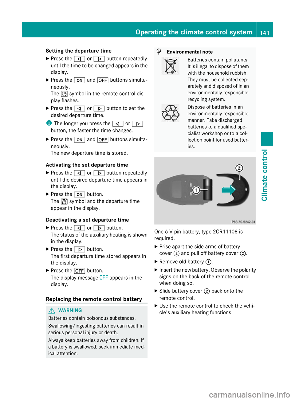
One 6 V pin battery, type 2CR11108 is
required.
X
Prise apart the side arms of battery
cover ;and pull off battery cover ;.
X Remove old battery :.
X Insert the new battery. Observe the polarity
signs on the back of the remote control
when doing so.
X Slide battery cover ;back onto the
remote control.
X Use the remote control to check the vehi-
cle's auxiliary heating functions. Operating the climate control system
141Climate control Z
Page 232 of 405
X
To activate the on-board computer: turn
the key to position 1in the ignition lock.
You can control the multifunctio ndisplay and
the settings in the on-board computer using
the buttons on the multifunction steering
wheel.
Left control panel =
; R
Calls up the menu and menu bar 9
:
Press briefly:
R
Scrolls through lists
R Selects a submenu or function
R In the Audio menu: selects a
stored station, an audio track or
a video scene
R In the Tel (telephone) menu:
switches to the phone book and
selects a name or telephone
number 9
:
Press and hold:
R
In the Audio menu: selects the
previous/next station or selects
an audio track or a video scene
using rapid scrolling
R In the Tel (Telephone) menu:
starts rapid scrolling if the phone
book is open a R
Confirms selection/display mes-
sage
R In the Tel (telephone) menu:
switches to the telephone book
and starts dialling the selected
number
R In the Audio menu: stops the
station search function at the
desired station Righ
tcontrol panel ~ R
Rejects or ends a call
R Exits telephone book/redial
memory 6 R
Makes or accepts a call
R Switches to the redial memory W
X R
Adjusts the volume 8 R
Mute Back button
%
Press briefly:
R
Back
R Switches off LINGUATRONIC;
see the separate operating
instructions
R Hides display messages/calls
up the last Trip menu function
used
R Exits the telephone book/redial
memory %
Press and hold:
R
Calls up the standard display in
the Trip menu
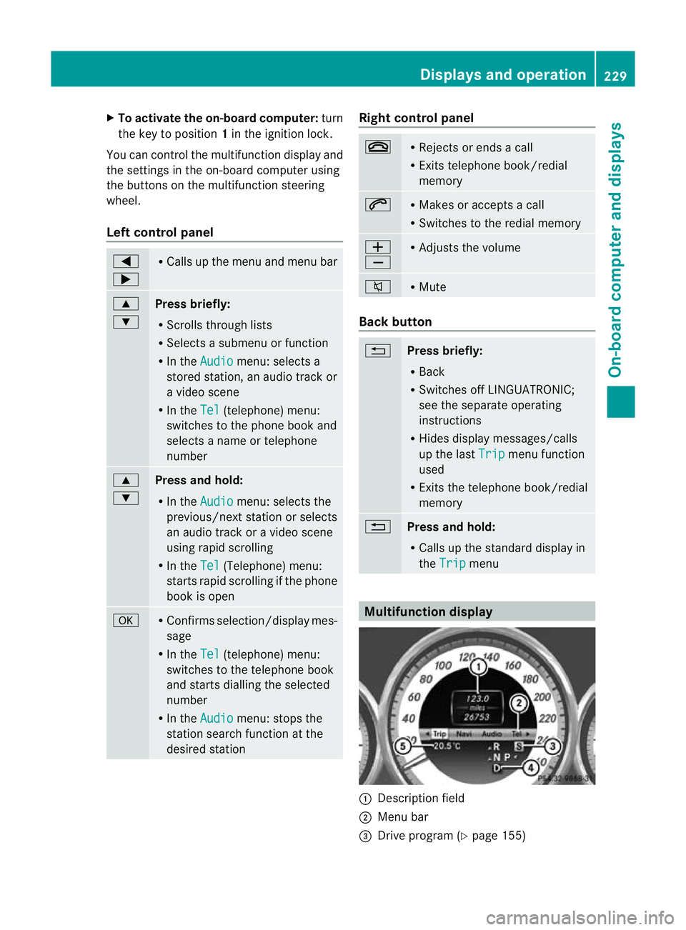
Multifunction display
:
Description field
; Menu bar
= Drive program (Y page 155) Displays and operation
229On-board computer and displays Z
Page 301 of 405
X
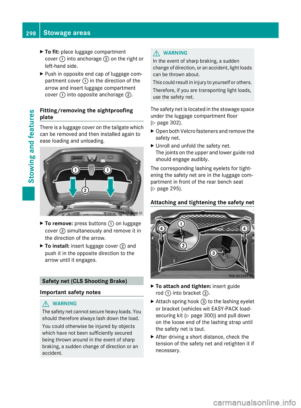
To fit: place luggage compartment
cover :into anchorage ;on the right or
left-hand side.
X Push in opposite end cap of luggage com-
partment cover :in the direction of the
arrow and insert luggage compartment
cover :into opposite anchorage ;.
Fitting/removing the sightproofing
plate There is a luggage cove
ronthe tailgate which
can be removed and then installed again to
ease loading and unloading. X
To remove: press buttons :on luggage
cover ;simultaneously and remove it in
the direction of the arrow.
X To install: insert luggage cover ;and
push it in the opposite direction to the
arrow until it engages. Safety net (CLS Shooting Brake)
Important safety notes G
WARNING
The safety net cannot secure heavy loads. You
should therefore always lash down the load.
You could otherwise be injured by objects
which have not been sufficiently secured
being thrown around in the event of sharp
braking, a sudden change of direction or an
accident. G
WARNING
In the event of sharp braking, a sudden
change of direction, or an accident, light loads
can be thrown about.
This could result in injury to yourself or others.
Therefore, if you are transporting light loads,
use the safety net.
The safety net is located in the stowage space
under the luggage compartmentf loor
(Y page 302).
X Open both Velcro fastener sand remove the
safety net.
X Unroll and unfold the safety net.
The joints on the uppe rand lowe rguide rod
should engage audibly.
The corresponding lashing eyelet sfor tight-
ening the safety net are in the luggage com-
partment in front of the rear bench seat
(Y page 295).
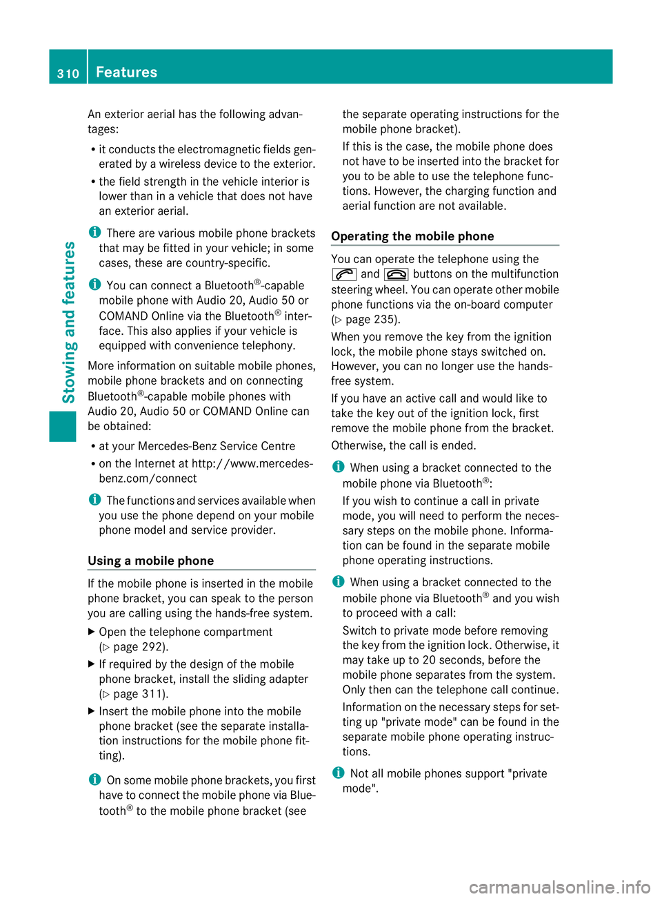
Attaching and tightening the safety net X
To attach and tighten: insert guide
rod :into bracket ;.
X Attach spring hook =to the lashing eyelet
or bracket (vehicles wit EASY-PACK load-
securing kit (Y page 300)) and pull down
on the loose end of the lashing strap until
the safety net is taut.
X After driving a short distance, check the
tension of the safety net and retighten it if
necessary. 298
Stowage areasStowing and features
Page 313 of 405
An exterio
raerial has the following advan-
tages:
R it conducts the electromagnetic fields gen-
erated by a wireless device to the exterior.
R the field strength in the vehicle interior is
lower than in a vehicle that does not have
an exterior aerial.
i There are various mobile phone brackets
that may be fitted in your vehicle; in some
cases, these are country-specific.
i You can connect a Bluetooth ®
-capable
mobile phone with Audio 20, Audio 50 or
COMAND Online via the Bluetooth ®
inter-
face. This also applies if your vehicle is
equipped with convenience telephony.
More information on suitable mobile phones,
mobile phone brackets and on connecting
Bluetooth ®
-capable mobile phones with
Audio 20, Audio 50 or COMAND Online can
be obtained:
R at your Mercedes-Benz Service Centre
R on the Internet at http://www.mercedes-
benz.com/connect
i The functions and services available when
you use the phone depend on your mobile
phone model and service provider.
Using amobile phone If the mobile phone is inserted in the mobile
phone bracket, you can speak to the person
you are calling using the hands-free system.
X
Open the telephone compartment
(Y page 292).
X If required by the desig nofthe mobile
phone bracket, install the sliding adapter
(Y page 311).
X Insert the mobile phone into the mobile
phone bracket (see the separate installa-
tion instructions for the mobile phone fit-
ting).
i On some mobile phone brackets, you first
have to connect the mobile phone via Blue-
tooth ®
to the mobile phone bracket (see the separate operating instructions for the
mobile phone bracket).
If this is the case, the mobile phone does
not have to be inserted into the bracket for
you to be able to use the telephone func-
tions. However, the charging function and
aerial function are not available.
Operating the mobile phone You can operate the telephone using the
6
and~ buttons on the multifunction
steering wheel. You can operate other mobile
phone functions via the on-board computer
(Y page 235).
When you remove the key from the ignition
lock, the mobile phone stays switched on.
However, you can no longer use the hands-
free system.
If you have an active call and would like to
take the key out of the ignition lock, first
remove the mobile phone from the bracket.
Otherwise, the call is ended.
i When using a bracket connected to the
mobile phone via Bluetooth ®
:
If you wish to continue a call in private
mode, you will need to perform the neces-
sary steps on the mobile phone. Informa-
tion can be found in the separate mobile
phone operating instructions.
i When using a bracket connected to the
mobile phone via Bluetooth ®
and you wish
to proceed with a call:
Switch to private mode before removing
the key from the ignition lock. Otherwise, it
may take up to 20 seconds, before the
mobile phone separates from the system.
Only then can the telephone call continue.
Information on the necessary steps for set-
ting up "private mode" can be found in the
separate mobile phone operating instruc-
tions.
i Not all mobile phones support "private
mode". 310
FeaturesStowing and features
Page 314 of 405
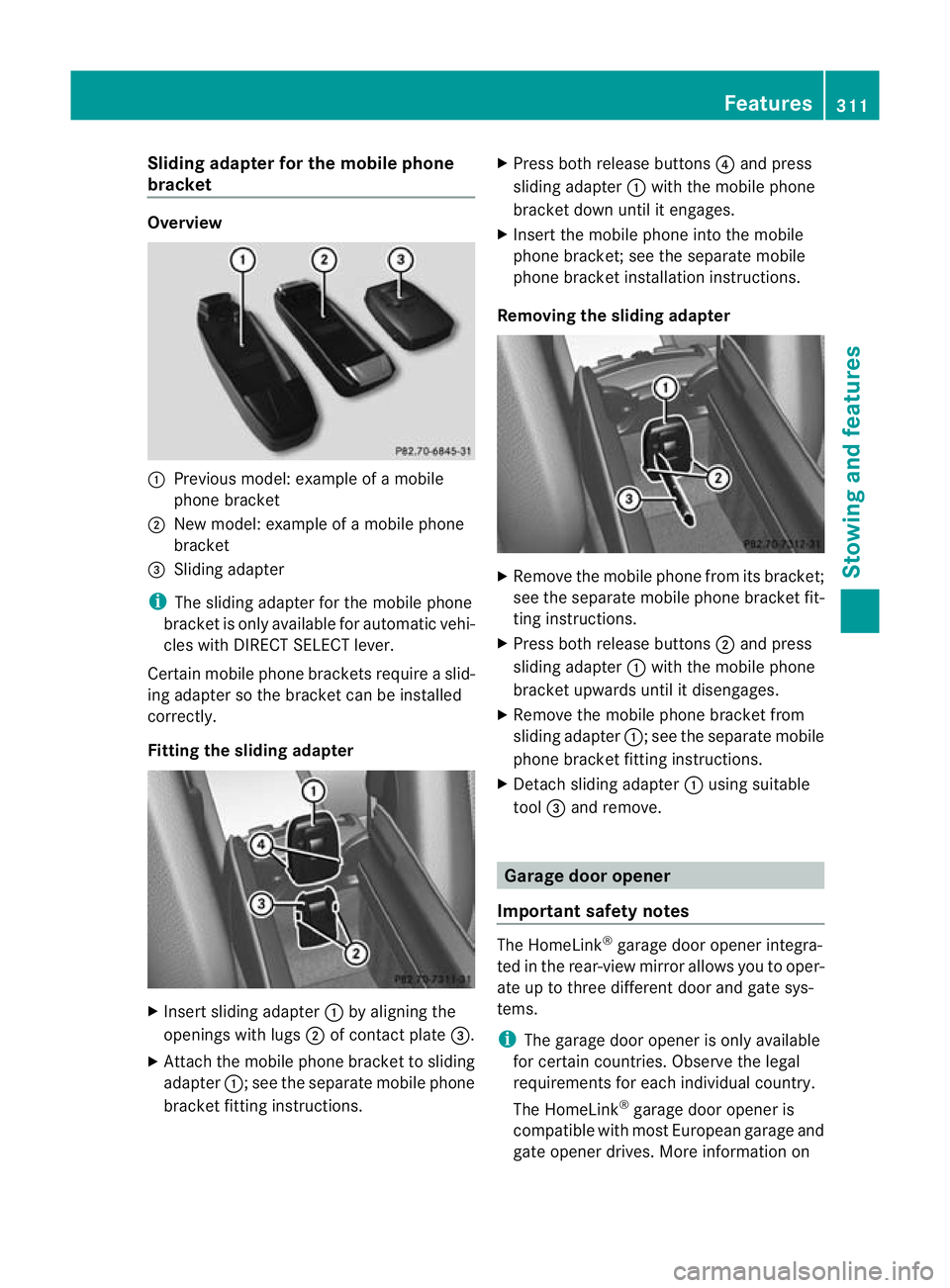
Sliding adapter for the mobile phone
bracket Overview
:
Previous model: example of a mobile
phone bracket
; New model: example of a mobile phone
bracket
= Sliding adapter
i The sliding adapter for the mobile phone
bracket is only available for automatic vehi-
cles with DIRECT SELECT lever.
Certain mobile phone brackets require a slid-
ing adapter so the bracket can be installed
correctly.
Fitting the sliding adapter X
Insert sliding adapter :by aligning the
openings with lugs ;of contact plate =.
X Attach the mobile phone bracket to sliding
adapter :; see the separate mobile phone
bracket fitting instructions. X
Press both release buttons ?and press
sliding adapter :with the mobile phone
bracket down until it engages.
X Insert the mobile phone into the mobile
phone bracket; see the separate mobile
phone bracket installation instructions.
Removing the sliding adapter X
Remove the mobile phone from its bracket;
see the separate mobile phone bracket fit-
ting instructions.
X Press both release buttons ;and press
sliding adapter :with the mobile phone
bracket upwards until it disengages.
X Remove the mobile phone bracket from
sliding adapter :; see the separate mobile
phone bracket fitting instructions.
X Detach sliding adapter :using suitable
tool =and remove. Garage door opener
Important safety notes The HomeLink
®
garage door opener integra-
ted in the rear-view mirror allows you to oper-
ate up to three different door and gate sys-
tems.
i The garage door opener is only available
for certain countries. Observe the legal
requirements for each individual country.
The HomeLink ®
garage door opener is
compatible with most European garage and
gate opener drives. More information on Features
311Stowing and features Z
Page 315 of 405
HomeLink
®
and/o rcompatible products is
available from:
R at a qualified specialised workshop
R the HomeLink ®
hotline
(0) 08000 466 354 65 (free of charge) or
+49 (0) 6838 907 277 (charges apply)
R on the Internet at:
http://www.homelink.com
Programming Programming buttons
G
WARNING
Only press the button on the integrated
garage door opener if there are no persons or
objects present within the sweep of the
garage door. Persons could otherwise be
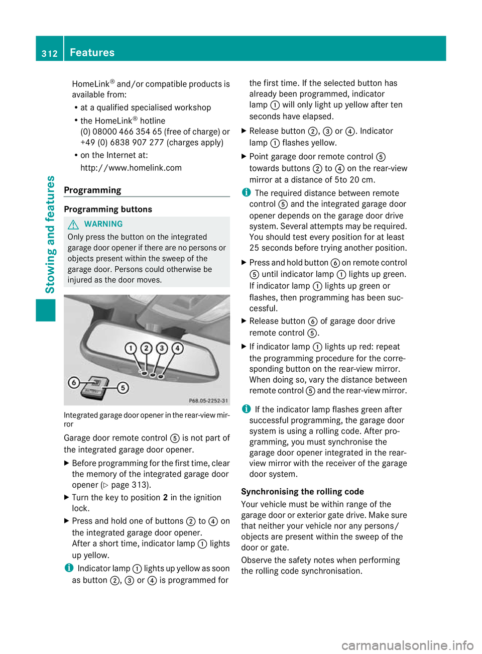
injured as the door moves. Integrated garage door opener in the rear-view mir-
ror
Garage door remote control
Ais not part of
the integrated garage door opener.
X Before programming for the first time, clear
the memory of the integrated garage door
opener (Y page 313).
X Turn the key to position 2in the ignition
lock.
X Press and hold one of buttons ;to? on
the integrated garage door opener.
After a short time, indicator lamp :lights
up yellow.
i Indicator lamp :lights up yellow as soon
as button ;,=or? is programmed for the first time. If the selected button has
already been programmed, indicator
lamp
:will only light up yellow after ten
seconds have elapsed.
X Release button ;,=or?. Indicator
lamp :flashes yellow.
X Point garage door remote control A
towards buttons ;to? on the rear-view
mirror at a distance of 5to 20 cm.
i The required distance between remote
control Aand the integrated garage door
opener depends on the garage door drive
system. Several attempt smay be required.
You should test every positio nfor at least
25 seconds before trying another position.
X Press and hold button Bon remote control
A until indicator lamp :lights up green.
If indicator lamp :lights up green or
flashes, then programming has been suc-
cessful.
X Release button Bof garage door drive
remote control A.
X If indicator lamp :lights up red: repeat
the programming procedure for the corre-
sponding button on the rear-view mirror.
When doing so, vary the distance between
remote control Aand the rear-view mirror.
i If the indicator lamp flashes green after
successful programming, the garage door
system is using a rolling code. After pro-
gramming, you must synchronise the
garage door opener integrated in the rear-
view mirror with the receiver of the garage
door system.
Synchronising the rolling code
Your vehicle must be within range of the
garage door or exterior gate drive. Make sure
that neither your vehicle nor any persons/
objects are present within the sweep of the
door or gate.
Observe the safety notes when performing
the rolling code synchronisation. 312
FeaturesStowing and features