2012 MERCEDES-BENZ B-CLASS tailgate
[x] Cancel search: tailgatePage 238 of 340

Useful information
i This Operator's Manual describes all
models and all standard and optional
equipment of your vehicle available at the
time of publication of the Operator's
Manual. Country-specific differences are
possible. Please note
that your vehicle may
not be equipped with all features
described. This also applies to safety-
related systems and functions.
i Read the information on qualified
specialist workshops: ( Y page 24).Loading guidelines
G
WARNING
If objects, luggage or loads are not secured or
not secured sufficiently, they could slip, tip
over or be
flung around and thereby hit vehicle
occupants. There is a risk of injury,
particularly in the event of sudden braking or
a sudden change in direction.
Always store objects so that they cannot be
flung around. Secure objects, luggage or
loads against slipping or tipping before the
journey. G
WARNING
Combustion engines emit poisonous exhaust
gases such as
carbon monoxide. If the tailgate
is open when the engine is running,
particularly if the vehicle is moving, exhaust
fumes could enter the passenger
compartment. There is a risk of poisoning.
Turn off the engine before opening the
tailgate. Never drive with the tailgate open.
The handling characteristics of a laden
vehicle are dependent on the distribution of
the load within the vehicle. For this reason,
you should observe the following notes when
transporting a load:
R Never exceed the maximum permissible
gross vehicle weight or the gross axle weight rating of the vehicle (including
occupants). The
values
are specified on the
vehicle identification plate on the B-pillar of
the driver's door.
R The cargo compartment is the preferred
place to carry objects.
R Position heavy loads as far forwards as
possible and as low down in the cargo
compartment as possible.
R The load must not protrude above the
upper edge of the seat backrests.
R Always place the load against the rear or
front seat backrests. Make sure that the
seat backrests are securely locked into
place.
R Always place the load behind unoccupied
seats if possible.
R Use the cargo tie down rings and the parcel
nets to transport loads and luggage.
R Use cargo tie-down rings and fastening
materials appropriate for the weight and
size of the load.
R Hook in the cargo net when loading.
R The maximum load capacity of the stowage
well under the cargo compartment floor is
55 lbs (25 kg).
R Secure the load with sufficiently strong and
wear-resistant tie-downs. pad sharp edges
for protection.
! Do not position the load on one part of the
folding cargo compartment floor only. The
maximum load capacity of the folding cargo
compartment floor is 220 lbs (100 kg).
Distribute the weight evenly to avoid
damaging the cargo compartment floor.
Place a solid board under the load if
necessary. Please note that the load on the
cargo compartment floor will be increased
when the load is lashed down. 236
Loading guidelines
Stowage and features
ProCarManuals.com
Page 248 of 340

Always close the cargo compartment floor
before a journey.
! The maximum load capacity of the
stowage well under
the cargo compartment
floor is 55 lbs (25 kg).
Opening/closing the cargo
compartment floor A bracket for TIREFIT, the vehicle tool kit, etc.
is located underneath the cargo
compartment floor.
X
To open: open the tailgate.
X Press down handle : on ribbing ;.
Handle : folds up.
X Swing the cargo compartment floor
upwards using handle : until it rests
against the cargo compartment cover. X
Fold out hook = on the underside of the
cargo compartment floor. X
Attach hook = to the cargo
compartment's upper seal ?.
X To close: detach hook = from seal ?.
X Fasten hook = to the bracket on the
underside of the
cargo compartment floor.
X Fold the trunk floor down.
X Press the trunk floor down until it engages.
Setting the height of the trunk floor The stowage well under the cargo
compartment floor can be increased or
decreased in size as necessary. To do this,
you can
lock
the floor at two different heights.
The upper catch gives a flat load surface when
the rear bench seat is folded forward. 246
Stowage areas
Stowage and features
ProCarManuals.com
Page 249 of 340

X
To raise: using handle :, lift up cargo
compartment floor ; in the direction of
arrow = and pull it upwards.
X Lower cargo compartment floor ; again.
To do
this,
push the trunk floor away so that
it engages in the guide on the upper level.
Cargo compartment floor ; engages in
the upper position.
i Carry out this step using both hands.
X To lower: raise cargo compartment
floor ; slightly
using
handle : and pull it
towards you.
X Lower cargo compartment floor ; again
slowly. Whilst doing so, press the trunk
floor into the lower level.
Cargo compartment floor ; engages in
the lower position. Roof carrier
Important safety notes G
WARNING
When you load the roof, the center of gravity
of the vehicle rises and the driving
characteristics change. If you exceed the
maximum roof load, the driving
characteristics, as well as steering and
braking, will be greatly impaired. There is a
risk of an accident.
Never exceed the maximum roof load and
adjust your driving style.
! Mercedes-Benz recommends that you
only use roof
carriers that have been tested
and approved for Mercedes-Benz vehicles.
This helps to prevent damage to the
vehicle.
Position the load on the roof rack in such a
way that the vehicle will not sustain
damage even when it is in motion.
Ensure that, depending on the vehicle's
equipment, you can raise the panorama
roof with power tilt/sliding panel fully and open the tailgate fully when the roof carrier
is installed.
The maximum roof load is 165 lbs((75 kg).
An incorrectly secured roof carrier or roof
load may
become detached from the vehicle.
You must therefore ensure that you observe
the roof carrier manufacturer's installation
instructions.
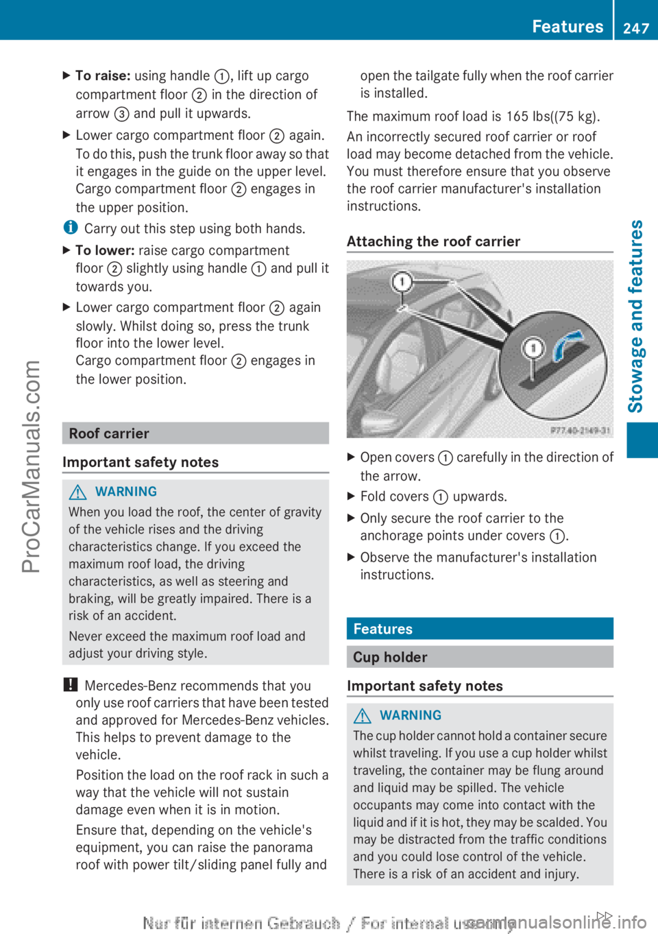
Attaching the roof carrier X
Open covers : carefully in
the direction of
the arrow.
X Fold covers : upwards.
X Only secure the roof carrier to the
anchorage points under covers :.
X Observe the manufacturer's installation
instructions. Features
Cup holder
Important safety notes G
WARNING
The cup holder cannot hold a container secure
whilst traveling. If
you use a cup holder whilst
traveling, the container may be flung around
and liquid may be spilled. The vehicle
occupants may come into contact with the
liquid and if it is hot, they may be scalded. You
may be distracted from the traffic conditions
and you could lose control of the vehicle.
There is a risk of an accident and injury. Features
247
Stowage and features
ZProCarManuals.com
Page 266 of 340

X
Push a round pen into opening
=(Y page 263) for approximately three
seconds.
The zone currently selected appears in
compass display ;(Y page 263).
X To select the zone: push
a round pen into
opening =(Y page 263) until the desired
zone is selected.
If, after a few seconds, the display in
compass display ;(Y page 263) changes
direction, the zone has been selected.
Calibrating the compass X
Make sure that there is sufficient space for
you to drive in a circle without impeding
traffic.
In order to calibrate the compass correctly,
do the following:
R calibrate the compass in the open and not
in the vicinity of steel structures or high-
voltage transmission lines.
R switch off electrical
consumers such as the
climate control, windshield wipers or rear
window defroster.
R close all doors and the tailgate.
X Switch on the ignition.
X Push a round pen into opening
=(Y page 263) for approximately six
seconds, until symbol C is shown in
compass display ;(Y page 263).
X Drive your vehicle in a full circle at
approximately 3 mph (5 km/h) to 6 mph
(10 km/h
).
When the calibration has successfully been
completed, the current direction is shown
in compass display ;(Y page 263).Floormat on the driver's side
G
WARNING
Objects in the driver's footwell can restrict the
pedal travel or obstruct a depressed pedal. The operating and road safety of the vehicle
is jeopardized. There is a risk of an accident.
Make sure that all objects in the vehicle are
stowed correctly, and that they cannot enter
the driver's footwell. Install the floormats
securely and as specified in order to ensure
sufficient clearance
for
the pedals. Do not use
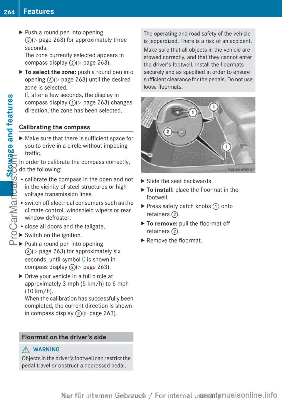
loose floormats. X
Slide the seat backwards.
X To install: place the floormat in the
footwell.
X Press safety catch knobs : onto
retainers ;.
X To remove: pull the floormat off
retainers ;.
X Remove the floormat.264
Features
Stowage and features
ProCarManuals.com
Page 282 of 340

Useful information
i This Operator's Manual describes all
models and all standard and optional
equipment of your vehicle available at the
time of publication of the Operator's
Manual. Country-specific differences are
possible. Please note
that your vehicle may
not be equipped with all features
described. This also applies to safety-
related systems and functions.
i Read the information on qualified
specialist workshops: ( Y page 24).Where will I find...?
First-aid kit
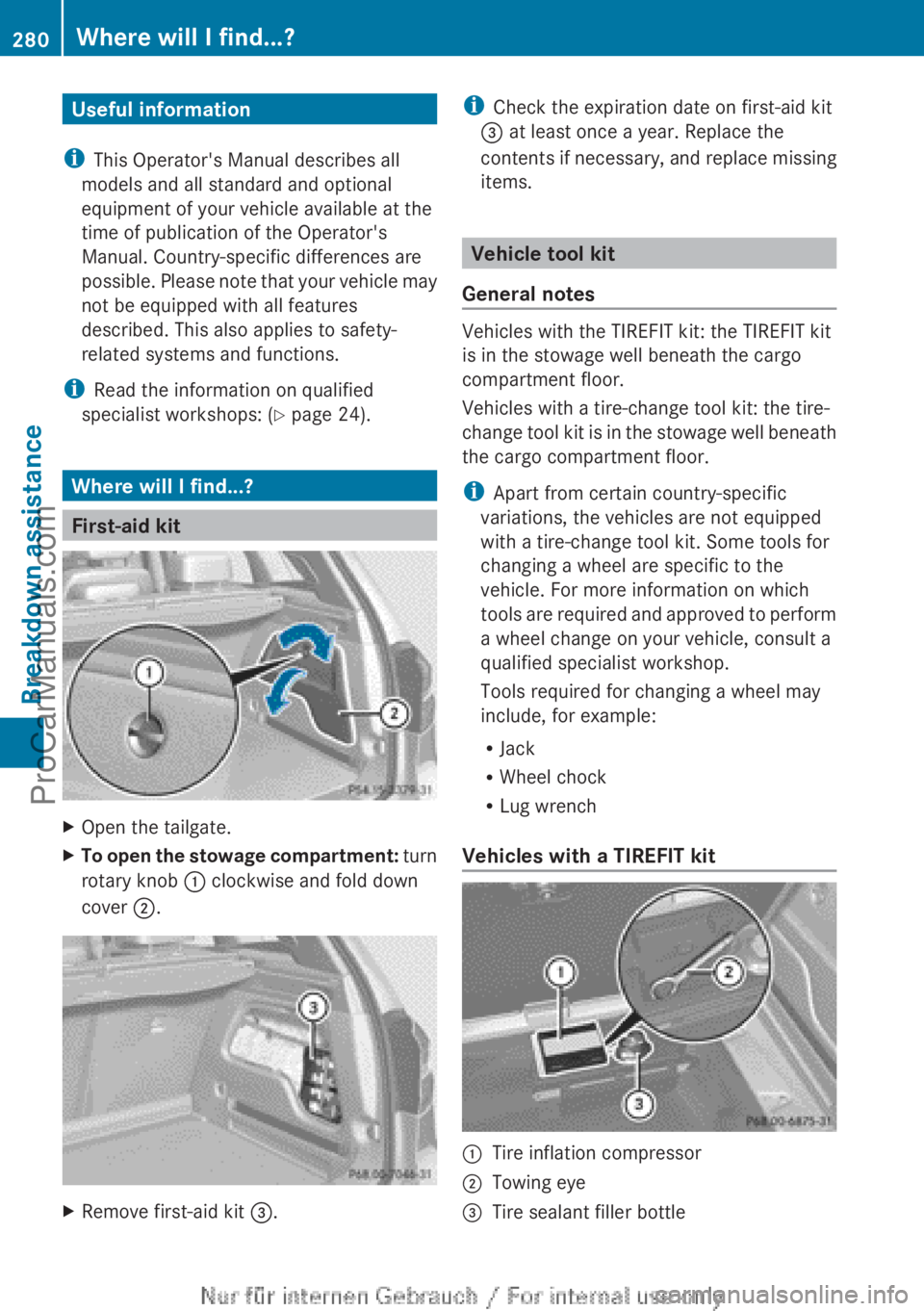
X
Open the tailgate.
X To open the stowage compartment: turn
rotary knob :
clockwise and fold down
cover ;. X
Remove first-aid kit =. i
Check the expiration date on first-aid kit
= at least once a year. Replace the
contents if necessary,
and replace missing
items. Vehicle tool kit
General notes Vehicles with the TIREFIT kit: the TIREFIT kit
is in the stowage well beneath the cargo
compartment floor.
Vehicles with a tire-change tool kit: the tire-
change
tool
kit
is in the stowage well beneath
the cargo compartment floor.
i Apart from certain country-specific
variations, the vehicles are not equipped
with a tire-change tool kit. Some tools for
changing a wheel are specific to the
vehicle. For more information on which
tools are required and approved to perform
a wheel change on your vehicle, consult a
qualified specialist workshop.
Tools required for changing a wheel may
include, for example:
R Jack
R Wheel chock
R Lug wrench
Vehicles with a TIREFIT kit :
Tire inflation compressor
; Towing eye
= Tire sealant filler bottle280
Where will I find...?
Breakdown assistance
ProCarManuals.com
Page 283 of 340

X
Open the tailgate.
X Lift the cargo compartment floor up
(Y page 246).
i Towing eye ; is located under tire
inflation compressor :.
Vehicles with a tire-change tool kit X
Open the tailgate.
X Lift the cargo compartment floor up
(Y page 246).
X Remove the tire-change tool kit.
The tire-change tool kit contains:
R Jack
R Lug wrench
R One pair of gloves
R Folding wheel chock Flat tire
Preparing the vehicle
Your vehicle may be equipped with:
R MOExtended tires (tires with run-flat
properties) ( Y page 281)
Vehicle preparation is not necessary on
vehicles with MOExtended tires.
R a TIREFIT kit (Y page 280)
Information on changing/mounting a wheel
(Y page 319).
X Stop the vehicle on solid, non-slippery and
level ground, as far away as possible from
traffic.
X Switch on the hazard warning lamps.
X Secure the vehicle against rolling away
(Y page 149).
X If possible, bring the front wheels into the
straight-ahead position.
X Switch off the engine.
X Remove the SmartKey from the ignition
lock. X
All occupants must get out of the vehicle.
Make sure that
they are not endangered as
they do so.
X Make sure that no one is near the danger
area while a wheel is being changed.
Anyone who is not directly assisting in the
wheel change should, for example, stand
behind the barrier.
X Get out of the vehicle. Pay attention to
traffic conditions when doing so.
X Close the driver's door.
i Vehicles equipped with
MOExtended tires
are not equipped with a TIREFIT kit at the
factory. It is therefore recommended that
you additionally equip your vehicle with a
TIREFIT kit if you mount tires that do not
feature run-flat properties, e.g. winter tires.
A TIREFIT kit can be obtained from a
qualified specialist workshop. MOExtended tires (tires with run-flat
properties)
General notes With MOExtended tires (tires with run flat
characteristics), you can continue to drive
your vehicle even if there is a total loss of
pressure in one or more tires. The affected
tire must
not
show any clearly visible damage.
You can recognize MOExtended tires by the
MOExtended marking which appears on the
sidewall of the tire. You will find this marking
next to the tire size designation, the load-
bearing capacity and the speed index
(Y page 313).
MOExtended tires may only be used in
conjunction with an active tire pressure loss
warning system.
If the pressure loss warning message
appears in the multifunction display:
R Observe the instructions in the display
messages ( Y page 219).
R Check the tire for damage.
R If driving on, observe the following notes. Flat tire
281
Breakdown assistance
ProCarManuals.com
Page 328 of 340

warning system when the defective wheel
has been replaced with a new wheel.
An emergency spare wheel may also be
mounted against the direction of rotation.
Observe the time
restriction on use as well as
the speed limitation specified on the
emergency spare wheel.
Replace the tires after six years at the latest,
regardless of wear. This also applies to the
emergency spare wheel. Removing the emergency spare wheel
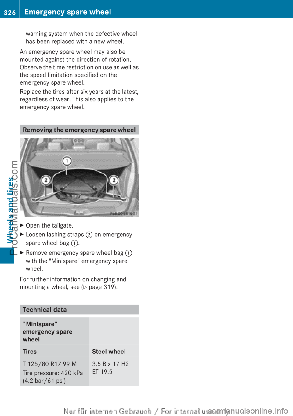
X
Open the tailgate.
X Loosen lashing straps ; on emergency
spare wheel bag :.
X Remove emergency spare wheel bag :
with the "Minispare" emergency spare
wheel.
For further information on changing and
mounting a wheel, see (
Y page 319). Technical data
"Minispare"
emergency spare
wheel
Tires Steel wheel
T 125/80 R17 99 M
Tire pressure: 420 kPa
(4.2 bar/61 psi) 3.5 B x 17 H2
ET 19.5326
Emergency spare wheel
Wheels and tires
ProCarManuals.com