Page 89 of 218
 88
SAFETY
STARTING
AND DRIVING
WARNING
LIGHTS AND
MESSAGES
IN AN
EMERGENCY
MAINTENANCE
AND CARE
TECHNICAL
SPECIFICA-
TIONS
INDEX
DASHBOARD
AND
CONTROLS
ACCESSORIES
PURCHASED BY
THE OWNER
If after buyi")
88
SAFETY
STARTING
AND DRIVING
WARNING
LIGHTS AND
MESSAGES
IN AN
EMERGENCY
MAINTENANCE
AND CARE
TECHNICAL
SPECIFICA-
TIONS
INDEX
DASHBOARD
AND
CONTROLS
ACCESSORIES
PURCHASED BY
THE OWNER
If after buying the car, you decide to
install electrical accessories that re-
quire a permanent electric supply
(alarm, satellite antitheft system, etc.)
or accessories that in any case burden
the electric supply, contact Lancia
Dealership, whose qualified person-
nel, besides suggesting the most suit-
able devices belonging to Lineacces-
sori Lancia, will also evaluate the
overall electric consumption, check-
ing whether the car’s electric system
is able to withstand the load required,
or whether it needs to be integrated
with a more powerful battery.
ELECTRICAL/ELECTRONIC
DEVICE INSTALLATION
Electric and electronic devices in-
stalled after buying the car by after-
market service must carry the follow-
ing label: MOBILE PHONE SETUP
(for versions/markets, where provided)
The mobile phone setup with CD or
CD MP3 sound system consists of:
❒a dual function aerial (sound sys-
tem + phone phone 900/1800
MHz) located on the roof;
❒connection cables to the dual func-
tion sound system and wiring with
10 pin connector.
The connector is located between the
steering column and the central unit.
The hands-free kit must be
purchased by the customer
because it must be compat-
ible with the customer’s
mobile phone. It is advisable to in-
stall the microphone near the front
ceiling light.
The maximum applicable
power to the aerial is 20W.
WARNING
For installing the mobile
phone and connecting to
system setup in the car, contact
Lancia Dealership to prevent any
trouble that could impair car
safety.
WARNING
Be very careful when fit-
ting non-standard addi-
tional spoilers, light alloy wheels
or wheel cups: they could reduce
brake ventilation and consequently
brake efficiency in the case of re-
peated, violent braking or on long
downhill roads. Make sure that
nothing obstructs the pedal stroke
(mats, etc.)
WARNING
Page 90 of 218
 89
SAFETY
STARTING
AND DRIVING
WARNING
LIGHTS AND
MESSAGES
IN AN
EMERGENCY
MAINTENANCE
AND CARE
TECHNICAL
SPECIFICA-
TIONS
INDEX
DASHBOARD
AND
CONTROLS
Fiat Auto S.p.A. authorises the in-
stallation o")
89
SAFETY
STARTING
AND DRIVING
WARNING
LIGHTS AND
MESSAGES
IN AN
EMERGENCY
MAINTENANCE
AND CARE
TECHNICAL
SPECIFICA-
TIONS
INDEX
DASHBOARD
AND
CONTROLS
Fiat Auto S.p.A. authorises the in-
stallation of transceiving devices pro-
vided that they are installed accord-
ing to rules of good engineering prac-
tice respecting the manufacturer’s in-
dications by a specialised centre.
IMPORTANT Traffic police may not
allow the car on the road in the event
of assembly of devices which imply
modifications to the features of the
car. This may also cause lapse of war-
ranty in relation to faults caused by
the change or either directly or indi-
rectly related to it.
Fiat Auto S.p.A. shall not be liable for
damage caused by the installation of
accessories either not supplied or rec-
ommended by Fiat Auto S.p.A.
and/or installed in compliance with
the provided instructions.“DUAL DRIVE”
ELECTRIC POWER
STEERING SYSTEM
The car is provided with an electric
power steering system which only
works with the key at MARand the
engine running. The system called
“Dual drive” allows to customise the
effort required to turn the steering
wheel according to driving conditions.
ON/OFF (CITY function)
Press fig. 118in the central part of
the dashboard to turn the function on
and off.
The message CITY appears on the
multifunctional display when the
function is on.
With the CITY function the effort on
the steering wheel is lighter, thus fa-
cilitating parking manoeuvres: this is
particularly useful when driving in
towns. TRANSCEIVERS AND MOBILE
PHONES
Radio transmitter equipment (vehicle
mobile phones, CB radios, amateur
radio etc.) shall not be used inside the
car unless a separate aerial is
mounted on the roof.
IMPORTANT The use of similar de-
vices inside the passenger compart-
ment (without separated aerial) pro-
duces radio-frequency electromag-
netic fields which, amplified by the
resonance effects inside the passenger
compartment, may cause electrical
systems equipping the car to mal-
function. This could compromise
safety in addition to constituting a po-
tential hazard for the passengers.
In addition, transmission and recep-
tion of these devices may be affected
by the shielding effect of the car body.
As concerns EC-approved mobile
phones (GSM, GPRS, UMTS), strictly
comply with the instructions for use
provided by the mobile phone’s man-
ufacturer.
Page 91 of 218
 90
SAFETY
STARTING
AND DRIVING
WARNING
LIGHTS AND
MESSAGES
IN AN
EMERGENCY
MAINTENANCE
AND CARE
TECHNICAL
SPECIFICA-
TIONS
INDEX
DASHBOARD
AND
CONTROLS
The car can be driven using the me-
chanical ste")
90
SAFETY
STARTING
AND DRIVING
WARNING
LIGHTS AND
MESSAGES
IN AN
EMERGENCY
MAINTENANCE
AND CARE
TECHNICAL
SPECIFICA-
TIONS
INDEX
DASHBOARD
AND
CONTROLS
The car can be driven using the me-
chanical steering in case of failure to
the electric power steering system.
Take the car to a Lancia Dealership
as soon as possible.
IMPORTANT The steering may be-
fore stiffer when parking requiring a
lot of steering. This is normal and
caused by the electric control motor
overheating system. No repairs are
needed. The power steering system
will start working properly again the
next time the car is used. PARKING SENSORS
(for versions/markets, where provided)
Parking sensors are located in the rear
bumper and their function is to in-
form the driver, through an intermit-
tent buzzer, about the presence of ob-
stacles behind the car.
ACTIVATION
The sensors are automatically acti-
vated when the reverse gear is en-
gaged. As the distance from the ob-
stacle behind the car decreases, the
acoustic alarm becomes more fre-
quent.
fig. 114L0D0419m
Under no circumstances
should aftermarket opera-
tions involving steering system or
steering column modifications (e.g.:
installation of anti-theft device) be
carried out that could badly affect
performance and safety. This also
causes the warranty to become null
and void and results in vehicle non-
compliance with type-approval re-
quirements.
WARNING
FAILURE INDICATIONS
Electric power steering failure is indi-
cated by the turning on of warning
light
gon the instrument panel to-
gether with the dedicated message on
the multifunctional display (where
provided), (see section “Warning
lights and messages”).
Before starting any main-
tenance operation, stop the
engine and remove the key from the
ignition switch to operate the steer-
ing lock, particularly when the car
is lifted off the ground. If this is
not possible (i.e. if the key must be
kept in the MAR position or the en-
gine must be kept running), remove
the main electric power steering
system fuse.
WARNING
Page 92 of 218
 91
SAFETY
STARTING
AND DRIVING
WARNING
LIGHTS AND
MESSAGES
IN AN
EMERGENCY
MAINTENANCE
AND CARE
TECHNICAL
SPECIFICA-
TIONS
INDEX
DASHBOARD
AND
CONTROLS
Detection distances
The central range of action")
91
SAFETY
STARTING
AND DRIVING
WARNING
LIGHTS AND
MESSAGES
IN AN
EMERGENCY
MAINTENANCE
AND CARE
TECHNICAL
SPECIFICA-
TIONS
INDEX
DASHBOARD
AND
CONTROLS
Detection distances
The central range of action varies ac-
cording to the version: the range is
equal to 140 cm and to 70 cm for
small sized obstacles (or round park-
ing posts). The side action range is 60
cm.
If several obstacles are detected by the
sensors, only the nearest one is con-
sidered.
FAILURE INDICATIONS
See the “Warning lights and mes-
sages” chapter.
OPERATION WITH TRAILER
The system is deactivated automati-
cally when the trailer electric cable
plug is fitted into the car tow hook
socket.
The sensors are automatically enabled
again when the trailer cable plug is re-
moved. BUZZER WARNINGS
When the reverse gear is engaged an
intermittent acoustic signal is auto-
matically activated.
The acoustic signal:
❒becomes louder as the reduction of
distance between the car and the
obstacle decreases;
❒becomes continuous when the dis-
tance between the car and the ob-
stacle is less that 30 cm and stops
immediately if the distance raises;
❒is constant if the distance is unvar-
ied; if this situation concerns the
side sensors, the buzzer will stop af-
ter about 3 seconds to avoid, for ex-
ample, warning indications in the
event of manoeuvres along walls.
fig. 115L0D0395m
GENERAL WARNINGS
❒When parking, take the utmost
care to obstacles that may be set
above or under the sensors.
❒Objects set close to the car, under
certain circumstances are not de-
tected and could therefore cause
damages to the car or be dam-
aged.
❒indications sent by the sensors can
be altered by dirt, snow or ice de-
posited on the sensors or by ultra-
sound systems (e.g.: truck pneu-
matic brakes or pneumatic ham-
mers) set nearby the car.
Page 93 of 218
 92
SAFETY
STARTING
AND DRIVING
WARNING
LIGHTS AND
MESSAGES
IN AN
EMERGENCY
MAINTENANCE
AND CARE
TECHNICAL
SPECIFICA-
TIONS
INDEX
DASHBOARD
AND
CONTROLS
REFUELLING
PETROL ENGINES
Use only unleaded petr")
92
SAFETY
STARTING
AND DRIVING
WARNING
LIGHTS AND
MESSAGES
IN AN
EMERGENCY
MAINTENANCE
AND CARE
TECHNICAL
SPECIFICA-
TIONS
INDEX
DASHBOARD
AND
CONTROLS
REFUELLING
PETROL ENGINES
Use only unleaded petrol.
To avoid mistakes, the diameter of the
fuel filler is too small to introduce the
beak of a leaded petrol pump. The
petrol octane rating (RON) must not
be lower than 95.
IMPORTANT An inefficient catalyst
leads to harmful exhaust emissions,
thus contributing to air pollution.
IMPORTANT Never use leaded petrol,
even in small amount or in an emer-
gency, as this would damage the cat-
alyst beyond repair.
MULTIJET ENGINES
Operation at low temperatures
If the outside temperature is very low,
the diesel thickens due to the forma-
tion of paraffin clots with consequent
defective operation of the fuel supply
system.In order to avoid these problems, dif-
ferent types of diesel are distributed
according to the season: summer type,
winter type and arctic type (cold/
mountain areas). If refuelling with
diesel fuel whose features are not suit-
able to the temperature of use, it is
advisable to mix TUTELA DIESEL
ART additive in the proportions
shown on the container with the fuel.
Pour the additive into the tank before
the fuel.
When using or parking the car for a
long time in the mountains or cold ar-
eas, it is advisable to refuel using lo-
cally available fuel.
In this case, it is also advisable to keep
the tank over 50% full.
FILLING THE TANK
To fill the tank completely, top-up
twice after the pump switches off.
Further top-ups could cause faults in
the fuel feeding system. It is vital that the sensors
are always clean in order
for the system to work
properly. Take great care
when cleaning the sensors not to
scratch or damage them; avoid us-
ing dry, rough or hard cloths. Clean
the sensors with clean water with
the addition of car shampoo if nec-
essary. In washing stations, clean
the sensors quickly, keeping the
steam jet/high pressure washing
nozzles at least 10 cm away from
the sensors.
The driver is always and
only responsible for park-
ing and other dangerous manoeu-
vres. Always make sure that there
are no people, animals or objects
in the way when carrying out these
manoeuvres. Parking sensors are
designed to assist drivers: in all
cases, you must always pay the ut-
most attention during potentially
dangerous manoeuvres, even when
these are carried out a low speed.
WARNING
Page 94 of 218
 93
SAFETY
STARTING
AND DRIVING
WARNING
LIGHTS AND
MESSAGES
IN AN
EMERGENCY
MAINTENANCE
AND CARE
TECHNICAL
SPECIFICA-
TIONS
INDEX
DASHBOARD
AND
CONTROLS
The fuel cap A-fig. 118is key-lock-
able and has")
93
SAFETY
STARTING
AND DRIVING
WARNING
LIGHTS AND
MESSAGES
IN AN
EMERGENCY
MAINTENANCE
AND CARE
TECHNICAL
SPECIFICA-
TIONS
INDEX
DASHBOARD
AND
CONTROLS
The fuel cap A-fig. 118is key-lock-
able and has a catch (for versions/
markets, where provided) to prevent
misplacing it Bthat fastens it to the
flapC; to gain access to it, open the
flap then use the ignition key to turn
counter-clocwise and remove the cap.
When refuelling, hook the cap to the
device on the inner flap, as illustrated.OPENING THE FUEL CAP
IN AN EMERGENCY
In case of emergency, full the cord
A-
fig. 119to open the fuel flap.
Remove the protection to reach the
cord. For diesel engines, use
diesel fuel for motor vehi-
cles compliant with EN590
European specifications
only. The use of other products or
mixtures may damage the engine
beyond repair and consequently
cause lapse of warranty in relation
to the damage caused. If you acci-
dentally introduce other types of fuel
in the tank, do not start the engine
and empty the tank. If the engine has
run also for a very short time, you
will need to have the entire fuel feed
system emptied in addition to the
tank.
FUEL TANK CAP
The fuel flap is opened by the door
locking system. Therefore, if the doors
are locked, press D-fig. 117to open
the fuel flap.
The cap C-fig, 116has a device Bse-
curing it to the flap Aso that is can-
not be misplaced. To open the cap C
turn it anticlockwise and extract.
fig. 116L0D0399m
fig. 119L0D0490mfig. 117L0D0420m
fig. 118L0D0500m
Page 95 of 218
 94
SAFETY
STARTING
AND DRIVING
WARNING
LIGHTS AND
MESSAGES
IN AN
EMERGENCY
MAINTENANCE
AND CARE
TECHNICAL
SPECIFICA-
TIONS
INDEX
DASHBOARD
AND
CONTROLS
late how much particulates has been
trapped by t")
94
SAFETY
STARTING
AND DRIVING
WARNING
LIGHTS AND
MESSAGES
IN AN
EMERGENCY
MAINTENANCE
AND CARE
TECHNICAL
SPECIFICA-
TIONS
INDEX
DASHBOARD
AND
CONTROLS
late how much particulates has been
trapped by the filter. Since this filter
physically traps particulate, it should
be regenerated (cleaned) at regular in-
tervals by burning carbon particles.
The regeneration procedure is con-
trolled automatically by the engine
management control unit according to
the filter conditions and vehicle use
conditions. The following phenomena
may occur during the regeneration:
limited increase of idle speed, activation
of electric fan, limited increase of
smoke, high temperatures at the ex-
haust. These are not faults; they do not
impair vehicle performance or damage
the environment. If the dedicated mes-
sage is displayed, refer to section
“Warning lights and messages”.PROTECTING THE
ENVIRONMENT
The devices for curtailing petrol engine
emissions are the following:
❒three-way catalytic converter;
❒Lambda sensor;
❒fuel evaporation system.
In addition, do not let the engine run,
even for a test, with one or more spark
plugs disconnected.
The devices for reducing diesel fuel en-
gine emissions are the following:
❒oxidising catalytic converter;
❒exhaust gas recirculation system
(E.G.R.);
❒diesel particulate filter (DPF)
DPF (DIESEL PARTICULATE
FILTER)
(for 1.3 Multijet 90 HP - 1.3 Multijet
95 HP versions)
The Diesel Particulate Filter is a me-
chanical filter, integral with the exhaust
system, that physically traps particu-
lates present in the exhaust gases of
Diesel engines. The diesel particular fil-
ter has been adopted to eliminate al-
most totally particulates in compliance
with current / future law regulations.
During normal use of the vehicle, the
engine control unit records a set of data
(e.g.: travel time, type of route, tem-
peratures, etc.) and it will then calcu- When refuelling, fasten the cap to the
device inside the flap as shown in the
diagram.
IMPORTANT The airtight sealing of
the tank may cause a slight vacuum.
A suction noise when you release the
cap is therefore entirely normal.
After refuelling, fasten the cap by
turning it clockwise until you hear it
click, then turn the key clockwise ad
remove the key from the flap.
Do not approach naked
flames or lit cigarettes to
the fuel filler: fire risk. Keep your
face away from the fuel filler to
prevent breathing in harmful
vapours.
WARNING
The catalytic converter de-
velops high temperature
during operation. Do not park on
grass, dry leaves, pine needles or
other flammable material: fire
risk.
WARNING
Page 96 of 218
95
STARTING
AND DRIVING
WARNING
LIGHTS AND
MESSAGES
IN AN
EMERGENCY
MAINTENANCE
AND CARE
TECHNICAL
SPECIFICA-
TIONS
INDEX
DASHBOARD
AND
CONTROLS
SAFETY
SAFETY
SEAT BELTS ..................................................... 96
PRETENSIONERS............................................. 99
CARRYING CHILDREN SAFELY ...................... 101
“UNIVERSAL ISOFIX”
CHILD RESTRAINT
ASSEMBLY SETUP.......................................... 105
FRONT AIRBAGS.............................................. 108
SIDE AIRBAG
(Side bags - Front Window bags)........................ 110
 1
1 2
2 3
3 4
4 5
5 6
6 7
7 8
8 9
9 10
10 11
11 12
12 13
13 14
14 15
15 16
16 17
17 18
18 19
19 20
20 21
21 22
22 23
23 24
24 25
25 26
26 27
27 28
28 29
29 30
30 31
31 32
32 33
33 34
34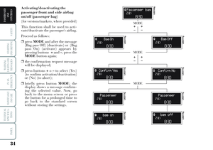 35
35 36
36 37
37 38
38 39
39 40
40 41
41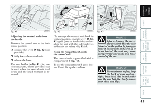 42
42 43
43 44
44 45
45 46
46 47
47 48
48 49
49 50
50 51
51 52
52 53
53 54
54 55
55 56
56 57
57 58
58 59
59 60
60 61
61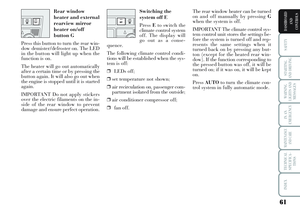 62
62 63
63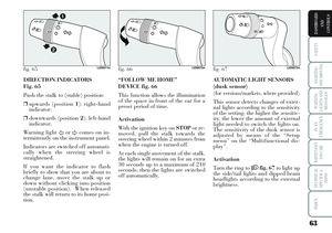 64
64 65
65 66
66 67
67 68
68 69
69 70
70 71
71 72
72 73
73 74
74 75
75 76
76 77
77 78
78 79
79 80
80 81
81 82
82 83
83 84
84 85
85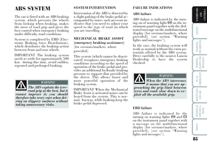 86
86 87
87 88
88 89
89 90
90 91
91 92
92 93
93 94
94 95
95 96
96 97
97 98
98 99
99 100
100 101
101 102
102 103
103 104
104 105
105 106
106 107
107 108
108 109
109 110
110 111
111 112
112 113
113 114
114 115
115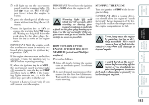 116
116 117
117 118
118 119
119 120
120 121
121 122
122 123
123 124
124 125
125 126
126 127
127 128
128 129
129 130
130 131
131 132
132 133
133 134
134 135
135 136
136 137
137 138
138 139
139 140
140 141
141 142
142 143
143 144
144 145
145 146
146 147
147 148
148 149
149 150
150 151
151 152
152 153
153 154
154 155
155 156
156 157
157 158
158 159
159 160
160 161
161 162
162 163
163 164
164 165
165 166
166 167
167 168
168 169
169 170
170 171
171 172
172 173
173 174
174 175
175 176
176 177
177 178
178 179
179 180
180 181
181 182
182 183
183 184
184 185
185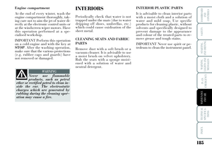 186
186 187
187 188
188 189
189 190
190 191
191 192
192 193
193 194
194 195
195 196
196 197
197 198
198 199
199 200
200 201
201 202
202 203
203 204
204 205
205 206
206 207
207 208
208 209
209 210
210 211
211 212
212 213
213 214
214 215
215 216
216 217
217 95
STARTING
AND DRIVING
WARNING
LIGHTS AND
MESSAGES
IN AN
EMERGENCY
MAINTENANCE
AND CARE
TECHNICAL
SPECIFICA-
TIONS
INDEX
DASHBOARD
AND
CONTROLS
SAFETY
SAFETY
SEAT BELTS ..............................")