Page 145 of 218
144
WARNING
LIGHTS AND
MESSAGES
MAINTENANCE
AND CARE
TECHNICAL
SPECIFICA-
TIONS
INDEX
DASHBOARD
AND
CONTROLS
SAFETY
STARTING
AND DRIVING
IN AN
EMERGENCY
To change a wheel proceed as follows:
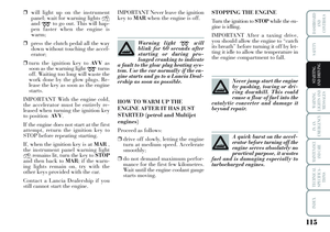
❒stop the car in a position so that it
is not a danger for on-coming traf-
fic and where you can replace the
wheel safely. The ground must be
flat and compact;
❒turn the engine off and pull up the
handbrake.
❒engage first gear or reverse;
❒lift the boot mat;
❒loosen the fastening device A-fig.
10;
❒take out the tool container Band
take it near to the wheel to be
changed;
❒take the space saver spare wheel
C;
L0D0161mfig. 10
Important notes:
❒the jack cannot be repaired: replace
with an original spare part if dam-
aged;
❒no tool other than its cranking de-
vice may be fitted on the jack.
Page 146 of 218

145
WARNING
LIGHTS AND
MESSAGES
MAINTENANCE
AND CARE
TECHNICAL
SPECIFICA-
TIONS
INDEX
DASHBOARD
AND
CONTROLS
SAFETY
STARTING
AND DRIVING
IN AN
EMERGENCY
fig. 11L0D0397m
fig. 12L0D0163m
❒for cars fitting alloy rims, remove
the hub cap using the screwdriver
provided levering in groove E-
fig. 11, as shown in the figure;
❒loosen the bolts of the wheel to be
replaced by about one turn with the
wrench provided E-fig. 12; if the
car is fitted with alloy rims, shake
the car to facilitate removing the
rim from the wheel hub;❒operate the device F- fig. 13to ex-
pand the jack, until the groove G
on the upper part of the jack is
correctly inserted on the lower
edgeHof the body at indication I
(at approximately 60 cm from the
front wheel centre or 80 cm from
the rear wheel centre);
❒warn anybody nearby that the car
is about to be lifted. They must
stay clear and not touch the car
until it is back on the ground;❒fit the handle L-fig. 13to operate
the jack and lift the car until the
wheel to be changed is several cen-
timetres off the ground;
❒for versions with wheel cap, remove
the wheel cap after loosening the
three fastening bolts and finally
loosen the fourth bolt and extract
the wheel;
❒for versions with snap fitted wheel
cup, remove the cup being careful
not to damage it;
❒make sure the contact surfaces be-
tween space saver spare wheel and
hub are clean so that the fastening
bolts will not come loose;
L0D0164mfig. 13
Page 147 of 218

146
WARNING
LIGHTS AND
MESSAGES
MAINTENANCE
AND CARE
TECHNICAL
SPECIFICA-
TIONS
INDEX
DASHBOARD
AND
CONTROLS
SAFETY
STARTING
AND DRIVING
IN AN
EMERGENCY
fig. 14L0D0165mfig. 15L0D0166m
❒fit the space saver spare wheel
making the holes M-fig. 14coin-
cide with the corresponding cen-
tring pins N;
❒using the wrench provided, tighten
the fastening bolts;
❒turn the jack handle to lower the
car and remove the jack;
❒use the wrench provided to fasten
the bolts completely in a criss-cross
fashion as shown in figure. REFITTING THE
STANDARD WHEEL
Following the procedure described
previously, raise the car and remove
the space saver spare wheel.
Versions with steel rims
Proceed as follows:
❒Make sure the contact surfaces be-
tween standard wheel and hub are
clean so that the fastening bolts
will not come loose.
❒Fit the standard wheel by inserting
the first bolt for two threads into
the hole closest to the inflation
valve.❒Fit the wheel cup making the
groove (on the cup) coincide with
the inflation valve and then insert
the other three bolts.
❒For models with snap-on wheel
cup, press the edge of the cup with
the palm of your hands against the
wheel (do not hammer).
❒Using the wrench provided,
tighten the fastening bolts.
❒Lower the car and remove the
jack.
❒using the wrench provided, fully
tighten the bolts in the sequence
shown previously in figure fig. 15.
IMPORTANT Incorrect assembly may
cause the cup to come off while trav-
elling.
Page 148 of 218

147
WARNING
LIGHTS AND
MESSAGES
MAINTENANCE
AND CARE
TECHNICAL
SPECIFICA-
TIONS
INDEX
DASHBOARD
AND
CONTROLS
SAFETY
STARTING
AND DRIVING
IN AN
EMERGENCY
Versions with alloy rims
❒Check that the hub contact sur-
faces are clean;
❒fit the normal wheel centring it on
the pins, lead in the fastening
screws and tighten them using the
wrench provided;
❒lower the car and remove the jack;
❒using the wrench provided, fully
tighten the bolts in the sequence
shown in fig. 15.
❒snap fit the wheel cup on the hub.When you have finished
❒stow the spare wheel in the space
provided in the boot;
❒fit the jack partially open in its
box forcing it lightly to prevent it
from vibrating when travelling;
❒put the tools back into their places
in the container;
❒arrange the container and tools in
the spare wheel and secure the fas-
tening device;
❒rearrange the preformed boot
cover correctly. WHEN NEEDING
TO CHANGE A
BULB
GENERAL INSTRUCTIONS
❒When a bulb is not working, check
that the corresponding fuse is in-
tact before replacing it: refer to the
“If a fuse blows” paragraph in this
chapter for fuse location.
❒before changing a bulb check the
contacts for oxidation;
❒burnt bulbs must be replaced by
others of the same type and power;
❒always check the height of the
headlight beam after changing a
bulb.
Halogen lamps must be
handled holding the metal-
lic part only. Touching the
transparent part of the bulb
with your fingers may reduce the in-
tensity of the emitted light and even
compromise duration of the lamp it-
self.
Page 149 of 218

148
WARNING
LIGHTS AND
MESSAGES
MAINTENANCE
AND CARE
TECHNICAL
SPECIFICA-
TIONS
INDEX
DASHBOARD
AND
CONTROLS
SAFETY
STARTING
AND DRIVING
IN AN
EMERGENCY
Modifications or repairs to
the fuel feed system that
are not carried out properly or do
not take the system’s technical
specifications into account can
cause malfunctions leading to the
risk of fire.
WARNING
Halogen bulbs contain
pressurised gas which, if
broken, may cause small frag-
ments of glass to be projected out-
wards.
WARNING
BULB TYPES fig. 16
Various types of bulbs are fitted to
your car:
A All glass bulb: clipped into place.
Pull to extract.
B Bayonet bulbs: to remove this type
of bulb from its holder, press the
bulb and turn it anticlockwise.
C Cylindrical bulbs: release from the
contacts to extract.
D-E Halogen bulbs: release the fas-
tening clip from the correspond-
ing seat to remove the lamp.
L0D0178mfig. 16
The taillights and the
third brake light fit LEDs.
Contact a Lancia Dealership in
case of faults.
WARNING
IMPORTANT When the weather is cold
or damp or after hard rain or after
washing, the area of headlamps or rear
lights, may steam up and/or form drops
of condensation on the inside. This is a
natural phenomenon due to the differ-
ence in temperature and humidity be-
tween the inside and the outside of the
glass which does not indicate a fault
and does not compromise the normal
operation of lighting devices. The mist
disappears quickly turning the lights
on, starting from the centre of the dif-
fuser, extending progressively towards
the edges.
Page 150 of 218
149
WARNING
LIGHTS AND
MESSAGES
MAINTENANCE
AND CARE
TECHNICAL
SPECIFICA-
TIONS
INDEX
DASHBOARD
AND
CONTROLS
SAFETY
STARTING
AND DRIVING
IN AN
EMERGENCY
Bulbs Figure ref. Type Power
Main beam headlightsEH1 55W
Dipped beam headlights EH1 55W
Front sidelights AW5W 5W
Front fog lights (for versions/markets, where provided)EH1 55W
Front direction indicators BPY21W 21W
Side direction indicators AWY5W 5W
Rear direction indicators BPY21W 21W
Reversing lights BP21W 21W
Rear fog lights BP21W 21W
Number plate lights CC5W 5W
Front ceiling light AW5W 10W
Rear ceiling lightAW5W 10W
Rear ceiling lights (with sunroof)AW5W 5W
Boot light AW5W 5W
Page 151 of 218
150
WARNING
LIGHTS AND
MESSAGES
MAINTENANCE
AND CARE
TECHNICAL
SPECIFICA-
TIONS
INDEX
DASHBOARD
AND
CONTROLS
SAFETY
STARTING
AND DRIVING
IN AN
EMERGENCY
REPLACING
EXTERIOR BULBS
For the type of bulb and power rat-
ing, see “When needing to change a
bulb”.
FRONT LIGHT CLUSTER
The front light clusters contain side
lights, dipped beam, main beam and
direction indicator bulbs.
Remove the protective caps to remove
the side lights, the dipped beam and
the main beam headlights.
The bulbs are arranged inside the
light cluster fig. 17as follows:
Adipped beam headlights
Bmain beam headlights and Side-
lights
Cdirection indicators
After replacing, refit the protective
caps and check that they are secured
well.IMPORTANT Remove the engine
compartment fusebox B-fig. 18to ac-
cess the left headlights cover (in di-
rection of travel) for replacement.
fig. 18L0D0125mfig. 17L0D0157m
Before replacing bulbs,
wait for the engine to cool
down: RISK OF BURNS!
WARNING
Page 152 of 218

151
WARNING
LIGHTS AND
MESSAGES
MAINTENANCE
AND CARE
TECHNICAL
SPECIFICA-
TIONS
INDEX
DASHBOARD
AND
CONTROLS
SAFETY
STARTING
AND DRIVING
IN AN
EMERGENCYDIPPED BEAM HEADLIGHTS
fig. 19
To replace the bulb, proceed as fol-
lows:
❒
remove the protective cap;
❒disconnect the electrical connector
A-fig. 19;
❒release the bulb holder catch B, take
out the bulb Cand replace it;
❒fit the new bulb, ensuring that the
outline of the metal part coincides
with the grooves on the curve of the
headlight. Then reconnect the elec-
trical connector B and refasten the
bulb holder catch A;
❒after replacing the bulb, put the pro-
tective cap back into position.
MAIN BEAM HEADLIGHTS
fig. 20
To replace the bulb, proceed as fol-
lows:
❒
remove the protective cap;
❒disconnect the electric connector
A-fig. 20;
❒release the bulb holder catches B,
take out the bulb Cand replace it;
❒fit the new bulb, ensuring that the
outline of the metal part coincides
with the grooves on the curve of the
headlight. Then reconnect the elec-
trical connector Band refasten the
bulb holder catches A;
❒after replacing the bulb, put the pro-
tective cap back into position.
fig. 20L0D0159mfig. 19L0D0158m