Page 305 of 385

303
Wheels and tyres Tyre code (example) Meaning
DOT BT RA TY5 1709 Tyre identification number (TIN
a)
, ma y be only on
interior wall of wheel) and date of manufacture: DOT The tyre complies with the legal require-
ments of
the US
Department of Trans-
port, responsible for tyre safety regula-
tions. BT Place of manufacture code.
RA Information about manufacturer and tyre
siz
e. TY5 Manufacturer's tyre specifications.
1709 Date of manufacture: Week 17 of 2009.
TWI This identifies the position of the Tread Wear In-
dicat
or
⇒ page 298. MAX LOAD 615 KG
(1356 LBS) US load rating, indicating maximum permitted
loa
d per ty
re. MAX INFLATION 350 KPA
(51 PSI) US limit, indicating maximum permitted tyre
pre
s
sure. SIDEWALL 1 PLY RAYON Information about tyre wall components:
1 la
y
er of rayon (artificial silk). TREAD 4 PLIES
1 RAY
ON + 2
STEEL +
1 NYLON Information about tread components:
In the ex
amp
le, there are 4 layers below the
tread: 1 layer of rayon (artificial silk), 2 layers of
steel reinforcement and 1 layer of nylon. Information for the end consumer concerning the comparative values of
the es
t
ablished base tyres (standardised test procedures) :TREADWEAR 280 Relative service life of the tyre, with respect to
spec
ific
US standard test. TRACTION AA Braking capacity of tyre on wet surface (AA, A, B
or C). Tyre code (example) Meaning
TEMPERATURE A Tyre temperature resistance at higher test
speed
s
(A, B or C). If there are different letters, they are specific codes of the tyre manufac-
tur
er or s
pecific national codes. a)
The letters TIN refer to the tyre serial number.
Ty r
es with directional tread pattern
Tyres with directional tread pattern have been designed to operate best
when rotating in only one direction. An arrow on the tyre sidewall indicates
the direction of rotation on tyres with directional tread. Always observe the
direction of rotation indicated when mounting the wheel. This guarantees
optimum grip and helps to avoid aquaplaning, excessive noise and wear.
Tyre load rating
The load rating code indicates the maximum load in kilogrammes each
wheel can carry (load capacity).
615 kg (1356 pounds)
650 kg (1433 pounds)
690 kg (1521 pounds)
730 kg (1609 pounds)
775 kg (1709 pounds)
Speed rating
The speed rating indicates the maximum speed permitted for the tyres.
max. 150 km/h (93 mph)
max. 160 km/h (99 mph)
max. 170 km/h (106 mph)
max. 180 km/h (112 mph)
max. 190 km/h (118 mph)
max. 200 km/h (124 mph)
91
93
95
97
99
P
Q
R
S
T
U
Safety First Operating instructions Practical tips Technical Data
Page 306 of 385

304
Wheels and tyres
max. 210 km/h (130 mph)
max. 240 km/h (149 mph)
m ax. 240 km/h (149 mph)
m
ax. 270 km/h (168 mph)
max. 300 km/h (186 mph)
Some manufacturers use the letters “ZR” for tyres with a maximum author-
ised speed above 240 km/h (149 miles).
Wheel trims*
Introduction Additional information and warnings:
●
Caring for and cleaning the vehicle exterior ⇒ page 242
● Ch
ange wheel ⇒ page 305
● V
ehicle tools ⇒ page 320 WARNING
If the wheel trims are not appropriate or not fitted correctly, they could
cau se m
ajor accidents or damage.
● Incorrectly mounted wheel trims may come off while driving and en-
dang
er other road users.
● Damaged trims must never be mounted on the wheels.
● Always ensure that the brake ventilation and cooling is not cut off or
block
ed. This is also valid if hubcaps are fitted later. If there is not
enough air, you may require significantly longer braking distances. H
V
Z
W
Y
CAUTION
Remove and remount wheel trims taking care to avoid damage to the vehi-
cl e.
F
ull hubcaps* Fig. 179 Removing the
fu
l
l hubcap.
Removing the full hubcap
● Take the wheel brace and the wire hook from the vehicle tool kit
⇒ pag e 320.
● Hook
the wire through one of the grooves on the hubcap.
● Insert the wheel brace onto the wire hook ⇒ fig. 179 and pul
l the hub
cap in the direction shown by the arrow.
Fitting hubcaps
Before mounting the full hubcap, the anti-theft wheel lock must be threaded
into position ⇒ fig. 182 2 or
3 . Otherwise it will not be possible to mount
the fu l
l hubcap.
Page 307 of 385

305
Wheels and tyres
Press the hubcap against the wheel so that the space for the valve fits over
the tyr e
valve ⇒ fig. 182 1 . Make sure that the hubcap is correctly fitted all
the wa y
around the wheel.
Wheel bolt caps Fig. 180 Removing the
wheel bo
lt
caps
● Take the wire hook from the vehicle tool kit ⇒ page 320.
● In
sert the wire hook in the cap through the opening ⇒ fig. 180 and pul
l
outwards in the direction of the arrow.
The caps protect the wheel bolts and should be remounted after changing
the tyre.
The anti-theft wheel locking bolt has a special cap. This cap only fits on an-
ti-theft locking bolts and is not for use with standard wheel bolts. Changing a wheel*
Introduction The tyres mounted on the vehicle are anti-puncture. The wheels should only
be ch
an
ged when switching from summer to winter tyres or vice-versa. See
⇒ page 299
You should only change the wheels yourself if the vehicle is parked in a safe
place, you are familiar with the procedure and you have all the necessary
tools! Otherwise, you should seek professional assistance.
Additional information and warnings:
● Vehicle key set ⇒ pag
e 71
● Wheels and tyres ⇒ pag
e 293
● Wheel trims ⇒ pag
e 304
● Vehicle tools ⇒ pag
e 320 WARNING
Changing a wheel can be dangerous, especially on the hard shoulder.
Ple a
se observe the following rules to minimise the risk of injury:
● Stop the vehicle safely as soon as possible. Park your vehicle as safe
dist
ance from surrounding traffic to change a wheel.
● When changing a wheel, keep all passengers and particularly chil-
dren a saf
e distance away from the work area.
● Turn on the hazard warning lights to warn other road users.
● Ensure the ground on which you park is flat and solid. If necessary,
suppor
t the jack on a wide solid base.
● If you are changing a wheel yourself, you should be familiar with the
required pr
ocedure. Otherwise, you should seek professional assistance. Safety First Operating instructions Practical tips Technical Data
Page 308 of 385

306
Wheels and tyres WARNING (Continued)
● Only use suitable tools that are not damaged when changing a wheel.
● A
lw
ays stop the engine, turn on the electronic parking brake and
plac
e the gear selector lever in position P, for an automatic gearbox, or
engage a gear for a manual gearbox to reduce the risk of the vehicle mov-
ing accidentally.
● Have the tightening torque of the wheel bolts checked as soon as
poss
ible with a reliable torque wrench.
Preparations for changing a wheel Check list
Bef
or
e changing a wheel, complete the following operations in the order
given ⇒ :
Park the
vehicle on an even and solid surface.
Connect the electronic parking brake ⇒ page 183.
Automatic gearbox: Move selector lever to position P ⇒ page 174.
Stop the engine and remove the key from the ignition ⇒ page 170.
Manual gearbox: Select a gear ⇒ page 174.
Have all vehicle occupants get out of the vehicle and wait in a safe
place (for example, behind the safety barrier).
Block the opposite wheel with wedges or a similar object.
When towing a trailer: unhook the trailer from the towing vehicle and
park it correctly.
If the luggage compartment is full: take the baggage out of the vehicle. Take the vehicle tool kit out of the luggage compartment.
Remove the wheel trims ⇒ page 304.
1.
2.
3.
4.
5.
6.
7.
8.
9.
10.
11. WARNING
Failure to follow the checklist prepared for your own safety could lead to
acc ident
s and severe injuries.
● Always complete the operations given in the checklist and observe
the genera
l rules of safety.
Page 309 of 385

307
Wheels and tyres
Wheel bolts Fig. 181 Changing the
wheel: Sl
ac
ken the wheel
bolts. Fig. 182 Changing the
wheel: T
y
re valve 1 and
pos ition of
anti-theft
wheel locking bolt 2 or
3 .
Only use the tool supplied with the vehicle to loosen the wheel bolts.
Loo sen the wheel
bolts only about one turn before raising the vehicle with
the jack. If the wheel bolt is very tight, you may be able to loosen it by pushing down
on the end of the wheel br
ace carefully with your foot. Hold on to the car for
support and take care not to slip.
Loosening wheel bolts
● Fit the wheel brace as far as it will go over the wheel bolt ⇒ fig. 181.
● Hold the wheel brace at the end and rotate the bolt approximately one
turn antic
lockwise ⇒ .
Loo senin
g anti-theft wheel bolts
For wheels with full hubcap, the anti-theft wheel lock must be threaded into
position ⇒ fig. 182 2 or
3 before mounting the hubcap. Otherwise it will
not be po s
sible to mount the full hubcap.
● Take the adapter for anti-theft wheel bolts out of the vehicle tool kit.
● Insert the adapter onto the wheel bolt.
● Fit the wheel brace onto the adapter as far as possible.
● Hold the wheel brace at the end and rotate the bolt approximately one
turn antic
lockwise ⇒ .
Import ant
information about wheel bolts
The wheel rims and bolts have been designed to be fitted to factory op-
tions. If different rims are fitted, the correct wheel bolts with the right length
and correctly shaped bolt heads must be used. This ensures that wheels are
fitted securely and that the brake system functions correctly.
In some circumstances, wheel bolts from the same model vehicle should
not be used.
Wheel bolt tightening torque
The prescribed tightening torque for wheel bolts for steel and alloy wheels
is 140 Nm. Have the tightening torque of the wheel bolts checked as soon
as possible with a reliable torque wrench.
If wheel bolts are rusty and it is difficult to tighten them, the threads should
be replaced and cleaned before checking the torque. Safety First Operating instructions Practical tips Technical Data
Page 310 of 385

308
Wheels and tyres
Never grease or lubricate wheel bolts or the wheel hub threads. Although
they h av
e been tightened to the prescribed torque, they could come loose
while driving. WARNING
If the wheel bolts are not fitted correctly they could be released while
drivin g l
eading to loss of vehicle control and serious damage.
● Only use wheel bolts which correspond to the wheel rims in question.
● Never use different wheel bolts.
● The bolts and threads should be clean, free of oil and grease and easy
to thre
ad. WARNING (Continued)
● To loosen and tighten the wheel bolts, always use the wheel brace
s up
plied with the vehicle.
● Loosen the wheel bolts only about one turn before raising the vehicle
with the jac
k.
● Never grease or lubricate wheel bolts or the wheel hub threads. Al-
though they hav
e been tightened to the prescribed torque, they could
come loose while driving.
● Never loosen the bolted joints of wheel rims with bolted ring trims.
● If the wheel bolts are not tightened to the correct torque, they may
come loose whi
le driving, and the bolts and rims may come out. If the
tightening torque is too high, the wheel bolts and threads can be dam-
aged.
Page 311 of 385
309
Wheels and tyres
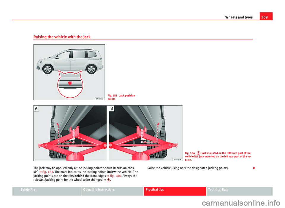
Raising the vehicle with the jack Fig. 183 Jack position
points
Fig. 184
A : jack mounted on the left front part of the
vehic l
e B : jack mounted on the left rear part of the ve-
hicl e.
The j
ack may be applied only at the jacking points shown (marks on chas-
sis)
⇒ fig. 183. The mark indicates the jacking points below the vehicle. The
jacking points are on the ribs behind the front edges ⇒ fig. 184. Always the
relevant jacking point for the wheel to be changed ⇒ .
Raise the vehicle using only the designated jacking points.
Safety First Operating instructions Practical tips Technical Data
Page 312 of 385

310
Wheels and tyres
Check list
For y
our own safety and that of other passengers, the following points
should be observed in the order given ⇒ :
Select a s
uitable flat and firm surface for raising the vehicle.
Switch off the engine, engage a gear (manual gearbox) or place the se-
lector lever in position P ⇒ page 174 and turn on the electronic parking
brake ⇒ page 183.
When towing a trailer: unhook the trailer from the towing vehicle and
park it correctly.
Loosen the wheel bolts on the wheel to be changed ⇒ page 307.
Look below the vehicle for the jacking point ⇒ fig. 183 closest to the
tyre which has to be changed.
Raise the jack with the handle until it can be inserted below the jacking
point.
Ensure that the foot of the jack is firmly on the ground and that it is
placed immediately below the lifting point on the vehicle ⇒ fig. 184.
Straighten the jack and continue raising it using the handle until the
claw holds the vertical reinforcement beneath the vehicle ⇒ fig. 184.
Raise the vehicle until the wheel is clear of the ground. WARNING
If the vehicle is not correctly raised, it could fall off the jack causing seri-
ous injur
y. Please observe the following rules to minimise the risk of in-
jury:
● You should only use a jack approved by SEAT for your vehicle. Other
jack
s, even those approved for other SEAT models, might slip out of
place.
● The ground should be firm and flat. If the ground is sloped or soft
then the vehic
le could slip and fall off the jack. If necessary, support the
jack on a wide solid base. 1.
2.
3.
4.
5.
6.
7.
8.
9. WARNING (Continued)
● If the ground is slippery (for example, on tiles), place a non-slip sur-
f ac
e (for example a floor mat) beneath the jack to avoid slipping.
● Only fit the jack at the prescribed jacking points. The claw of the jack
should grip the r
einforcement nerve on the underbody ⇒ fig. 184.
● You should never have any limbs beneath a raised vehicle which is
only s
upported by a jack.
● If you have to work underneath the vehicle, you must use suitable
stand
s additionally to support the vehicle, there is a risk of accident!.
● Never raise the vehicle if it is tilting to one side or the engine is run-
ning.
● Never s
tart the engine when the vehicle is raised. The vehicle may
come loose fr
om the jack due to the engine vibrations. WARNING
Failure to follow the checklist prepared for your own safety could lead to
acc ident
s and severe injuries.
● Always complete the operations given in the checklist and observe
the genera
l rules of safety.