2011 RENAULT SCENIC fuel type
[x] Cancel search: fuel typePage 11 of 365

13B-11
MR-372-J84-13B200$108.mif
V13
13B
DIESEL INJECTION
Fault finding – System operation
System outline
The high pressure injection system is designed to deliver a precise quantity of diesel fuel to the engine at a set
moment.
It is fitted with a 112-track BOSCH EDC16 C3 type computer.
The system comprises:
– a priming bulb on the low pressure circuit,
– a diesel filter,
– a high pressure pump with a built-in low pressure pump (transfer pump),
– a high pressure regulator mounted on the pump,
– an injector rail,
– a diesel fuel pressure sensor built into the rail,
– four solenoid injectors,
– a coolant temperature sensor,
– a cylinder reference sensor,
– an engine speed sensor,
– a turbocharger pressure sensor,
– an accelerator pedal potentiometer,
– an EGR solenoid valve,
– an atmospheric pressure sensor integrated into the injection computer,
– an air flowmeter with an air temperature sensor,
– a turbocharging pressure limitation solenoid valve,
– a motorised damper valve,
– a particle filter,
– a particle filter differential pressure sensor,
– a particle filter upstream temperature sensor,
– a particle filter downstream temperature sensor,
– a temperature sensor upstream of the turbine,
– four thermoplungers
The common rail direct high pressure injection system works sequentially (based on the petrol engine multipoint
injection).
This injection system reduces operating noise, reduces the volume of pollutant gases and particles and produces
high engine torque at low engine speeds thanks to a pre-injection procedure.
The high pressure pump generates the high pressure and transmits it to the injector rail. The actuator located on the
pump controls the quantity of diesel fuel supplied, according to the requirement determined by the computer. The rail
supplies each injector through a steel pipe.
MR-372-J84-13B200$108.mif
EDC16
Program No: C1
Vdiag No: 18, 1C, 20,
50, 58, 5C
Page 12 of 365

13B-12
MR-372-J84-13B200$108.mif
V13
DIESEL INJECTION
Fault finding – System operation
EDC16
Program No: C1
Vdiag No: 18, 1C, 20,
50, 58, 5C
13B
a) The computer:
Determines the value of injection pressure necessary for the engine to operate correctly and then controls the
pressure regulator.
Checks that the pressure value is correct by analysing the value transmitted by the pressure sensor located on the
rail.
It determines the injection timing required to deliver the right quantity of diesel fuel and the moment when injection
should start. Controls each injector electrically and individually after determining these two values.
The flow injected into the engine is determined by:
– the duration of injector control,
– the rail pressure (regulated by the computer),
– the injector opening and closing speed,
– the needle stroke (determined by a constant for the type of injector),
– the nominal hydraulic flow of the injector (specific to each injector).
The computer manages:
– idling regulation,
– exhaust gas flow reinjection to the inlet (EGR),
– fuel supply check (advance, flow and rail pressure),
– the fan assembly control,
– the air conditioning (cold loop function),
– the cruise control/speed limiter function,
– pre-post heating control,
– indicator lights control via the multiplex network,
– the operation of the catalysed particle filter.
The high pressure pump is supplied at low pressure by an integrated low pressure pump (transfer pump).
It supplies the rail, the pressure of which is controlled by the fuel flow actuator (MPROP) for charging, and for
discharging by the injector valves. This compensates for pressure drops. The flow actuator allows the high pressure
pump to supply the exact quantity of diesel fuel required to maintain the pressure in the rail. This component
minimises the heat generated and improves engine output.
In order to discharge the rail using the injector valves, the valves are controlled by brief electrical pulses which are:
– short enough not to open the injector (passing through the feedback circuit from the injectors),
– long enough to open the valves and discharge the rail.
Page 328 of 365

13B-328
MR-372-J84-13B200$828.mif
V13
EDC16
Program No.: C1
Vdiag no.: 18, 1C, 20,
50, 58, 5CDIESEL INJECTION
Fault finding – Fault Finding Chart13B
ALP 8 Oil leaks from the turbocharger
NOTESBefore dealing with this customer complaint, check that there are no faults, and
the conformity (or otherwise) of the parameters and statuses using the
diagnostic tool.
If the customer complaint is not eliminated, perform the following checks.
Check the area around the turbocharger
Note:
An oil leak does not correspond always to a turbocharger fault, the oil leak can arise from the area around the
turbocharger.
According to the vehicle type, maximum visual access will either be from above or from below.
1- Do not start the engine.
Check the area around the turbocharger and identify the origin of the leaks.
Clean the oil traces on the turbocharger.
2- start the engine and let it warm up for several minutes.
IMPORTANT
If the air filter was removed previously, refit it before starting the engine (risks foreign matter entering the air inlet
circuit).
Accelerate with no load several times, progressively increasing the duration before releasing the accelerator
pedal.
Visually inspect the exterior condition of the fuel supply pipes and the turbocharger oil return and the area around
it.
Identify the origin of the leaks.
Is an oil leak present at the air compressor inlet or outlet?
YES NO
Check the air compressor inlet or outlet
Check for a loose interface (inlet or outlet) that is the cause of
the air leak.
Note:
it is normal to find traces of oil inside the pipes at the
turbocharger inlet or outlet as the air passing into the
compressor is laden with oil from the engine rebreathing circuit.
Is the suspected interface properly tightened?
YES
Replace the pipe concerned (see MR 364 (Mégane II), 370 (Scénic II) or 395 (Laguna II), Mechanical, 12B,
Turbocharging).
NOTighten the interface or the
concerned pipe.
End of procedure.
AFTER REPAIRCarry out a road test followed by a complete check with the diagnostic tool.
EDC16_V50_ALP8/EDC16_V58_ALP8/EDC16_V5C_ALP8/EDC16_V18_ALP8/EDC16_V1C_ALP8/EDC16_V20_ALP8
Page 341 of 365

13B-341
MR-372-J84-13B200$900.mif
V13
EDC16
Program No.: C1
Vdiag no.: 18, 1C, 20,
50, 58, 5CDIESEL INJECTION
Fault finding – Tests13B
TEST 2 Turbocharger air chain
Check for the air filter
Check the replacement frequency for the air filter in the Maintenance Booklet.
Compare the part numbers of the air filter fitted to the vehicle and that of the air filter recommended by the
manufacturer.
Check the air filter direction of fitting.
Is the air filter fitted to the vehicle correct?
YES NO
Check the condition of the air filter
Visually inspect the condition of the filter section of
the air filter.
Is either the air filter or its seal damaged?
Is the air filter clogged (does it contain a lot of
impurities)?
NO
Low pressure circuit check
Note:
According to the vehicle type, maximum visual
access will either be from above or from below.
Visually inspect the condition of the following
components:
– fresh air inlet scoop on the front end panel of the
vehicle,
– air filter air inlet pipe,
– filter air pipe up to the compressor inlet,
– air flowmeter mountings.
Is one of these components incorrect
(disconnected, cut, bent, pierced or kinked
pipes)?
NO
YESReplace the air filter (see MR 364
(Mégane II), 370 (Scénic II) or 395
(Laguna II), Mechanical, 12A, Fuel
mixture, Air filter, Removal –
Refitting).
YESReplace the defective parts (see MR 364
(Mégane II), 370 (Scénic II) or 395
(Laguna II), Mechanical, 12B,
Turbocharging).
EDC16_V50_TEST2/EDC16_V58_TEST2/EDC16_V5C_TEST2/EDC16_V18_TEST2/EDC16_V1C_TEST2/EDC16_V20_TEST2
Page 358 of 365

13B-358
MR-372-J84-13B200$936.mif
V13
DIESEL INJECTION
Fault finding – Tests
EDC16
Program No: C1
Vdiag No: 18, 1C, 20,
50, 58, 5C
13B
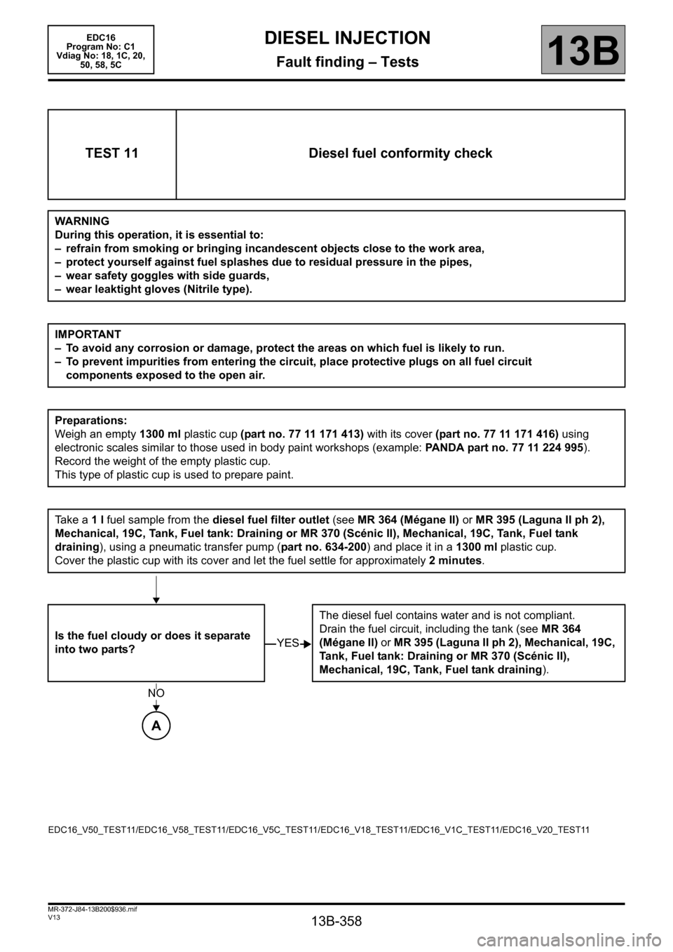
TEST 11 Diesel fuel conformity check
WARNING
During this operation, it is essential to:
– refrain from smoking or bringing incandescent objects close to the work area,
– protect yourself against fuel splashes due to residual pressure in the pipes,
– wear safety goggles with side guards,
– wear leaktight gloves (Nitrile type).
IMPORTANT
– To avoid any corrosion or damage, protect the areas on which fuel is likely to run.
– To prevent impurities from entering the circuit, place protective plugs on all fuel circuit
components exposed to the open air.
Preparations:
Weigh an empty 1300 ml plastic cup (part no. 77 11 171 413) with its cover (part no. 77 11 171 416) using
electronic scales similar to those used in body paint workshops (example: PANDA part no. 77 11 224 995).
Record the weight of the empty plastic cup.
This type of plastic cup is used to prepare paint.
Ta k e a 1 l fuel sample from the diesel fuel filter outlet (see MR 364 (Mégane II) or MR 395 (Laguna II ph 2),
Mechanical, 19C, Tank, Fuel tank: Draining or MR 370 (Scénic II), Mechanical, 19C, Tank, Fuel tank
draining), using a pneumatic transfer pump (part no. 634-200) and place it in a 1300 ml plastic cup.
Cover the plastic cup with its cover and let the fuel settle for approximately 2 minutes.
Is the fuel cloudy or does it separate
into two parts?The diesel fuel contains water and is not compliant.
Drain the fuel circuit, including the tank (see MR 364
(Mégane II) or MR 395 (Laguna II ph 2), Mechanical, 19C,
Tank, Fuel tank: Draining or MR 370 (Scénic II),
Mechanical, 19C, Tank, Fuel tank draining).
YES
NO
A
EDC16_V50_TEST11/EDC16_V58_TEST11/EDC16_V5C_TEST11/EDC16_V18_TEST11/EDC16_V1C_TEST11/EDC16_V20_TEST11
Page 365 of 365

13B-365
MR-372-J84-13B200$972.mif
V13
13B
DIESEL INJECTION
Fault finding – Glossary
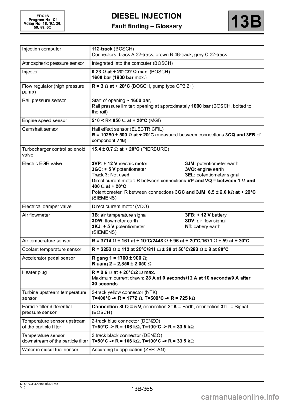
Injection computer112-track (BOSCH)
Connectors: black A 32-track, brown B 48-track, grey C 32-track
Atmospheric pressure sensor Integrated into the computer (BOSCH)
Injector0.23 Ω at + 20°C/2 Ω max. (BOSCH)
1600 bar (1800 bar max.)
Flow regulator (high pressure
pump)R = 3 Ω at + 20°C (BOSCH, pump type CP3.2+)
Rail pressure sensor Start of opening ~ 1600 bar,
Rail pressure limiter: opening at approximately 1800 bar (BOSCH, bolted to
the rail)
Engine speed sensor510 < R< 850 Ω at + 20°C (MGI)
Camshaft sensor Hall effect sensor (ELECTRICFIL)
R = 10250 ± 500 Ω at + 20°C (measured between connections 3CQ and 3FB of
component 746)
Turbocharger control solenoid
valve15.4 ± 0.7 Ω at + 20°C (PIERBURG)
Electric EGR valve3VP: + 12 V electric motor 3JM: potentiometer earth
3GC: + 5 V potentiometer 3VQ: engine earth
Track 3: Not used 3EL: potentiometer signal
Direct current motor: R between connections VP and VQ = between 1 Ω and
400 Ω at + 20°C
Potentiometer: R between connections 3GC and 3JM: 6.5 ± 2.6 kΩ at + 20°C
(SIEMENS)
Electrical damper valve Direct current motor (VDO)
Air flowmeter3B: air temperature signal 3FB: + 12 V battery
3DW: flowmeter earth 3DV: air flow signal
3KJ: + 5 V potentiometer NT: battery earth
(SIEMENS)
Air temperature sensorR = 3714
Ω ± 161 at + 10°C/2448 Ω ± 96 at + 20°C/1671 Ω ± 59 at + 30°C
Coolant temperature sensorR = 2252 Ω ± 112 at 25°C/811 Ω ± 39 at 50°C/283 Ω ± 8 at 80°C
Accelerator pedal sensorR gang 1 = 1700 ± 900 Ω;
R gang 2 = 2,850 ± 2,050Ω
Heater plugR = 0.6 Ω at + 20°C/2 Ω max.
Maximum current drawn: 28 A at 0 seconds/12 A at 10 seconds/9 A after
30 seconds
Turbine upstream temperature
sensor2-track yellow connector (NTK)
T=400°C -> R = 1772 Ω, T=500°C -> R = 725 kΩ
Particle filter differential
pressure sensorConnection 3LQ = 5 V, connection 3TK = Earth, connection 3TL = Signal
(BOSCH)
Temperature sensor upstream
of the particle filter2-track blue connector (DENZO)
T=50°C -> R = 106 kΩ, T=100°C -> R = 33.5 kΩ
Temperature sensor
downstream of the particle filter2 track black connector (DENZO)
T=50°C -> R = 106 kΩ, T=100°C -> R = 33.5 kΩ
Water in diesel fuel sensor According to application (ZERTAN)
MR-372-J84-13B200$972.mif
EDC16
Program No: C1
Vdiag No: 18, 1C, 20,
50, 58, 5C