2011 NISSAN TIIDA RON 91
[x] Cancel search: RON 91Page 3206 of 3787
ENGINE MAINTENANCE (MR18DE)MA-35
< SERVICE INFORMATION >
C
DE
F
G H
I
J
K
M A
B
MA
N
O P
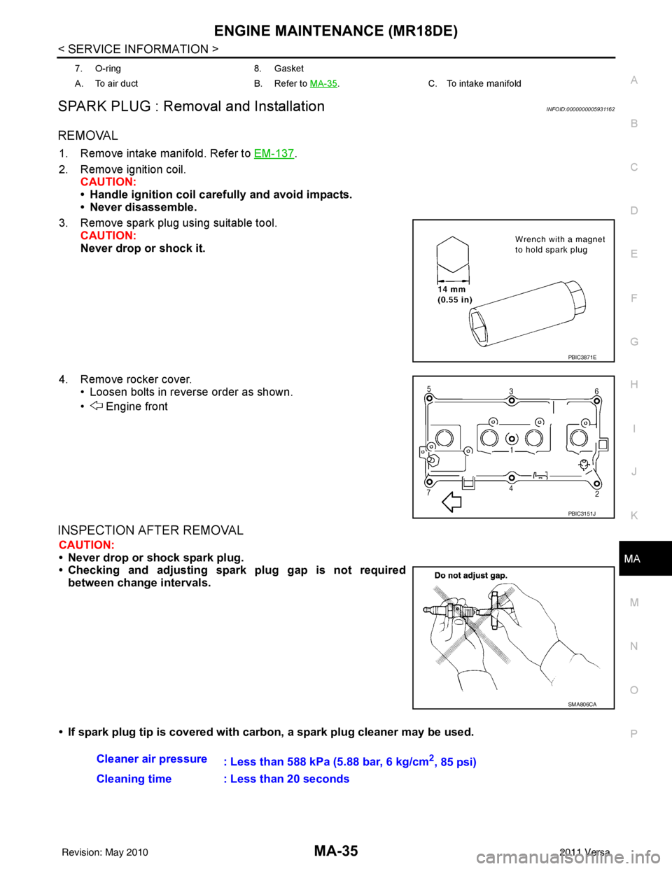
SPARK PLUG : Removal and InstallationINFOID:0000000005931162
REMOVAL
1. Remove intake manifold. Refer to EM-137.
2. Remove ignition coil. CAUTION:
• Handle ignition coil car efully and avoid impacts.
• Never disassemble.
3. Remove spark plug using suitable tool. CAUTION:
Never drop or shock it.
4. Remove rocker cover. • Loosen bolts in reverse order as shown.
• Engine front
INSPECTION AFTER REMOVAL
CAUTION:
• Never drop or shock spark plug.
• Checking and adjusting spar k plug gap is not required
between change intervals.
• If spark plug tip is covered with carbon, a spark plug cleaner may be used.
7. O-ring8. Gasket
A. To air duct B. Refer to MA-35
.C. To intake manifold
PBIC3871E
PBIC3151J
SMA806CA
Cleaner air pressure
: Less than 588 kPa (5.88 bar, 6 kg/cm2, 85 psi)
Cleaning time : Less than 20 seconds
Revision: May 2010 2011 Versa
Page 3207 of 3787
MA-36
< SERVICE INFORMATION >
ENGINE MAINTENANCE (MR18DE)
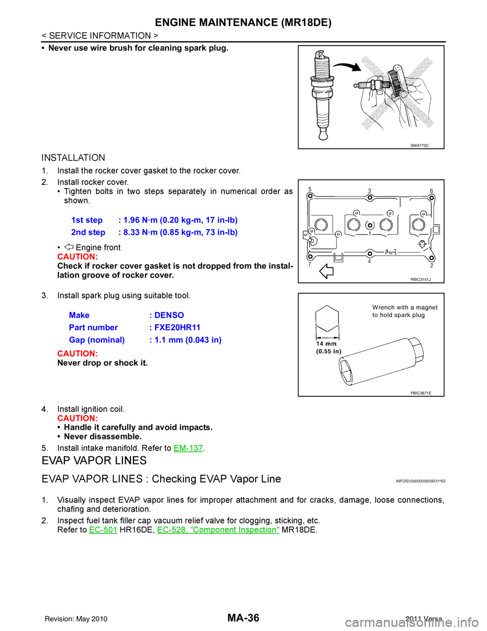
• Never use wire brush for cleaning spark plug.
INSTALLATION
1. Install the rocker cover gasket to the rocker cover.
2. Install rocker cover.• Tighten bolts in two steps separately in numerical order as
shown.
• Engine front
CAUTION:
Check if rocker cover gasket is not dropped from the instal-
lation groove of rocker cover.
3. Install spark plug using suitable tool.
CAUTION:
Never drop or shock it.
4. Install ignition coil. CAUTION:
• Handle it carefully and avoid impacts.
• Never disassemble.
5. Install intake manifold. Refer to EM-137
.
EVAP VAPOR LINES
EVAP VAPOR LINES : Checking EVAP Vapor LineINFOID:0000000005931163
1. Visually inspect EVAP vapor lines for improper attachment and for cracks, damage, loose connections,
chafing and deterioration.
2. Inspect fuel tank filler cap vacuum relief valve for clogging, sticking, etc. Refer to EC-501
HR16DE, EC-528, "Component Inspection" MR18DE.
SMA773C
1st step : 1.96 N·m (0.20 kg-m, 17 in-lb)
2nd step : 8.33 N·m (0.85 kg-m, 73 in-lb)
PBIC3151J
Make : DENSO
Part number : FXE20HR11
Gap (nominal) : 1.1 mm (0.043 in)
PBIC3871E
Revision: May 2010 2011 Versa
Page 3210 of 3787
![NISSAN TIIDA 2011 Service Repair Manual CHASSIS AND BODY MAINTENANCEMA-39
< SERVICE INFORMATION >
C
DE
F
G H
I
J
K
M A
B
MA
N
O P
• : Vehicle front
• Radiator (2)
• CVT fluid cooler hose [inlet side (3)]
• Transaxle assembly (4)
2. NISSAN TIIDA 2011 Service Repair Manual CHASSIS AND BODY MAINTENANCEMA-39
< SERVICE INFORMATION >
C
DE
F
G H
I
J
K
M A
B
MA
N
O P
• : Vehicle front
• Radiator (2)
• CVT fluid cooler hose [inlet side (3)]
• Transaxle assembly (4)
2.](/manual-img/5/57396/w960_57396-3209.png)
CHASSIS AND BODY MAINTENANCEMA-39
< SERVICE INFORMATION >
C
DE
F
G H
I
J
K
M A
B
MA
N
O P
• : Vehicle front
• Radiator (2)
• CVT fluid cooler hose [inlet side (3)]
• Transaxle assembly (4)
2. Drain CVT fluid from CVT fluid cooler hose [outlet side (1)] and refill with new specified NISSAN CVT fluid in the CVT fluid
charging pipe with the engine running at idle speed.
CAUTION:
Only use the specifi ed NISSAN CVT fluid.
3. Refill until new CVT fluid comes out from CVT fluid cooler hose [outlet side (1)]. NOTE:
About 30 to 50% extra fluid will be required for this procedure.
4. Check fluid level and condition. Refer to MA-37, "
CVT FLUID : Checking CVT Fluid".
CAUTION:
Delete CVT fluid deterioration date with CONSULT-III after changing CVT fluid. Refer to CVT-48,
"CONSULT-III Function (TRANSMISSION)".
CLUTCH FLUID
CLUTCH FLUID : Air Bleeding ProcedureINFOID:0000000005931169
CAUTION:
Do not spill clutch fluid onto painted surfaces. If it spills, wipe up immediately and wash the affected
area with water.
NOTE:
• Do not use a vacuum assist or any other type of power bleeder on this system. Use of a vacuum assist or power bleeder will not purge all the air from the system.
• Carefully monitor fluid level in reservoir tank during bleeding operation.
1. Fill master cylinder reservoir tank with new clutch fluid.
2. Connect a transparent vinyl tube and container to the bleeding connector (1) on the CSC.
3. Depress and release the clutch pedal slowly and fully 15 times at an interval of two to three seconds and release the clutch
pedal.
4. Push in the lock pin (1) of the bleeding connector (2), and maintain the position. • RS5F91R transaxle models
CAUTION:
Hold the lock pin in to preven t the bleeding connector from
separating when fluid pressure is applied.
Fluid capacity and grade: Refer to
MA-14, "
Fluids
and Lubricants".SCIA6088E
PCIB1494E
PCIB1495E
Revision: May 2010 2011 Versa
Page 3213 of 3787
MA-42
< SERVICE INFORMATION >
CHASSIS AND BODY MAINTENANCE
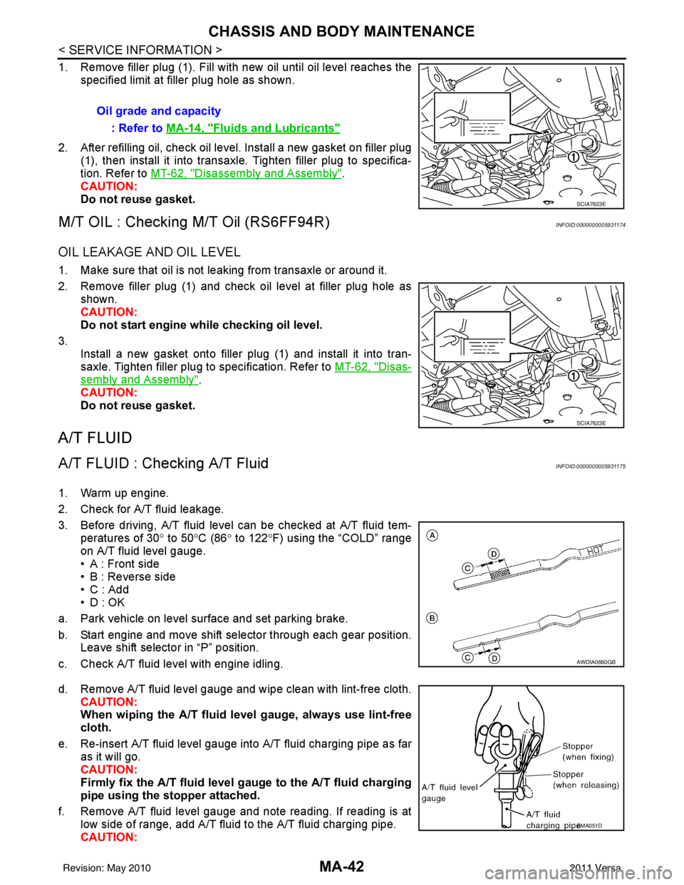
1. Remove filler plug (1). Fill with new oil until oil level reaches thespecified limit at filler plug hole as shown.
2. After refilling oil, check oil level. Install a new gasket on filler plug (1), then install it into transaxle. Tighten filler plug to specifica-
tion. Refer to MT-62, "
Disassembly and Assembly".
CAUTION:
Do not reuse gasket.
M/T OIL : Checking M/T Oil (RS6FF94R)INFOID:0000000005931174
OIL LEAKAGE AND OIL LEVEL
1. Make sure that oil is not leaking from transaxle or around it.
2. Remove filler plug (1) and check oil level at filler plug hole as shown.
CAUTION:
Do not start engine wh ile checking oil level.
3. Install a new gasket onto filler plug (1) and install it into tran-
saxle. Tighten filler plug to specification. Refer to MT-62, "
Disas-
sembly and Assembly".
CAUTION:
Do not reuse gasket.
A/T FLUID
A/T FLUID : Checking A/T FluidINFOID:0000000005931175
1. Warm up engine.
2. Check for A/T fluid leakage.
3. Before driving, A/T fluid level can be checked at A/T fluid tem- peratures of 30 ° to 50 °C (86° to 122° F) using the “COLD” range
on A/T fluid level gauge.
• A : Front side
• B : Reverse side
• C : Add
• D : OK
a. Park vehicle on level surface and set parking brake.
b. Start engine and move shift selector through each gear position. Leave shift selector in “P” position.
c. Check A/T fluid level with engine idling.
d. Remove A/T fluid level gauge and wipe clean with lint-free cloth. CAUTION:
When wiping the A/T fluid level gauge, always use lint-free
cloth.
e. Re-insert A/T fluid level gauge into A/T fluid charging pipe as far as it will go.
CAUTION:
Firmly fix the A/T fluid level gauge to the A/T fluid charging
pipe using the stopper attached.
f. Remove A/T fluid level gauge and note reading. If reading is at low side of range, add A/T fluid to the A/T fluid charging pipe.
CAUTION:Oil grade and capacity
: Refer to MA-14, "
Fluids and Lubricants"
SCIA7623E
SCIA7623E
AWDIA0660GB
SMA051D
Revision: May 2010 2011 Versa
Page 3217 of 3787
MA-46
< SERVICE INFORMATION >
CHASSIS AND BODY MAINTENANCE
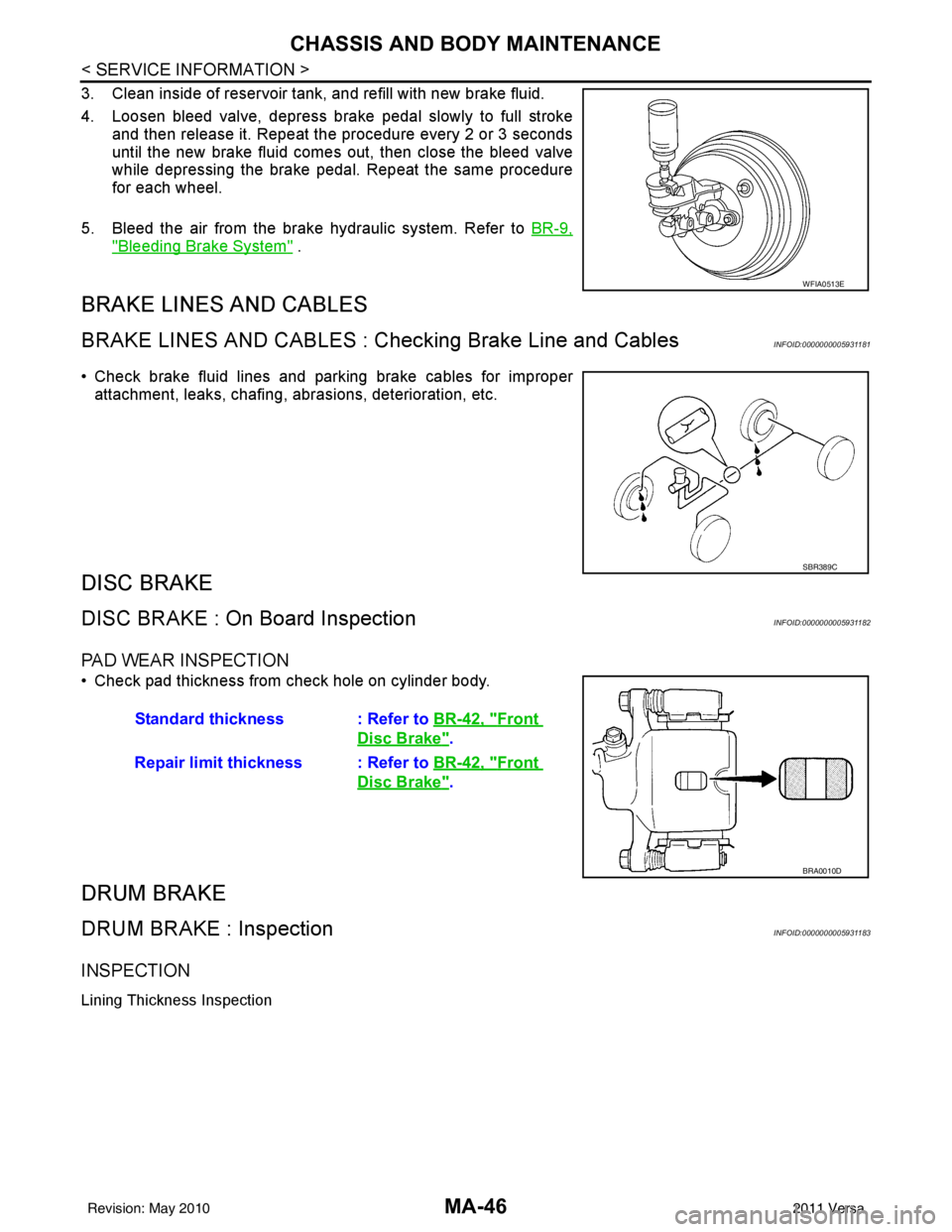
3. Clean inside of reservoir tank, and refill with new brake fluid.
4. Loosen bleed valve, depress brake pedal slowly to full strokeand then release it. Repeat the procedure every 2 or 3 seconds
until the new brake fluid comes out, then close the bleed valve
while depressing the brake pedal. Repeat the same procedure
for each wheel.
5. Bleed the air from the brake hydraulic system. Refer to BR-9,
"Bleeding Brake System" .
BRAKE LINES AND CABLES
BRAKE LINES AND CABLES : Ch ecking Brake Line and CablesINFOID:0000000005931181
• Check brake fluid lines and parking brake cables for improper
attachment, leaks, chafing, abrasions, deterioration, etc.
DISC BRAKE
DISC BRAKE : On Board InspectionINFOID:0000000005931182
PAD WEAR INSPECTION
• Check pad thickness from check hole on cylinder body.
DRUM BRAKE
DRUM BRAKE : InspectionINFOID:0000000005931183
INSPECTION
Lining Thickness Inspection
WFIA0513E
SBR389C
Standard thickness : Refer to BR-42, "Front
Disc Brake".
Repair limit thickness : Refer to BR-42, "
Front
Disc Brake".
BRA0010D
Revision: May 2010 2011 Versa
Page 3218 of 3787
CHASSIS AND BODY MAINTENANCEMA-47
< SERVICE INFORMATION >
C
DE
F
G H
I
J
K
M A
B
MA
N
O P
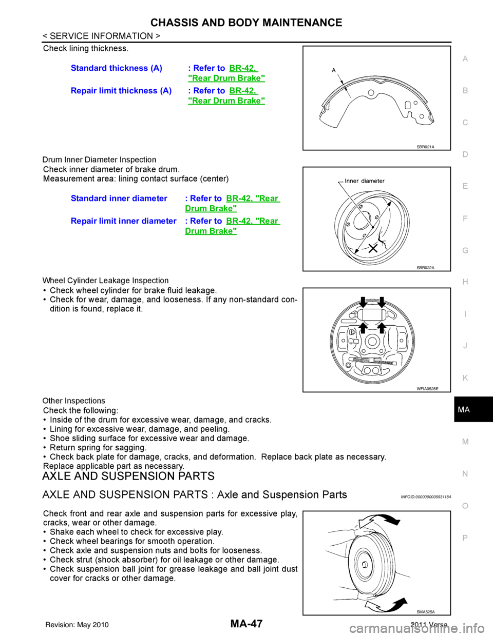
Check lining thickness.
Drum Inner Diameter Inspection
Check inner diameter of brake drum.
Measurement area: lining contact surface (center)
Wheel Cylinder Leakage Inspection
• Check wheel cylinder for brake fluid leakage.
• Check for wear, damage, and looseness. If any non-standard con- dition is found, replace it.
Other Inspections
Check the following:
• Inside of the drum for excessive wear, damage, and cracks.
• Lining for excessive wear, damage, and peeling.
• Shoe sliding surface for excessive wear and damage.
• Return spring for sagging.
• Check back plate for damage, cracks, and deformation. Replace back plate as necessary.
Replace applicable part as necessary.
AXLE AND SUSPENSION PARTS
AXLE AND SUSPENSION PARTS : Axle and Suspension PartsINFOID:0000000005931184
Check front and rear axle and suspension parts for excessive play,
cracks, wear or other damage.
• Shake each wheel to check for excessive play.
• Check wheel bearings for smooth operation.
• Check axle and suspension nuts and bolts for looseness.
• Check strut (shock absorber) for oil leakage or other damage.
• Check suspension ball joint for grease leakage and ball joint dust
cover for cracks or other damage. Standard thickness (A) : Refer to
BR-42,
"Rear Drum Brake"
Repair limit thickness (A) : Refer toBR-42,
"Rear Drum Brake"
SBR021A
Standard inner diameter : Refer toBR-42, "Rear
Drum Brake"
Repair limit inner diameter : Refer toBR-42, "Rear
Drum Brake"
SBR022A
WFIA0528E
SMA525A
Revision: May 2010 2011 Versa
Page 3220 of 3787
CHASSIS AND BODY MAINTENANCEMA-49
< SERVICE INFORMATION >
C
DE
F
G H
I
J
K
M A
B
MA
N
O P
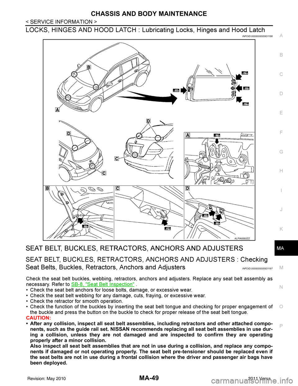
LOCKS, HINGES AND HOOD LATCH : Lubricating Locks, Hinges and Hood Latch
INFOID:0000000005931186
SEAT BELT, BUCKLES, RETRAC TORS, ANCHORS AND ADJUSTERS
SEAT BELT, BUCKLES, RETRACTORS, ANCHORS AND ADJUSTERS : Checking
Seat Belts, Buckles, Retrac tors, Anchors and Adjusters
INFOID:0000000005931187
Check the seat belt buckles, webbing, retractors, anc hors and adjusters. Replace any seat belt assembly as
necessary. Refer to SB-8, "
Seat Belt Inspection" .
• Check the seat belt anchors for loose bolts, damage, or excessive wear.
• Check the seat belt webbing for any damage, cuts, fraying, or excessive wear.
• Check the retractor for smooth operation.
• Check the function of the buckles by inserting the seat belt tongue and checking for proper engagement of
the buckle and press the button on the buckle to c heck for proper release of the seat belt tongue.
CAUTION:
• After any collision, inspect al l seat belt assemblies, including retractors and other attached compo-
nents, such as the guide rail set. NISSAN recomme nds replacing all seat belt assemblies in use dur-
ing a collision, unless they are not damaged an d are inspected to confirm they are operating
properly after a minor collision.
Also inspect all seat belt assemblies that are not in use during a collision, and replace any compo-
nents if damaged or not operating properly. The seat belt pre-tensioner should be replaced even if
the seat belts are not in use during a frontal collision where the driver and passenger air bags have
been deployed.
ALPIA0002ZZ
Revision: May 2010 2011 Versa
Page 3224 of 3787
![NISSAN TIIDA 2011 Service Repair Manual PRECAUTIONSMT-3
< SERVICE INFORMATION > [RS5F91R]
D
E
F
G H
I
J
K L
M A
B
MT
N
O P
SERVICE INFORMATION
PRECAUTIONS
Precaution for Supplemental Restraint System (SRS) "AIR BAG" and "SEAT BELT
PRE-TEN NISSAN TIIDA 2011 Service Repair Manual PRECAUTIONSMT-3
< SERVICE INFORMATION > [RS5F91R]
D
E
F
G H
I
J
K L
M A
B
MT
N
O P
SERVICE INFORMATION
PRECAUTIONS
Precaution for Supplemental Restraint System (SRS) "AIR BAG" and "SEAT BELT
PRE-TEN](/manual-img/5/57396/w960_57396-3223.png)
PRECAUTIONSMT-3
< SERVICE INFORMATION > [RS5F91R]
D
E
F
G H
I
J
K L
M A
B
MT
N
O P
SERVICE INFORMATION
PRECAUTIONS
Precaution for Supplemental Restraint System (SRS) "AIR BAG" and "SEAT BELT
PRE-TENSIONER"
INFOID:0000000005929653
The Supplemental Restraint System such as “AIR BAG” and “SEAT BELT PRE-TENSIONER”, used along
with a front seat belt, helps to reduce the risk or severi ty of injury to the driver and front passenger for certain
types of collision. This system includes seat belt switch inputs and dual stage front air bag modules. The SRS
system uses the seat belt switches to determine the front air bag deployment, and may only deploy one front
air bag, depending on the severity of a collision and w hether the front occupants are belted or unbelted.
Information necessary to service the system safely is included in the SRS and SB section of this Service Man-
ual.
WARNING:
• To avoid rendering the SRS inoper ative, which could increase the risk of personal injury or death in
the event of a collision which would result in air bag inflation, all maintenance must be performed by
an authorized NISSAN/INFINITI dealer.
• Improper maintenance, including in correct removal and installation of the SRS can lead to personal
injury caused by unintentional act ivation of the system. For removal of Spiral Cable and Air Bag
Module, see the SRS section.
• Do not use electrical test equipm ent on any circuit related to the SRS unless instructed to in this
Service Manual. SRS wiring harnesses can be identi fied by yellow and/or orange harnesses or har-
ness connectors.
PRECAUTIONS WHEN USING POWER TOOLS (AIR OR ELECTRIC) AND HAMMERS
WARNING:
• When working near the Airbag Diagnosis Sensor Un it or other Airbag System sensors with the Igni-
tion ON or engine running, DO NOT use air or el ectric power tools or strike near the sensor(s) with a
hammer. Heavy vibration could activate the sensor( s) and deploy the air bag(s), possibly causing
serious injury.
• When using air or electric power tools or hammers, always switch the Ignition OFF, disconnect the battery, and wait at least 3 minutes before performing any service.
Precaution Necessary for Steering Wheel Rotation After Battery Disconnect
INFOID:0000000005929654
NOTE:
• This Procedure is applied only to models with Intelligent Key system and NATS (NISSAN ANTI-THEFT SYS-
TEM).
• Remove and install all control units after disconnecti ng both battery cables with the ignition knob in the
″ LOCK ″ position.
• Always use CONSULT-III to perform self-diagnosis as a part of each function inspection after finishing work.
If DTC is detected, perform trouble diagnosis according to self-diagnostic results.
For models equipped with the Intelligent Key system and NATS , an electrically controlled steering lock mech-
anism is adopted on the key cylinder.
For this reason, if the battery is disconnected or if the battery is discharged, the steering wheel will lock and
steering wheel rotation will become impossible.
If steering wheel rotation is required when battery power is interrupted, follow the procedure below before
starting the repair operation.
OPERATION PROCEDURE
1. Connect both battery cables. NOTE:
Supply power using jumper cables if battery is discharged.
2. Use the Intelligent Key or mechanical key to turn the ignition switch to the ″ACC ″ position. At this time, the
steering lock will be released.
3. Disconnect both battery cables. The steering lock will remain released and the steering wheel can be
rotated.
4. Perform the necessary repair operation.
Revision: May 2010 2011 Versa