2011 NISSAN TIIDA check oil
[x] Cancel search: check oilPage 865 of 3787
BR-18
< SERVICE INFORMATION >
BRAKE MASTER CYLINDER
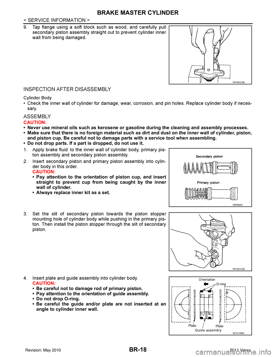
9. Tap flange using a soft block such as wood, and carefully pullsecondary piston assembly straight out to prevent cylinder inner
wall from being damaged.
INSPECTION AFTER DISASSEMBLY
Cylinder Body
• Check the inner wall of cylinder for damage, wear, corrosion, and pin holes. Replace cylinder body if neces-sary.
ASSEMBLY
CAUTION:
• Never use mineral oils such as kerosene or g asoline during the cleaning and assembly processes.
• Make sure that there is no foreign material such as dirt and dust on the inner wall of cylinder, piston,
and piston cup. Be careful not to damage parts with a service tool when assembling.
• Do not drop parts. If a part is dropped, do not use it.
1. Apply brake fluid to the inner wall of cylinder body, primary pis- ton assembly and secondary piston assembly.
2. Insert secondary piston and primary piston assembly into cylin- der body in this order.
CAUTION:
• Pay attention to the orientation of piston cup, and insert
straight to prevent cup from being caught by the inner
wall of cylinder.
• Always replace inner kit as a set.
3. Set the slit of secondary piston towards the piston stopper mounting hole of cylinder body while pushing in the primary pis-
ton. Then install the piston stopper through the slit of secondary
piston.
4. Insert plate and guide assembly into cylinder body. CAUTION:
• Be careful not to damage rod of primary piston.
• Pay attention to the orientation of guide assembly.
• Do not drop O-ring.
• Be careful the guide and/or plate are not inserted at an
angle to cylinder inner wall.
WFIA0518E
SBR089C
WFIA0516E
SFIA1469E
Revision: May 2010 2011 Versa
Page 870 of 3787
VACUUM LINESBR-23
< SERVICE INFORMATION >
C
DE
G H
I
J
K L
M A
B
BR
N
O P
VACUUM LINES
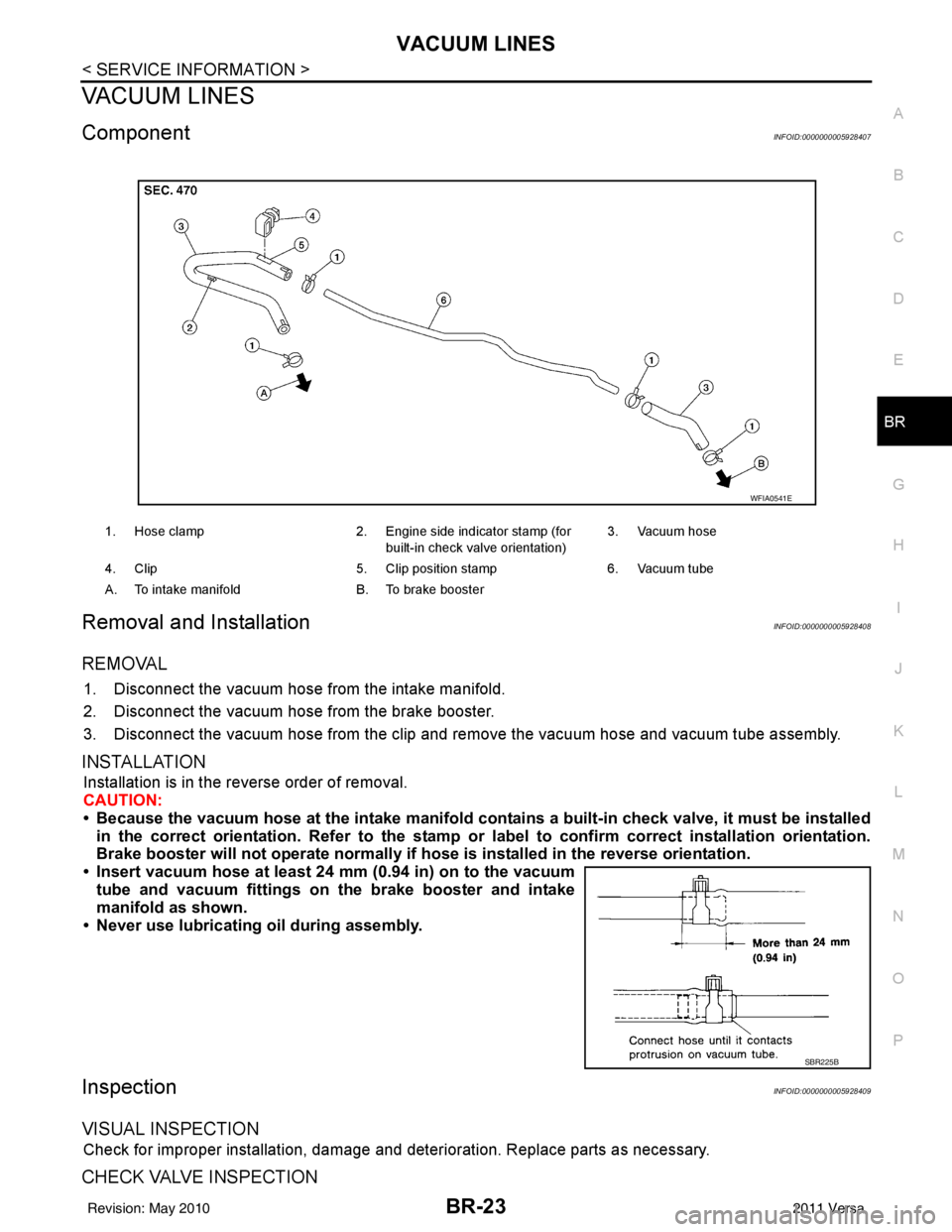
ComponentINFOID:0000000005928407
Removal and InstallationINFOID:0000000005928408
REMOVAL
1. Disconnect the vacuum hose from the intake manifold.
2. Disconnect the vacuum hose from the brake booster.
3. Disconnect the vacuum hose from the clip and re move the vacuum hose and vacuum tube assembly.
INSTALLATION
Installation is in the reverse order of removal.
CAUTION:
• Because the vacuum hose at the intake manifold contains a built-in check valve, it must be installed
in the correct orientation. Refer to the stamp or label to confirm correct installation orientation.
Brake booster will not operate normally if ho se is installed in the reverse orientation.
• Insert vacuum hose at least 24 mm (0.94 in) on to the vacuum tube and vacuum fittings on the brake booster and intake
manifold as shown.
• Never use lubricating oil during assembly.
InspectionINFOID:0000000005928409
VISUAL INSPECTION
Check for improper installation, damage and deterioration. Replace parts as necessary.
CHECK VALVE INSPECTION
1. Hose clamp 2. Engine side indicator stamp (for
built-in check valve orientation) 3. Vacuum hose
4. Clip 5. Clip position stamp6. Vacuum tube
A. To intake manifold B. To brake booster
WFIA0541E
SBR225B
Revision: May 2010 2011 Versa
Page 879 of 3787
BR-32
< SERVICE INFORMATION >
FRONT DISC BRAKE
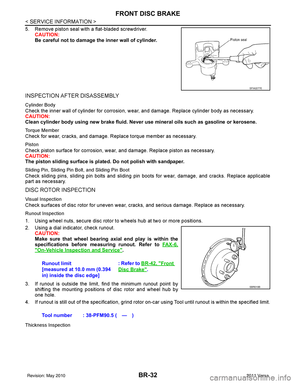
5. Remove piston seal with a flat-bladed screwdriver.CAUTION:
Be careful not to damage the inner wall of cylinder.
INSPECTION AFTER DISASSEMBLY
Cylinder Body
Check the inner wall of cylinder for corrosion, w ear, and damage. Replace cylinder body as necessary.
CAUTION:
Clean cylinder body using new brake fluid. Never use mineral oils such as gasoline or kerosene.
Torque Member
Check for wear, cracks, and damage. R eplace torque member as necessary.
Piston
Check piston surface for corrosion, wear, and damage. Replace piston as necessary.
CAUTION:
The piston sliding surface is plated. Do not polish with sandpaper.
Sliding Pin, Sliding Pin Bolt, and Sliding Pin Boot
Check sliding pins, sliding pin bolts and sliding pin boots for wear, damage, and cracks. Replace applicable
part as necessary.
DISC ROTOR INSPECTION
Visual Inspection
Check surfaces of disc rotor for uneven wear, cr acks, and serious damage. Replace as necessary.
Runout Inspection
1. Using wheel nuts, secure disc rotor to wheels hub at two or more positions.
2. Using a dial indicator, check runout.
CAUTION:
Make sure that wheel bearing axial end play is within the
specifications before measuring runout. Refer to FA X - 6 ,
"On-Vehicle Inspection and Service".
3. If runout is outside the limit, find the minimum runout point by shifting the mounting positions of disc rotor and wheel hub by
one hole.
4. If runout is still out of the specification, grind rotor on-car using Tool until runout is within the specified limit.
Thickness Inspection
SFIA2277E
Runout limit
[measured at 10.0 mm (0.394
in) inside the disc edge] : Refer to BR-42, "Front
Disc Brake".
Tool number : 38-PFM90.5 ( — )
SBR019B
Revision: May 2010 2011 Versa
Page 928 of 3787
![NISSAN TIIDA 2011 Service Repair Manual PRECAUTIONSBRC-39
< SERVICE INFORMATION > [VDC/TCS/ABS]
C
D
E
G H
I
J
K L
M A
B
BRC
N
O P
5. When the repair work is completed, re-connect both battery cables. With the brake pedal released, turn the](/manual-img/5/57396/w960_57396-927.png "NISSAN TIIDA 2011 Service Repair Manual PRECAUTIONSBRC-39
< SERVICE INFORMATION > [VDC/TCS/ABS]
C
D
E
G H
I
J
K L
M A
B
BRC
N
O P
5. When the repair work is completed, re-connect both battery cables. With the brake pedal released, turn the")
PRECAUTIONSBRC-39
< SERVICE INFORMATION > [VDC/TCS/ABS]
C
D
E
G H
I
J
K L
M A
B
BRC
N
O P
5. When the repair work is completed, re-connect both battery cables. With the brake pedal released, turn the push-button ignition switch from ACC position to ON position, then to LOCK position. (The steering
wheel will lock when the push-button ignition switch is turned to LOCK position.)
6. Perform self-diagnosis check of a ll control units using CONSULT-III.
Precaution for Brake SystemINFOID:0000000005928462
CAUTION:
• Refer to MA-14, "
Fluids and Lubricants" for recommended brake fluid.
• Never reuse drained brake fluid.
• Be careful not to splash brake fluid on painted areas; it may cause paint damage. If brake fluid is
splashed on painted areas, wash it away with water immediately.
• To clean or wash all parts of master cylin der and disc brake caliper, use clean brake fluid.
• Never use mineral oils such as gasoline or kerosen e. They will ruin rubber parts of the hydraulic sys-
tem.
• Use flare nut wrench when removing and installing brake tube.
• If a brake fluid leak is found, the part must be disassembled
without fail. Then it has to be replaced with a new one if a
defect exists.
• Turn the ignition switch OFF and remove the connector of the
ABS actuator and electric unit (con trol unit) or the battery ter-
minal before performing the work.
• Always torque brake lines when installing.
• Burnish the brake contact surf aces after refinishing or replac-
ing rotors, after replacing pads, or if a soft pedal occurs at
very low mileage.
Refer to BR-34, "
Brake Burnishing Procedure".
WARNING:
• Clean brake pads and shoes with a waste cl oth, then wipe with a dust collector.
Precaution for Brake ControlINFOID:0000000005928463
• During ABS operation, the brake pedal may vibrate lightly and a mechanical noise may be heard. This is
normal.
• Just after starting vehicle, the brake pedal may vibrate or a motor operating noise may be heard from engine
compartment. This is a normal status of operation check.
• Stopping distance may be longer than that of vehicles without ABS when vehicle drives on rough, gravel, or snow-covered (fresh, deep snow) roads.
• When an error is indicated by ABS or another warning lamp, collect all necessary information from customer (what symptoms are present under what conditions) and check for simple causes before starting diagnosis.
Besides electrical system inspection, check boos ter operation, brake fluid level, and fluid leaks.
• If incorrect tire sizes or types are installed on the vehicle or brake pads are not Genuine NISSAN parts, stop-
ping distance or steering stability may deteriorate.
• If there is a radio, antenna or related wiring near control module, ABS function may have a malfunction or
error.
• If aftermarket parts (car stereo, CD player, etc.) have been installed, check for incidents such as harness pinches, open circuits or improper wiring.
• If the following components are replaced with non-genuine components or modified, the VDC OFF indicator lamp and SLIP indicator lamp may turn on or the VDC system may not operate properly. Components
related to suspension (shock absorbers, struts, springs , bushings, etc.), tires, wheels (exclude specified
size), components related to brake system (pads, roto rs, calipers, etc.), components related to engine (muf-
fler, ECM, etc.), components related to body reinforcement (roll bar, tower bar, etc.).
• Driving with broken or excessively worn suspensi on components, tires or brake system components may
cause the VDC OFF indicator lamp and the SLIP indicator lamp to turn on, and the VDC system may not
operate properly.
• When the TCS or VDC is activated by sudden acceleration or sudden turn, some noise may occur. The noise is a result of the normal operation of the TCS and VDC.
• When driving on roads which have extreme slopes (such as mountainous roads) or high banks (such as sharp curves on a freeway), the VDC may not operate no rmally, or the VDC warning lamp and the SLIP indi-
cator lamp may turn on. This is not a problem if normal operation can be resumed after restarting the engine.
SBR686C
Revision: May 2010 2011 Versa
Page 984 of 3787
PRECAUTIONSCL-3
< SERVICE INFORMATION >
DE
F
G H
I
J
K L
M A
B
CL
N
O P
5. When the repair work is completed, return the ignition switch to the ″LOCK ″ position before connecting
the battery cables. (At this time, the steering lock mechanism will engage.)
6. Perform a self-diagnosis check of al l control units using CONSULT-III.
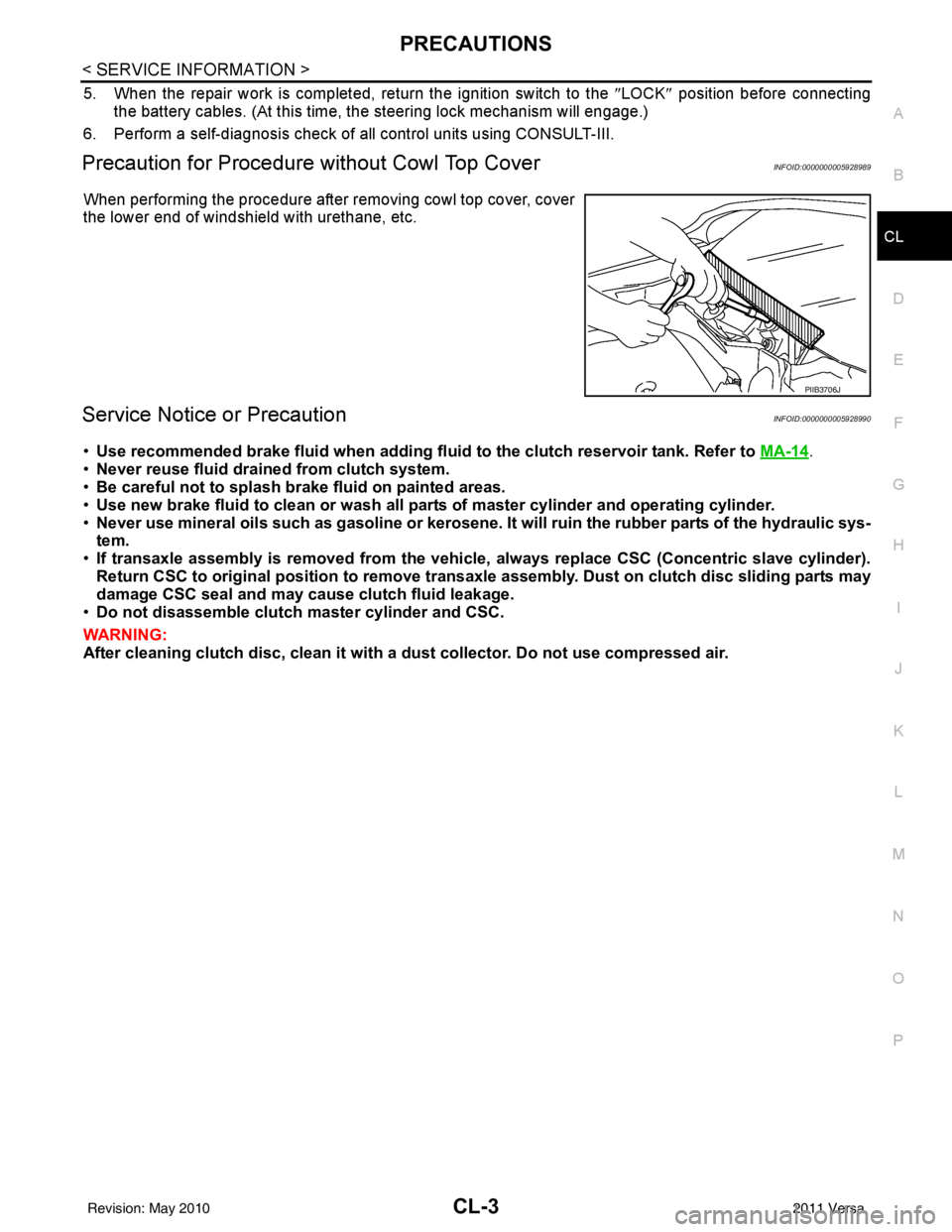
Precaution for Procedure without Cowl Top CoverINFOID:0000000005928989
When performing the procedure after removing cowl top cover, cover
the lower end of windshield with urethane, etc.
Service Notice or PrecautionINFOID:0000000005928990
•Use recommended brake fluid when adding fluid to the clutch reservoir tank. Refer to MA-14.
• Never reuse fluid drained from clutch system.
• Be careful not to splash brake fluid on painted areas.
• Use new brake fluid to clean or wash all part s of master cylinder and operating cylinder.
• Never use mineral oils such as gasoline or kerosene. It will ruin the rubber parts of the hydraulic sys-
tem.
• If transaxle assembly is removed from the vehicle, always replace CSC (Con centric slave cylinder).
Return CSC to original position to remove transaxle assembly. Dust on clutch disc sliding parts may
damage CSC seal and may cause clutch fluid leakage.
• Do not disassemble clutch master cylinder and CSC.
WARNING:
After cleaning clutch disc, cl ean it with a dust collector. Do not use compressed air.
PIIB3706J
Revision: May 2010 2011 Versa
Page 997 of 3787
CL-16
< SERVICE INFORMATION >
CLUTCH DISC, CLUTCH COVER AND FLYWHEEL
CLUTCH DISC, CLUTCH COVER AND FLYWHEEL
Removal and InstallationINFOID:0000000005929001
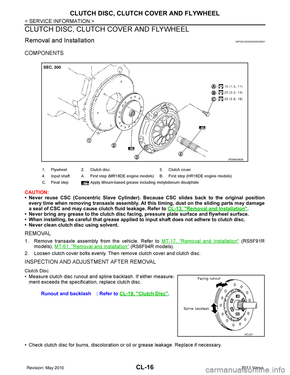
COMPONENTS
CAUTION:
• Never reuse CSC (Concentric Slave Cylinder). Because CSC slides back to the original position
every time when removing transaxle assembly. At this timing, dust on the sliding parts may damage
a seal of CSC and may cause clutch fluid leakage. Refer to CL-13, "
Removal and Installation".
• Never bring any grease to the clutch disc faci ng, pressure plate surface and flywheel surface.
• When installing, be careful that grease applied to input shaft does not adhere to clutch disc.
• Never clean clutch disc using solvent.
REMOVAL
1. Remove transaxle assembly from the vehicle. Refer to MT-17, "Removal and Installation" (RS5F91R
models), MT-61, "
Removal and Installation" (RS6F94R models).
2. Loosen clutch cover bolts evenly. Then remove clutch cover and clutch disc.
INSPECTION AND ADJUSTMENT AFTER REMOVAL
Clutch Disc
• Measure clutch disc runout and spline backlash. If either measure- ment exceeds the specificat ion, replace clutch disc.
• Check clutch disc for burns, discoloration or oil or grease leakage. Replace if necessary.
1. Flywheel 2. Clutch disc 3. Clutch cover
4. Input shaft A. First step (MR18DE engine models) B. First step (HR16DE engine models)
C. Final step Apply lithium-based grease including molybdenum disulphide
JPDIB0038GB
Runout and backlash : Refer to CL-19, "Clutch Disc".
SCL221
Revision: May 2010 2011 Versa
Page 1014 of 3787
![NISSAN TIIDA 2011 Service Repair Manual CO-14
< ON-VEHICLE MAINTENANCE >[HR16DE]
RADIATOR
RADIATOR
Checking Radiator CapINFOID:0000000005930779
• Check valve seat of radiator cap.
- Check if valve seat is swollen to the extent that the e](/manual-img/5/57396/w960_57396-1013.png "NISSAN TIIDA 2011 Service Repair Manual CO-14
< ON-VEHICLE MAINTENANCE >[HR16DE]
RADIATOR
RADIATOR
Checking Radiator CapINFOID:0000000005930779
• Check valve seat of radiator cap.
- Check if valve seat is swollen to the extent that the e")
CO-14
< ON-VEHICLE MAINTENANCE >[HR16DE]
RADIATOR
RADIATOR
Checking Radiator CapINFOID:0000000005930779
• Check valve seat of radiator cap.
- Check if valve seat is swollen to the extent that the edge of the
plunger cannot be seen when watching it vertically from the top.
- Check if valve seat has no soil and damage.
• Pull negative-pressure valve to open it, and make sure that it is completely closed when released.
- Make sure that there is no dirt or damage on the valve seat of radi-
ator cap negative-pressure valve.
- Make sure that the valve operates properly in the opening and closing conditions.
• Check radiator cap relief pressure using suitable tool and Tool.
- When connecting the radiator cap to the tester, apply water or coolant to the cap seal surface.
- Replace the radiator cap if ther e is an abnormality in the negative-
pressure valve, or if the open-valve pr essure is outside of the standard values.
• Replace radiator cap if there it does not comply to specifications to the above three checks.
CAUTION:
When installing radiator cap, thoroughly wipe out the radiator filler neck to remove any waxy residue
or foreign material.
Checking RadiatorINFOID:0000000005930780
Check radiator for mud or clogging. If necessary, clean radiator as follows.
• Be careful not to bend or damage radiator fins.
• When radiator is cleaned without removal, remove all surrounding parts such as cooling fan, radiator shroud and horns. Then tape harness and connectors to prevent water from entering.
1. Apply water by hose to the back side of the radiator core vertically downward.
2. Apply water again to all radiator core surface once per minute.
3. Stop washing if any stains no longer flow out from radiator.
4. Blow air into the back side of radiator core vertically downward.
PBIC2816E
SMA967B
Tool number : EG17650301 (J-33984-A)
Standard: 78 – 98 kPa (0.78 - 0.98 bar, 0.8 – 1.0 kg/cm
2, 11
– 14 psi)
Limit: 59 kPa (0.59 bar, 0.6 kg/cm
2, 9 psi)
WBIA0570E
Revision: May 2010 2011 Versa
Page 1023 of 3787
![NISSAN TIIDA 2011 Service Repair Manual THERMOSTATCO-23
< ON-VEHICLE REPAIR > [HR16DE]
C
D
E
F
G H
I
J
K L
M A
CO
NP
O
• Install thermostat (2) into the cylinder block (1) with jiggle valve (A)
facing upwards.
Water Inlet.
After installa](/manual-img/5/57396/w960_57396-1022.png "NISSAN TIIDA 2011 Service Repair Manual THERMOSTATCO-23
< ON-VEHICLE REPAIR > [HR16DE]
C
D
E
F
G H
I
J
K L
M A
CO
NP
O
• Install thermostat (2) into the cylinder block (1) with jiggle valve (A)
facing upwards.
Water Inlet.
After installa")
THERMOSTATCO-23
< ON-VEHICLE REPAIR > [HR16DE]
C
D
E
F
G H
I
J
K L
M A
CO
NP
O
• Install thermostat (2) into the cylinder block (1) with jiggle valve (A)
facing upwards.
Water Inlet.
After installation, fix water inlet clip (A) on the oil level gauge guide
(1) positioned (B) as shown.
InspectionINFOID:0000000005930792
INSPECTION AFTER REMOVAL
WARNING:
Use a protector to prevent a burn during the work.
Thermostat
• Place a thread (A) so that it is caught in the valves of thermostat(1). Immerse fully in a container (B) filled with water. Heat while
stirring.
• The valve opening temperature is the temperature at which the valve opens and falls from the thread.
• Continue heating. Check the full-open valve lift amount.
• After checking the full-open valve lift amount, lower the water tem- perature and check the valve closing temperature.
• If out of the standard, replace thermostat.
INSPECTION AFTER INSTALLATION
• Check that the reservoir tank cap is tightened.
• Check for leaks of engine coolant using suitable tools. Refer to CO-11, "
Inspection".
• Start and warm up the engine. Visually make sure that there is no leaks of engine coolant.
PBIC3812E
PBIC3755E
Standard : Refer to CO-26, "Thermostat".
PBIC3314J
Revision: May 2010 2011 Versa