Page 303 of 3787
AT-286
< SERVICE INFORMATION >
REPAIR FOR COMPONENT PARTS
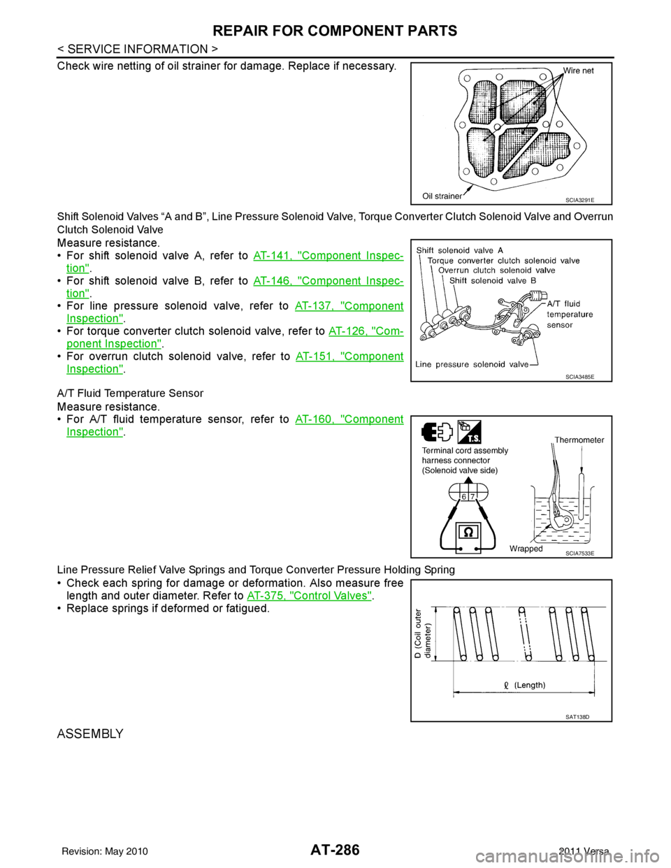
Check wire netting of oil strainer for damage. Replace if necessary.
Shift Solenoid Valves “A and B”, Line Pressure Solenoid Valve, Torque Converter Clutch Solenoid Valve and Overrun
Clutch Solenoid Valve
Measure resistance.
• For shift solenoid valve A, refer to AT-141, "
Component Inspec-
tion".
• For shift solenoid valve B, refer to AT-146, "
Component Inspec-
tion".
• For line pressure solenoid valve, refer to AT-137, "
Component
Inspection".
• For torque converter clutch solenoid valve, refer to AT-126, "
Com-
ponent Inspection".
• For overrun clutch solenoid valve, refer to AT-151, "
Component
Inspection".
A/T Fluid Temperature Sensor
Measure resistance.
• For A/T fluid temperature sensor, refer to AT-160, "
Component
Inspection".
Line Pressure Relief Valve Springs and Torque Converter Pressure Holding Spring
• Check each spring for damage or deformation. Also measure free
length and outer diameter. Refer to AT-375, "
Control Valves".
• Replace springs if deformed or fatigued.
ASSEMBLY
SCIA3291E
SCIA3485E
SCIA7533E
SAT138D
Revision: May 2010 2011 Versa
Page 315 of 3787
AT-298
< SERVICE INFORMATION >
REPAIR FOR COMPONENT PARTS
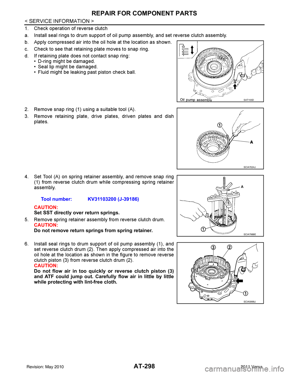
1. Check operation of reverse clutch
a. Install seal rings to drum support of oil pump assembly, and set reverse clutch assembly.
b. Apply compressed air into the oil hole at the location as shown.
c. Check to see that retaining plate moves to snap ring.
d. If retaining plate does not contact snap ring:• D-ring might be damaged.
• Seal lip might be damaged.
• Fluid might be leaking past piston check ball.
2. Remove snap ring (1) using a suitable tool (A).
3. Remove retaining plate, drive plates, driven plates and dish plates.
4. Set Tool (A) on spring retainer assembly, and remove snap ring (1) from reverse clutch drum while compressing spring retainer
assembly.
CAUTION:
Set SST directly over return springs.
5. Remove spring retainer assembly from reverse clutch drum. CAUTION:
Do not remove return springs from spring retainer.
6. Install seal rings to drum support of oil pump assembly (1), and set reverse clutch drum (2). Then apply compressed air into the
oil hole at the location as shown in the figure to remove reverse
clutch piston (3) from reverse clutch drum (2).
CAUTION:
Do not flow air in too quickl y or reverse clutch piston (3)
and ATF could jump out. Carefully flow air in little by little
while protecting wi th lint-free cloth.
SAT155D
SCIA7024J
Tool number: KV31103200 (J-39186)
SCIA7988E
SCIA5999J
Revision: May 2010 2011 Versa
Page 317 of 3787
AT-300
< SERVICE INFORMATION >
REPAIR FOR COMPONENT PARTS
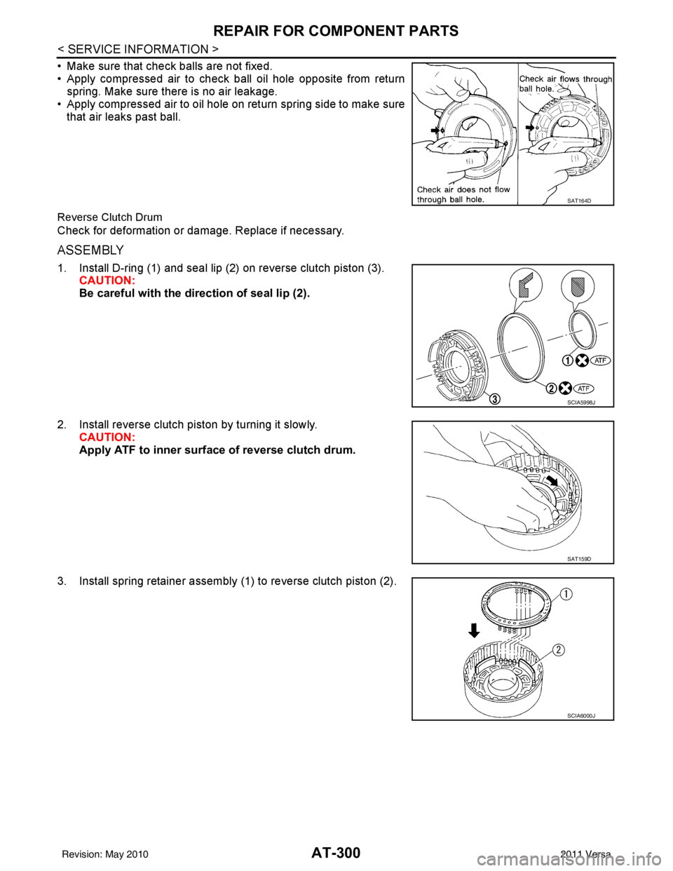
• Make sure that check balls are not fixed.
• Apply compressed air to check ball oil hole opposite from returnspring. Make sure there is no air leakage.
• Apply compressed air to oil hole on return spring side to make sure that air leaks past ball.
Reverse Clutch Drum
Check for deformation or damage. Replace if necessary.
ASSEMBLY
1. Install D-ring (1) and seal lip (2) on reverse clutch piston (3). CAUTION:
Be careful with the direction of seal lip (2).
2. Install reverse clutch piston by turning it slowly. CAUTION:
Apply ATF to inner surface of reverse clutch drum.
3. Install spring retainer assembly (1) to reverse clutch piston (2).
SAT164D
SCIA5998J
SAT159D
SCIA6000J
Revision: May 2010 2011 Versa
Page 319 of 3787
AT-302
< SERVICE INFORMATION >
REPAIR FOR COMPONENT PARTS
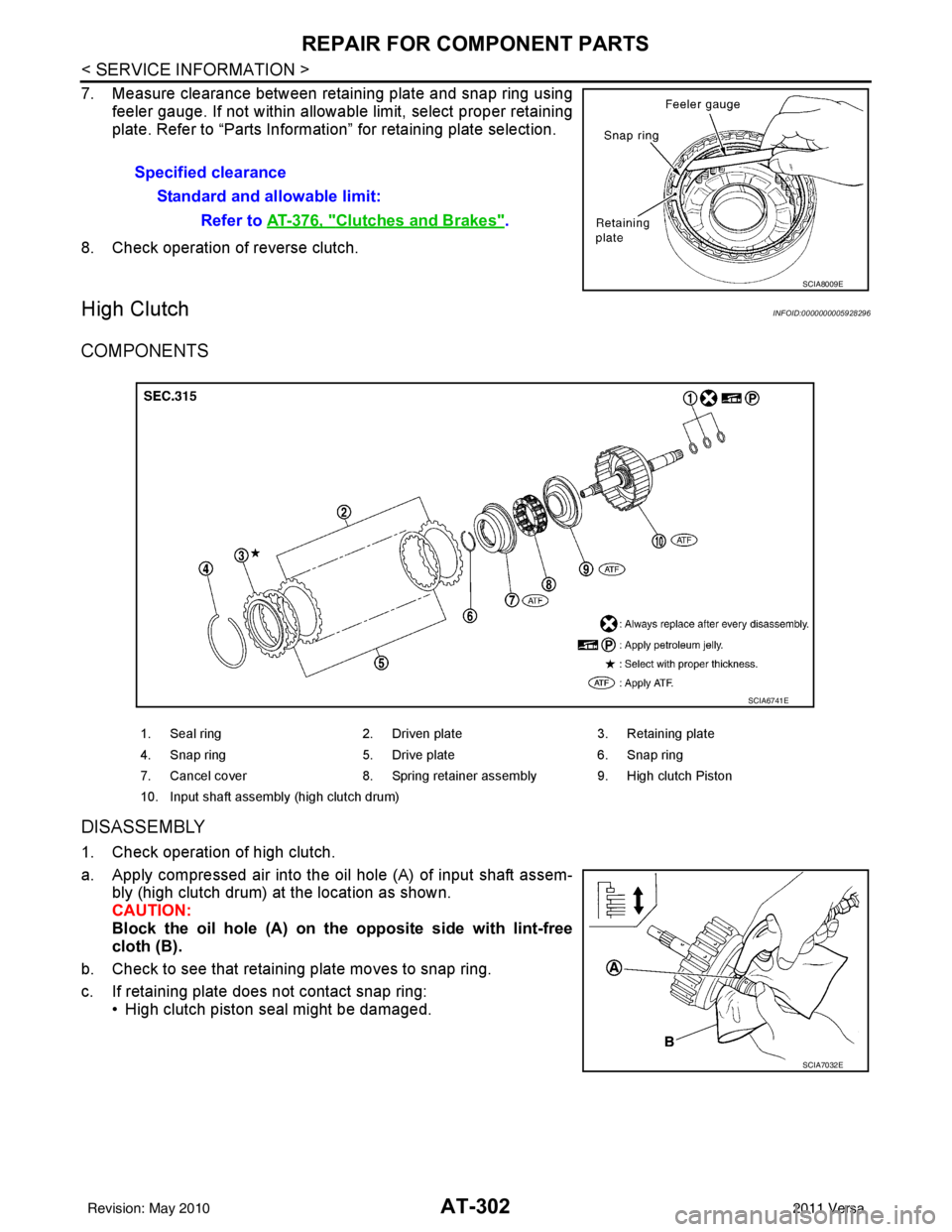
7. Measure clearance between retaining plate and snap ring usingfeeler gauge. If not within allowable limit, select proper retaining
plate. Refer to “Parts Information” for retaining plate selection.
8. Check operation of reverse clutch.
High ClutchINFOID:0000000005928296
COMPONENTS
DISASSEMBLY
1. Check operation of high clutch.
a. Apply compressed air into the oil hole (A) of input shaft assem- bly (high clutch drum) at the location as shown.
CAUTION:
Block the oil hole (A) on the opposite side with lint-free
cloth (B).
b. Check to see that retaining plate moves to snap ring.
c. If retaining plate does not contact snap ring: • High clutch piston seal might be damaged.Specified clearance
Standard and allowable limit: Refer to AT-376, "
Clutches and Brakes".
SCIA8009E
1. Seal ring 2. Driven plate 3. Retaining plate
4. Snap ring 5. Drive plate 6. Snap ring
7. Cancel cover 8. Spring retainer assembly 9. High clutch Piston
10. Input shaft assembly (high clutch drum)
SCIA6741E
SCIA7032E
Revision: May 2010 2011 Versa
Page 325 of 3787
AT-308
< SERVICE INFORMATION >
REPAIR FOR COMPONENT PARTS
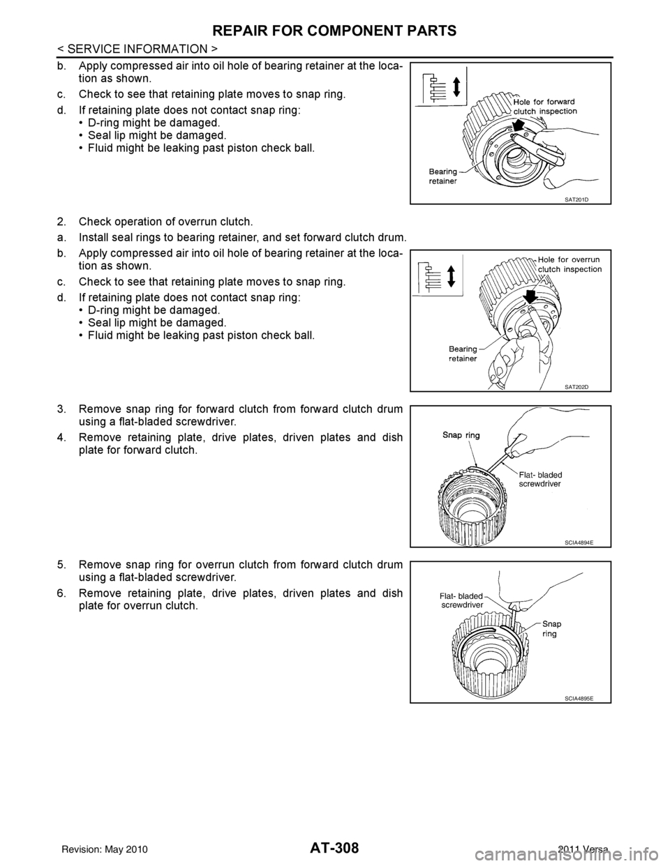
b. Apply compressed air into oil hole of bearing retainer at the loca-tion as shown.
c. Check to see that retaining plate moves to snap ring.
d. If retaining plate does not contact snap ring: • D-ring might be damaged.
• Seal lip might be damaged.
• Fluid might be leaking past piston check ball.
2. Check operation of overrun clutch.
a. Install seal rings to bearing retainer, and set forward clutch drum.
b. Apply compressed air into oil hole of bearing retainer at the loca- tion as shown.
c. Check to see that retaining plate moves to snap ring.
d. If retaining plate does not contact snap ring: • D-ring might be damaged.
• Seal lip might be damaged.
• Fluid might be leaking past piston check ball.
3. Remove snap ring for forward clutch from forward clutch drum using a flat-bladed screwdriver.
4. Remove retaining plate, drive plates, driven plates and dish plate for forward clutch.
5. Remove snap ring for overrun clutch from forward clutch drum using a flat-bladed screwdriver.
6. Remove retaining plate, drive plates, driven plates and dish plate for overrun clutch.
SAT201D
SAT202D
SCIA4894E
SCIA4895E
Revision: May 2010 2011 Versa
Page 326 of 3787
REPAIR FOR COMPONENT PARTSAT-309
< SERVICE INFORMATION >
DE
F
G H
I
J
K L
M A
B
AT
N
O P
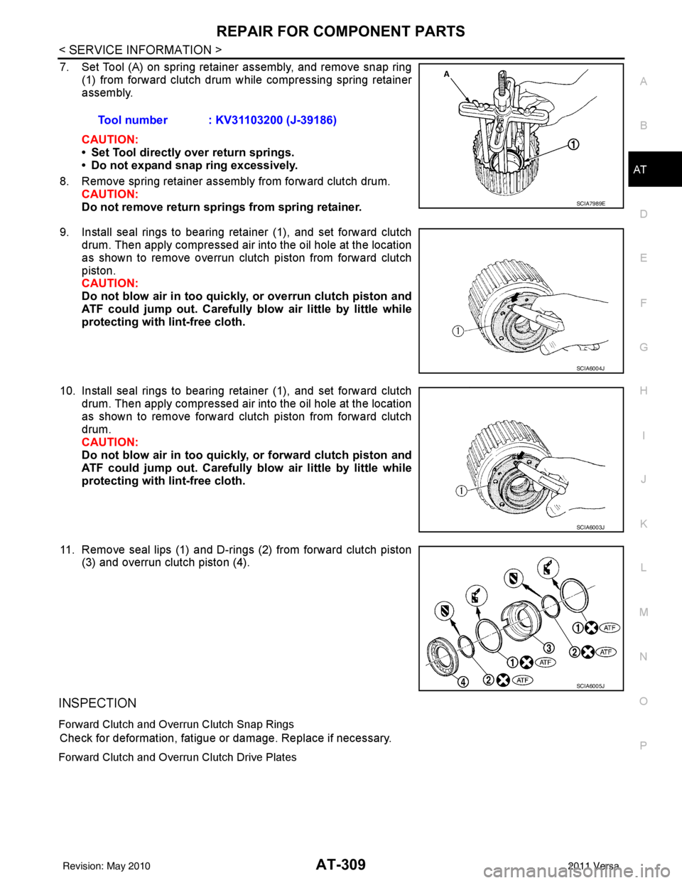
7. Set Tool (A) on spring retainer assembly, and remove snap ring (1) from forward clutch drum while compressing spring retainer
assembly.
CAUTION:
• Set Tool directly over return springs.
• Do not expand snap ring excessively.
8. Remove spring retainer assembly from forward clutch drum. CAUTION:
Do not remove return springs from spring retainer.
9. Install seal rings to bearing retainer (1), and set forward clutch drum. Then apply compressed air into the oil hole at the location
as shown to remove overrun clutch piston from forward clutch
piston.
CAUTION:
Do not blow air in too quickly, or overrun clutch piston and
ATF could jump out. Carefully blow air little by little while
protecting with lint-free cloth.
10. Install seal rings to bearing retainer (1), and set forward clutch drum. Then apply compressed air into the oil hole at the location
as shown to remove forward clutch piston from forward clutch
drum.
CAUTION:
Do not blow air in too quickly, or forward clutch piston and
ATF could jump out. Carefully blow air little by little while
protecting with lint-free cloth.
11. Remove seal lips (1) and D-rings (2) from forward clutch piston (3) and overrun clutch piston (4).
INSPECTION
Forward Clutch and Overrun Clutch Snap Rings
Check for deformation, fatigue or damage. Replace if necessary.
Forward Clutch and Overrun Clutch Drive Plates
Tool number : KV31103200 (J-39186)
SCIA7989E
SCIA6004J
SCIA6003J
SCIA6005J
Revision: May 2010 2011 Versa
Page 327 of 3787
AT-310
< SERVICE INFORMATION >
REPAIR FOR COMPONENT PARTS
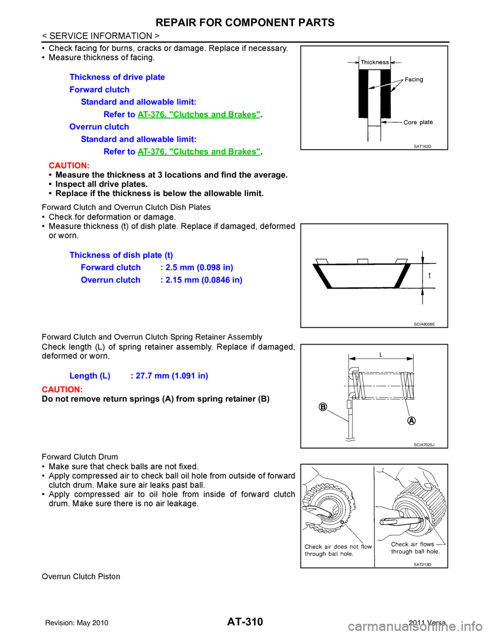
• Check facing for burns, cracks or damage. Replace if necessary.
• Measure thickness of facing.CAUTION:
• Measure the thickness at 3 locations and find the average.
• Inspect all drive plates.
• Replace if the thickness is below the allowable limit.
Forward Clutch and Overrun Clutch Dish Plates
• Check for deformation or damage.
• Measure thickness (t) of dish pl ate. Replace if damaged, deformed
or worn.
Forward Clutch and Overrun Clutch Spring Retainer Assembly
Check length (L) of spring retainer assembly. Replace if damaged,
deformed or worn.
CAUTION:
Do not remove return springs (A ) from spring retainer (B)
Forward Clutch Drum
• Make sure that check balls are not fixed.
• Apply compressed air to check ball oil hole from outside of forward
clutch drum. Make sure air leaks past ball.
• Apply compressed air to oil hole from inside of forward clutch drum. Make sure there is no air leakage.
Overrun Clutch Piston
Thickness of drive plate
Forward clutch
Standard and allowable limit: Refer to AT-376, "
Clutches and Brakes".
Overrun clutch Standard and allowable limit: Refer to AT-376, "
Clutches and Brakes".SAT162D
Thickness of dish plate (t)
Forward clutch : 2.5 mm (0.098 in)
Overrun clutch : 2.15 mm (0.0846 in)
SCIA8008E
Length (L) : 27.7 mm (1.091 in)
SCIA7025J
SAT213D
Revision: May 2010 2011 Versa
Page 328 of 3787
REPAIR FOR COMPONENT PARTSAT-311
< SERVICE INFORMATION >
DE
F
G H
I
J
K L
M A
B
AT
N
O P
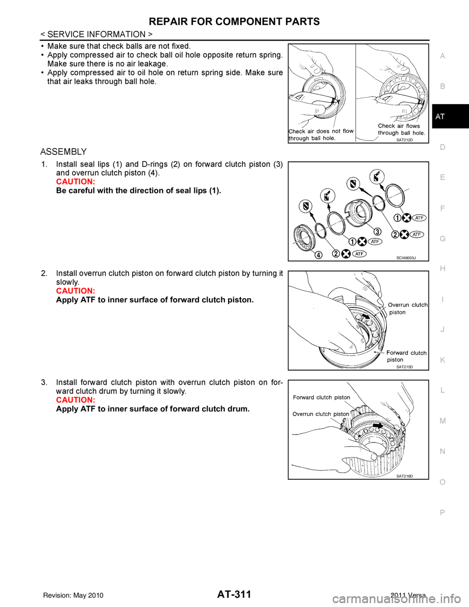
• Make sure that check balls are not fixed.
• Apply compressed air to check ball oil hole opposite return spring. Make sure there is no air leakage.
• Apply compressed air to oil hole on return spring side. Make sure that air leaks through ball hole.
ASSEMBLY
1. Install seal lips (1) and D-rings (2) on forward clutch piston (3) and overrun clutch piston (4).
CAUTION:
Be careful with the direction of seal lips (1).
2. Install overrun clutch piston on forward clutch piston by turning it slowly.
CAUTION:
Apply ATF to inner surface of forward clutch piston.
3. Install forward clutch piston with overrun clutch piston on for- ward clutch drum by turning it slowly.
CAUTION:
Apply ATF to inner surface of forward clutch drum.
SAT212D
SCIA6005J
SAT215D
SAT216D
Revision: May 2010 2011 Versa