2011 NISSAN TIIDA check oil
[x] Cancel search: check oilPage 1229 of 3787
![NISSAN TIIDA 2011 Service Repair Manual CVT-174
< SERVICE INFORMATION >[RE0F08B]
DIFFERENTIAL SIDE OIL SEAL
DIFFERENTIAL SIDE OIL SEAL
Removal and InstallationINFOID:0000000005928975
COMPONENTS
REMOVAL
1. Remove drive shaft assembly. Refer](/manual-img/5/57396/w960_57396-1228.png "NISSAN TIIDA 2011 Service Repair Manual CVT-174
< SERVICE INFORMATION >[RE0F08B]
DIFFERENTIAL SIDE OIL SEAL
DIFFERENTIAL SIDE OIL SEAL
Removal and InstallationINFOID:0000000005928975
COMPONENTS
REMOVAL
1. Remove drive shaft assembly. Refer")
CVT-174
< SERVICE INFORMATION >[RE0F08B]
DIFFERENTIAL SIDE OIL SEAL
DIFFERENTIAL SIDE OIL SEAL
Removal and InstallationINFOID:0000000005928975
COMPONENTS
REMOVAL
1. Remove drive shaft assembly. Refer to
FAX-9.
2. Remove differential side oil seal using a suitable tool. CAUTION:
Do not scratch transaxle case or converter housing.
INSTALLATION
1. Drive the new differential side oil seal into the transaxle caseside (B) and converter housing side (C) until it is flush using
Tool.
Unit: mm (in)
CAUTION:
• Do not reuse differential side oil seals.
• Apply specified NISSAN CVT fluid to side oil seals.
2. Install drive shaft assembly. Refer to FA X - 9
.
3. Check CVT fluid level and leakage. Refer to CVT-14, "
Checking CVT Fluid".
1. CVT2. Differential side oil seal : Apply CVT Fluid NS-2.
WCIA0610E
SCIA2412E
Tool number : — (J-47244)
: ST33400001 (J-47005)
Dimensions (A) 0±0.5 (0 ±0.020)
WCIA0611E
Revision: May 2010 2011 Versa
Page 1231 of 3787
![NISSAN TIIDA 2011 Service Repair Manual CVT-176
< SERVICE INFORMATION >[RE0F08B]
CVT OIL WARMER SYSTEM
When installing water hoses, install them according to the following:
• Insert CVT water hose according to dimension “A” described](/manual-img/5/57396/w960_57396-1230.png "NISSAN TIIDA 2011 Service Repair Manual CVT-176
< SERVICE INFORMATION >[RE0F08B]
CVT OIL WARMER SYSTEM
When installing water hoses, install them according to the following:
• Insert CVT water hose according to dimension “A” described")
CVT-176
< SERVICE INFORMATION >[RE0F08B]
CVT OIL WARMER SYSTEM
When installing water hoses, install them according to the following:
• Insert CVT water hose according to dimension “A” described
below.
• Set hose clamps (1) at the both ends of fluid cooler hose (2) with dimension (A) from the hose edge.
• Hose clamp should not interfere with the bulge.
*: Refer to the illustrations for the specific position of each hose clamp tab.
• The illustrations indicate the view from the hose ends.
• When installing hose clamps the center line of each clamp tab should be positioned as shown.
WATER HOSE : InspectionINFOID:0000000006068648
INSPECTION AFTER INSTALLATION
Start and warm up the engine. Visually check that there is no leakage of engine coolant and CVT fluid.
CVT FLUID COOLER HOSE
CVT water hose (1) Insert side tube (2) Dimension “A”
CVT water hose A Water inlet-outlet
End reaches the spool portion (B)
CVT oil warmer
CVT water hose B CVT oil warmer
CVT water tube
CVT water hose C CVT water tube
Water pump
JSDIA1291ZZ
Dimension (A) : 5 – 7 mm (0.20 – 0.28 in)
SCIA8123E
CVT water hose
Hose end Paint mark
Position of hose clamp*
CVT water hose A Water inlet-outlet side Facing forward A
CVT oil warmer side
Facing forward A
CVT water hose B CVT oil warmer side
Facing to the right of the vehicle B
CVT water tube side Facing forward A
CVT water hose C CVT water tube side
Facing forward A
Water pump side Facing upward C
D: Vehicle front
E : Vehicle upper
JSDIA1292ZZ
Revision: May 2010
2011 Versa
Page 1234 of 3787
![NISSAN TIIDA 2011 Service Repair Manual CVT OIL WARMER SYSTEMCVT-179
< SERVICE INFORMATION > [RE0F08B]
D
E
F
G H
I
J
K L
M A
B
CVT
N
O P
CVT FLUID COOLER HOSE : InspectionINFOID:0000000006068651
INSPECTION AFTER INSTALLATION
Check for CVT f](/manual-img/5/57396/w960_57396-1233.png "NISSAN TIIDA 2011 Service Repair Manual CVT OIL WARMER SYSTEMCVT-179
< SERVICE INFORMATION > [RE0F08B]
D
E
F
G H
I
J
K L
M A
B
CVT
N
O P
CVT FLUID COOLER HOSE : InspectionINFOID:0000000006068651
INSPECTION AFTER INSTALLATION
Check for CVT f")
CVT OIL WARMER SYSTEMCVT-179
< SERVICE INFORMATION > [RE0F08B]
D
E
F
G H
I
J
K L
M A
B
CVT
N
O P
CVT FLUID COOLER HOSE : InspectionINFOID:0000000006068651
INSPECTION AFTER INSTALLATION
Check for CVT fluid leakage and check CVT fluid level. Refer to CVT-14, "Checking CVT Fluid".
CVT OIL WARMER
CVT OIL WARMER : Exploded ViewINFOID:0000000006068652
CVT OIL WARMER : Removal and InstallationINFOID:0000000006068653
REMOVAL
WARNING:
Never remove the radiator cap when the engine is hot. Serious burns could occur from high pressure
coolant escaping from the radiator.
CAUTION:
Perform this step engine is cold.
1. Remove CVT water hose from CVT oil warmer. Refer to CVT-175, "
WATER HOSE : Exploded View".
2. Remove CVT fluid cooler hose from CVT oil warmer. Refer to CVT-177, "
CVT FLUID COOLER HOSE :
Exploded View".
3. Remove CVT oil warmer.
4. Remove bracket.
INSTALLATION
Installation is in the reverse order of removal.
CVT OIL WARMER : InspectionINFOID:0000000006068654
INSPECTION AFTER INSTALLATION
• Check for CVT fluid leakage and check CVT fluid level. Refer to CVT-14, "Checking CVT Fluid".
• Start and warm up the engine. Visually check that there is no leakage of engine coolant and CVT fluid.
1. CVT oil warmer2. Bracket3. Transaxle assembly
Refer to GI-8, "
Component" for symbols in the figure.
JPDIA0725GB
Revision: May 2010 2011 Versa
Page 1236 of 3787
![NISSAN TIIDA 2011 Service Repair Manual TRANSAXLE ASSEMBLYCVT-181
< SERVICE INFORMATION > [RE0F08B]
D
E
F
G H
I
J
K L
M A
B
CVT
N
O P
2. Disconnect the primary speed sensor (A) and the secondary
speed sensor connector (B) and CVT unit conn](/manual-img/5/57396/w960_57396-1235.png "NISSAN TIIDA 2011 Service Repair Manual TRANSAXLE ASSEMBLYCVT-181
< SERVICE INFORMATION > [RE0F08B]
D
E
F
G H
I
J
K L
M A
B
CVT
N
O P
2. Disconnect the primary speed sensor (A) and the secondary
speed sensor connector (B) and CVT unit conn")
TRANSAXLE ASSEMBLYCVT-181
< SERVICE INFORMATION > [RE0F08B]
D
E
F
G H
I
J
K L
M A
B
CVT
N
O P
2. Disconnect the primary speed sensor (A) and the secondary
speed sensor connector (B) and CVT unit connector (C). Refer
to CVT-9, "
Removal and Installation Procedure for CVT Unit
Connector".
3. Remove the harness from the transaxle.
4. Remove the four drive plate to torque converter nuts. NOTE:
Rotate the crankshaft clockwise as viewed from front of engine
for access to drive plate to torque converter nuts.
5. Put matching marks on the drive plate and torque converter alignment stud. CAUTION:
For matching marks, use paint. Never dama ge the drive plate or torque converter.
6. Remove the transaxle to engine and engine to transaxle bolts.
7. Separate the transaxle from the engine.
8. If necessary, remove the following from the transaxle: • CVT fluid charging pipe
• Engine mounting bracket (LH)
• Fluid cooler tubes
• Air breather hose
• Any necessary brackets
INSTALLATION
Installation is in the reverse order of removal.
CAUTION:
• When replacing an engine or transmission you must make sure any dowels are installed correctlyduring re-assembly.
• Improper alignment caused by missing dowels may cause vibration, oil leaks or breakage of drive train components.
• Do not reuse O-rings and copper washers.
• When turning crankshaft, turn it clockwise as viewed from the front of the engine.
• When tightening the nuts for the torque converter while securing the crankshaft pulley bolt, be sure
to confirm the tightening torque of the crankshaft pulley bolt. Refer to EM-159
.
• After converter is installed to drive plate, ro tate crankshaft several turns to check that transaxle
rotates freely without binding.
AWDIA0661GB
WCIA0616E
Revision: May 2010 2011 Versa
Page 1253 of 3787

DI-14
< SERVICE INFORMATION >
COMBINATION METERS
NOTE:
Some items are not available due to vehicle specification.
*: The monitor will indicate “OFF” even though the brake warning lamp is on if either of the following conditions exist.
• The parking brake is engaged
• The brake fluid level is low
Trouble DiagnosisINFOID:0000000005929168
HOW TO PERFORM TROUBLE DIAGNOSIS
1. Confirm the symptom or customer complaint.
2. Perform preliminary check. Refer to "PRELIMINARY CHECK" .
3. According to the symptom chart, repair or replace the cause of the malfunction. Refer to DI-15, "
Symptom
Chart" .
4. Does the meter operate normally? If so, GO TO 5. If not, GO TO 2.
5. Inspection End.
PRELIMINARY CHECK
1.CHECK SELF-DIAGNOSIS OPERAT ION OF COMBINATION METER
Perform self-diagnosis of combination meter. Refer to DI-11, "
Self-Diagnosis Mode of Combination Meter" .
Does self
-diagnosis mode operate?
TURN IND [ON/OFF] X Indicates [ON/OFF] condition of turn indicator.
OIL W/L [ON/OFF] X Indicates [ON/OFF] condition of oil pressure warning lamp.
VDC/TCS IND [ON/OFF] X Indicates [ON/OFF] condition of VDC OFF indicator lamp.
ABS W/L [ON/OFF] X Indicates [ON/OFF] condition of ABS warning lamp.
SLIP IND [ON/OFF] X Indicates [ON/OFF] condition of SLIP indicator lamp.
BRAKE W/L [ON/OFF] X Indicates [ON/OFF] condition of brake warning lamp.*
KEY G/Y W/L [ON/OFF] X Indicates [ON/OFF] condition of KEY warning lamp (green).
KEY R W/L [ON/OFF] X Indicates [ON/OFF] condition of KEY warning lamp (red).
KEY KNOB W/L [ON/OFF] X Indicates [ON/OFF] condition of LOCK warning lamp.
PNP P SW [ON/OFF] XX Indicates [ON/OFF] condition of inhibitor P switch.
PNP N SW [ON/OFF] XX Indicates [ON/OFF] condition of inhibitor N switch.
O/D OFF SW [ON/OFF] X Indicates [ON/OFF] condition of O/D OFF switch.
BRAKE SW [ON/OFF] X Indicates [ON/OFF] condition of parking brake switch.
P RANGE IND [ON/OFF] XXIndicates [ON/OFF] condition of A/T or CVT shift P range indi-
cator.
R RANGE IND [ON/OFF] XXIndicates [ON/OFF] condition of A/T or CVT shift R range indi-
cator.
N RANGE IND [ON/OFF] XXIndicates [ON/OFF] condition of A/T or CVT shift N range indi-
cator.
D RANGE IND [ON/OFF] XXIndicates [ON/OFF] condition of A/T or CVT shift D range indi-
cator.
2 RANGE IND [ON/OFF] XX Indicates [ON/OFF] condition of A/T shift 2 range indicator.
L RANGE IND [ON/OFF] XX Indicates [ON/OFF] condition of CVT shift L range indicator.
1 RANGE IND [ON/OFF] XX Indicates [ON/OFF] condition of A/T shift 1 range indicator.
CRUISE IND [ON/OFF] X Indicates [ON/OFF] condition of CRUISE indicator.
SET IND [ON/OFF] X Indicates [ON/OFF] condition of SET indicator.
O/D OFF W/L [ON/OFF] X Indicates [ON/OFF] condition of O/D OFF indicator lamp.
EPS W/L [ON/OFF] X Indicates [ON/OFF] condition of EPS warning lamp.
Display item [Unit]
MAIN
SIGNALS SELECTION
FROM MENU Contents
Revision: May 2010
2011 Versa
Page 1269 of 3787
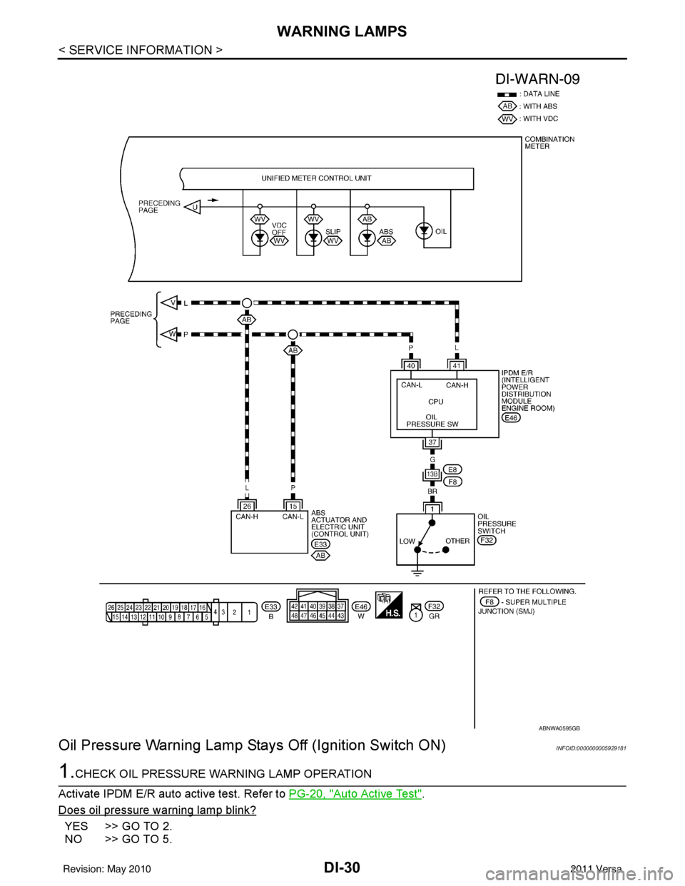
DI-30
< SERVICE INFORMATION >
WARNING LAMPS
Oil Pressure Warning Lamp Stays Off (Ignition Switch ON)
INFOID:0000000005929181
1.CHECK OIL PRESSURE WARNING LAMP OPERATION
Activate IPDM E/R auto active test. Refer to PG-20, "
Auto Active Test".
Does oil pressure warning lamp blink?
YES >> GO TO 2.
NO >> GO TO 5.
ABNWA0595GB
Revision: May 2010 2011 Versa
Page 1270 of 3787
WARNING LAMPSDI-31
< SERVICE INFORMATION >
C
DE
F
G H
I
J
L
M A
B
DI
N
O P
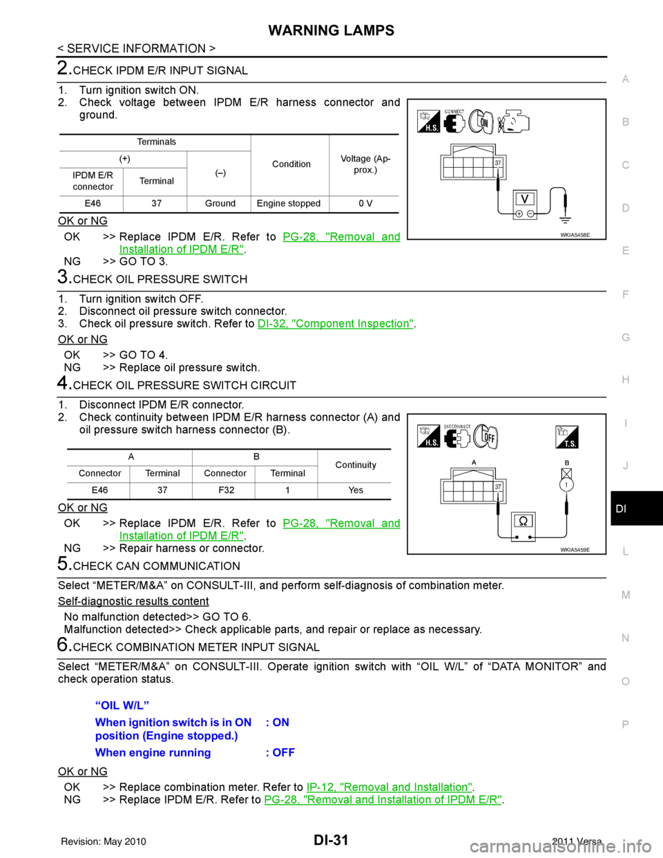
2.CHECK IPDM E/R INPUT SIGNAL
1. Turn ignition switch ON.
2. Check voltage between IPDM E/R harness connector and ground.
OK or NG
OK >> Replace IPDM E/R. Refer to PG-28, "Removal and
Installation of IPDM E/R".
NG >> GO TO 3.
3.CHECK OIL PRESSURE SWITCH
1. Turn ignition switch OFF.
2. Disconnect oil pressure switch connector.
3. Check oil pressure switch. Refer to DI-32, "
Component Inspection".
OK or NG
OK >> GO TO 4.
NG >> Replace oil pressure switch.
4.CHECK OIL PRESSURE SWITCH CIRCUIT
1. Disconnect IPDM E/R connector.
2. Check continuity between IPDM E/R harness connector (A) and oil pressure switch harness connector (B).
OK or NG
OK >> Replace IPDM E/R. Refer to PG-28, "Removal and
Installation of IPDM E/R".
NG >> Repair harness or connector.
5.CHECK CAN COMMUNICATION
Select “METER/M&A” on CONSULT-III, and per form self-diagnosis of combination meter.
Self
-diagnostic results content
No malfunction detected>> GO TO 6.
Malfunction detected>> Check applicable parts, and repair or replace as necessary.
6.CHECK COMBINATION METER INPUT SIGNAL
Select “METER/M&A” on CONS ULT-III. Operate ignition switch with “OIL W/L” of “DATA MONITOR” and
check operation status.
OK or NG
OK >> Replace combination meter. Refer to IP-12, "Removal and Installation".
NG >> Replace IPDM E/R. Refer to PG-28, "
Removal and Installation of IPDM E/R".
Te r m i n a l s
ConditionVoltage (Ap-
prox.)
(+)
(–)
IPDM E/R
connector Te r m i n a l
E46 37 Ground Engine stopped 0 V
WKIA5458E
AB
Continuity
Connector Terminal Connector Terminal
E46 37 F32 1 Yes
WKIA5459E
“OIL W/L”
When ignition switch is in ON
position (Engine stopped.) : ON
When engine running : OFF
Revision: May 2010 2011 Versa
Page 1271 of 3787
DI-32
< SERVICE INFORMATION >
WARNING LAMPS
Oil Pressure Warning Lamp Does Not Turn Off (Oil Pressure Is Normal)
INFOID:0000000005929182
NOTE:
For oil pressure inspection, refer to LU-17, "
Inspection".
1.CHECK OIL PRESSURE WARNING LAMP OPERATION
Activate IPDM E/R auto active test. Refer to PG-20, "
Auto Active Test".
Does oil pressure warning lamp blink?
YES >> GO TO 2.
NO >> GO TO 5.
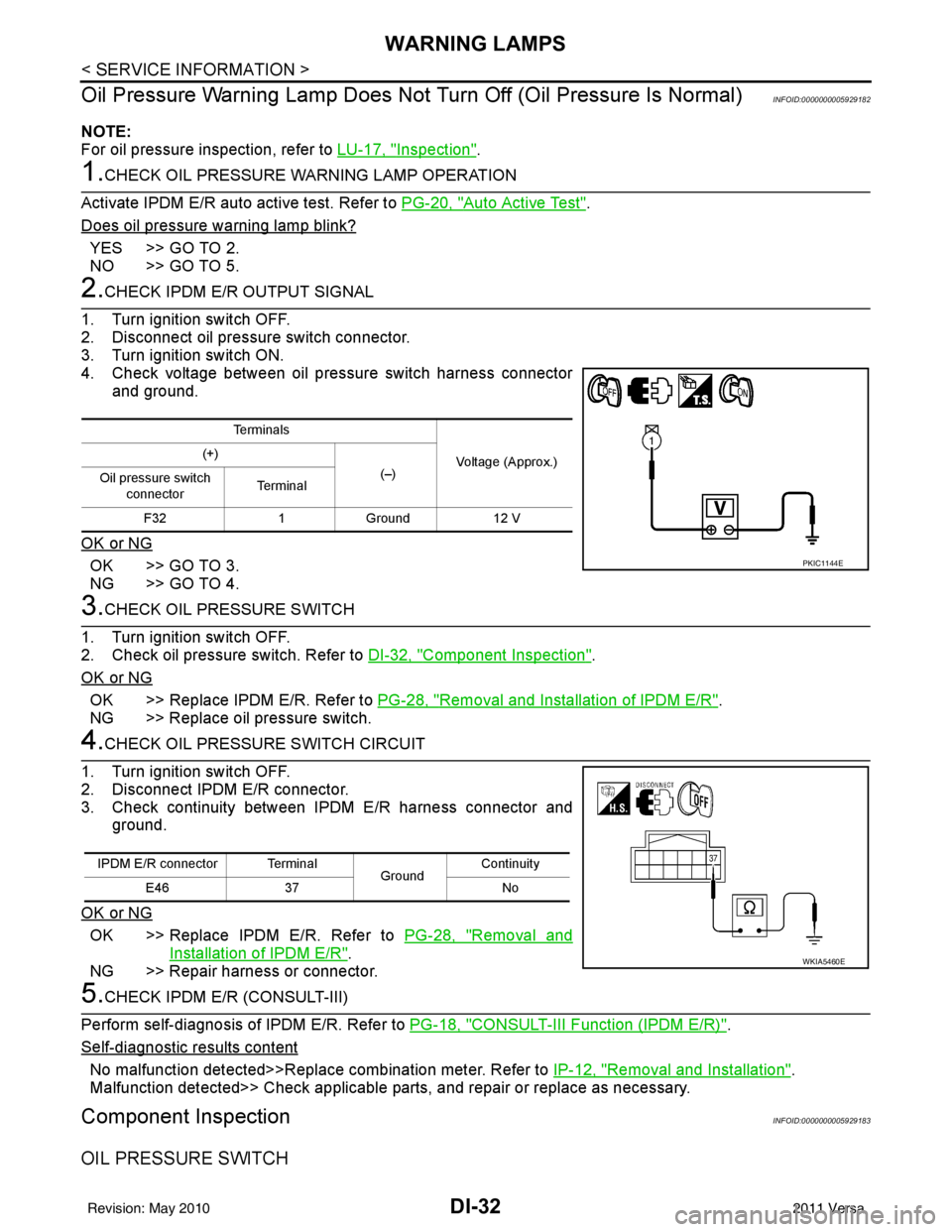
2.CHECK IPDM E/R OUTPUT SIGNAL
1. Turn ignition switch OFF.
2. Disconnect oil pressure switch connector.
3. Turn ignition switch ON.
4. Check voltage between oil pressure switch harness connector and ground.
OK or NG
OK >> GO TO 3.
NG >> GO TO 4.
3.CHECK OIL PRESSURE SWITCH
1. Turn ignition switch OFF.
2. Check oil pressure switch. Refer to DI-32, "
Component Inspection".
OK or NG
OK >> Replace IPDM E/R. Refer to PG-28, "Removal and Installation of IPDM E/R".
NG >> Replace oil pressure switch.
4.CHECK OIL PRESSURE SWITCH CIRCUIT
1. Turn ignition switch OFF.
2. Disconnect IPDM E/R connector.
3. Check continuity between IPDM E/R harness connector and ground.
OK or NG
OK >> Replace IPDM E/R. Refer to PG-28, "Removal and
Installation of IPDM E/R".
NG >> Repair harness or connector.
5.CHECK IPDM E/R (CONSULT-III)
Perform self-diagnosis of IPDM E/R. Refer to PG-18, "
CONSULT-III Function (IPDM E/R)".
Self
-diagnostic results content
No malfunction detected>>Replace combination meter. Refer to IP-12, "Removal and Installation".
Malfunction detected>> Check applicable parts, and repair or replace as necessary.
Component InspectionINFOID:0000000005929183
OIL PRESSURE SWITCH
Te r m i n a l s
Voltage (Approx.)
(+)
(–)
Oil pressure switch
connector Te r m i n a l
F32 1Ground 12 V
PKIC1144E
IPDM E/R connector Terminal
GroundContinuity
E46 37 No
WKIA5460E
Revision: May 2010 2011 Versa