2011 NISSAN TIIDA display
[x] Cancel search: displayPage 219 of 3787
AT-202
< SERVICE INFORMATION >
TROUBLE DIAGNOSIS FOR SYMPTOMS
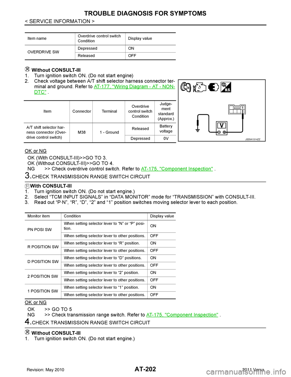
Without CONSULT-III
1. Turn ignition switch ON. (Do not start engine)
2. Check voltage between A/T shift selector harness connector ter-
minal and ground. Refer to AT-177, "
Wiring Diagram - AT - NON-
DTC" .
OK or NG
OK (With CONSULT-III)>>GO TO 3.
OK (Without CONSULT-III)>>GO TO 4.
NG >> Check overdrive control switch. Refer to AT-175, "
Component Inspection" .
3.CHECK TRANSMISSION RANGE SWITCH CIRCUIT
With CONSULT-III
1. Turn ignition switch ON. (Do not start engine.)
2. Select “TCM INPUT SIGNALS” in “DATA MONITOR” mode for “TRANSMISSION” with CONSULT-III.
3. Read out “P·N”, “R”, “D”, “2” and “1” position switches moving selector lever to each position.
OK or NG
OK >> GO TO 5
NG >> Check transmission range switch. Refer to AT-175, "
Component Inspection" .
4.CHECK TRANSMISSION RANGE SWITCH CIRCUIT
Without CONSULT-III
1. Turn ignition switch ON. (Do not start engine.)
Item name Overdrive control switch
ConditionDisplay value
OVERDRIVE SW Depressed
ON
Released OFF
ItemConnector Terminal Overdrive
control switch
Condition Judge-
ment
standard
(Approx.)
A/T shift selector har-
ness connector (Over-
drive control switch) M38 1 - Ground
Released
Battery
voltage
Depressed 0V
JSDIA1514ZZ
Monitor item Condition Display value
PN POSI SW When setting selector le
ver to “N” or “P” posi-
tion. ON
When setting selector lever to other positions. OFF
R POSITION SW When setting selector lever to “R” position. ON
When setting selector lever to other positions. OFF
D POSITION SW When setting selector lever to “D” positions. ON
When setting selector lever to other positions. OFF
2 POSITION SW When setting selector lever to “2” position. ON
When setting selector lever to other positions. OFF
1 POSITION SW When setting selector lever to “1” position. ON
When setting selector lever to other positions. OFF
Revision: May 2010
2011 Versa
Page 416 of 3787
![NISSAN TIIDA 2011 Service Repair Manual AUDIOAV-19
< SERVICE INFORMATION > [AUDIO WITHOUT NAVIGATION]
C
D
E
F
G H
I
J
L
M A
B
AV
N
O P
Terminal and Reference Value for IPod AdapterINFOID:0000000005931283
Te r m i n a l
(Wire color) Descrip](/manual-img/5/57396/w960_57396-415.png "NISSAN TIIDA 2011 Service Repair Manual AUDIOAV-19
< SERVICE INFORMATION > [AUDIO WITHOUT NAVIGATION]
C
D
E
F
G H
I
J
L
M A
B
AV
N
O P
Terminal and Reference Value for IPod AdapterINFOID:0000000005931283
Te r m i n a l
(Wire color) Descrip")
AUDIOAV-19
< SERVICE INFORMATION > [AUDIO WITHOUT NAVIGATION]
C
D
E
F
G H
I
J
L
M A
B
AV
N
O P
Terminal and Reference Value for IPod AdapterINFOID:0000000005931283
Te r m i n a l
(Wire color) Description
ConditionReference value
(Approx.)
+ – Signal nameInput/
Output
1
(R) 13
(W) iPod® sound signal LH Output Ignition
switch ON When iPod® mode is se-
lected.
2
(B) 14
(G) iPod® sound signal RH Output Ignition
switch ON When iPod® mode is se-
lected.
3
(Y) Ground ACC power supply
InputIgnition
switch ACC —
Battery voltage
4
(P) —AV communication signal
(L) Input/
Output ——
—
5
(BR) Ground Battery power supply Input Ignition
switch OFF —
Battery voltage
6
(G) 7
(Y) iPod® USD signal
—Ignition
switch
ON ——
8
(W) Ground iPod® battery charge Output Ignition
switch ON Connected to iPod®.
Battery voltage
9
(SB) Ground Communication signal
(iPod® adapter
→iPod®) OutputIgnition
switch ON The wave pattern is dis-
played just after iPod® con-
nection.
NOTE:
After the wave pattern display,
the value continues Approx 3.3V
10
(V) Ground Communication signal
(iPod®
→iPod® adapter) InputIgnition
switch ON Connected to iPod®.
11
(GR) Ground ACCESSORY-IDENTIFY — Ignition
switch
ON Co
nn
ec
ted to iPod®.
0V
SKIB3609E
SKIB3609E
JPNIA0462GB
JPNIA0462GB
Revision: May 2010 2011 Versa
Page 451 of 3787
![NISSAN TIIDA 2011 Service Repair Manual AV-54
< SERVICE INFORMATION >[AUDIO WITH NAVIGATION]
AUDIO
System Description
INFOID:0000000006216702
AUDIO SYSTEM
Refer to Owners Manual for audio system operating instructions.
Navigation is built](/manual-img/5/57396/w960_57396-450.png "NISSAN TIIDA 2011 Service Repair Manual AV-54
< SERVICE INFORMATION >[AUDIO WITH NAVIGATION]
AUDIO
System Description
INFOID:0000000006216702
AUDIO SYSTEM
Refer to Owners Manual for audio system operating instructions.
Navigation is built")
AV-54
< SERVICE INFORMATION >[AUDIO WITH NAVIGATION]
AUDIO
System Description
INFOID:0000000006216702
AUDIO SYSTEM
Refer to Owner's Manual for audio system operating instructions.
Navigation is built into AV control unit.
This navigation has the following functions.
• Full support for playback of music from iPod
® and USB device.
• High resolution full color touch panel 5 “WQVGA” display.
• FM/AM twin digital tuner.
• USB mass storage.
•XM traffic.
• POI Support is included. User POI download.
Power is supplied at all times
• through 20A fuse (No. 27, located in the fuse and fusible link box)
• to AV control unit terminal 19.
With the ignition switch in the ACC or ON position, power is supplied
• through 10A fuse [No. 20, located in the fuse block (J/B)]
• to AV control unit terminal 7.
Ground is supplied to
• to AV control unit terminals 20 and 32
• through grounds M57 and M61.
Then audio signals are supplied
• through AV control unit terminals 2, 3, 4, 5, 11, 12, 13 and 14
• to terminals + and - of front door speaker LH and RH
• to terminals + and - of front tweeter LH and RH and
• to terminals + and - of rear door speaker LH and RH.
STEERING WHEEL AUDIO CONTROL SWITCHES
When one of steering wheel audio control switches is pus hed, the resistance in steering switch circuit changes
depending on which button is pushed.
AWNIA2215GB
Revision: May 2010 2011 Versa
Page 460 of 3787
![NISSAN TIIDA 2011 Service Repair Manual AUDIOAV-63
< SERVICE INFORMATION > [AUDIO WITH NAVIGATION]
C
D
E
F
G H
I
J
L
M A
B
AV
N
O P
On-Board DiagnosisINFOID:0000000006216707
METHOD OF STARTING
1. Start the engine.
2. Turn OFF audio.
3. Whil](/manual-img/5/57396/w960_57396-459.png "NISSAN TIIDA 2011 Service Repair Manual AUDIOAV-63
< SERVICE INFORMATION > [AUDIO WITH NAVIGATION]
C
D
E
F
G H
I
J
L
M A
B
AV
N
O P
On-Board DiagnosisINFOID:0000000006216707
METHOD OF STARTING
1. Start the engine.
2. Turn OFF audio.
3. Whil")
AUDIOAV-63
< SERVICE INFORMATION > [AUDIO WITH NAVIGATION]
C
D
E
F
G H
I
J
L
M A
B
AV
N
O P
On-Board DiagnosisINFOID:0000000006216707
METHOD OF STARTING
1. Start the engine.
2. Turn OFF audio.
3. While pressing the “SET UP” switch, turn the MENU dial coun- terclockwise 3 clicks or more first, then clockwise and counter-
clockwise 3 clicks or more, respectively. (After the diagnosis
mode starts, the initial screen of the diagnosis mode appears.)
• On-board diagnosis can be performed in the service test mode.
• On-board diagnosis checks that t he system can be operated normally.
Service test mode
46 (L) —AUX sound
signal LH—— —
——
47 (W) — USB D- — — —— —
48 (GR) — AUX sound
signal RH—— —
——
49 (G) — USB D+ — — —— —
50 (BR) — AUX sound
signal
ground—— —
——
51 (R) — USB V BUS
signal—— —
——
53 (GR) — SHIELD — — —— —
54 — Satellite an-
tenna signal
—— —
——
55 — GPS anten-
na signal—— —
——
56 — SHIELD — — —— —
57 — Antenna on
signal—— —
——
58 — Main anten-
na signal
—— —
——
Te r m i n a l
(Wire color) ItemSignal
input/
output Condition
Reference value
(Approx.) Example of symp-
tom
+– Ignition
switch Operation
JSNIA2456ZZ
Mode
ItemContent
Service version —The version data of the parts is shown
displayed.
Revision: May 2010
2011 Versa
Page 461 of 3787
![NISSAN TIIDA 2011 Service Repair Manual AV-64
< SERVICE INFORMATION >[AUDIO WITH NAVIGATION]
AUDIO
RadioFM monitor
—The Change Mediator monitors the dy-
namic values of the current tuner. If the
band is switched within the radio mon-
ito](/manual-img/5/57396/w960_57396-460.png "NISSAN TIIDA 2011 Service Repair Manual AV-64
< SERVICE INFORMATION >[AUDIO WITH NAVIGATION]
AUDIO
RadioFM monitor
—The Change Mediator monitors the dy-
namic values of the current tuner. If the
band is switched within the radio mon-
ito")
AV-64
< SERVICE INFORMATION >[AUDIO WITH NAVIGATION]
AUDIO
RadioFM monitor
—The Change Mediator monitors the dy-
namic values of the current tuner. If the
band is switched within the radio mon-
itor context, the active monitor is
switched as well.
AM monitor
—
XM monitor —The version data is displayed.
XM functions • Clear XM Chipset NVM
• Reset all XM settings
• XM CBM debug mode ON/OFF
• External Diag mode ON/OFF The current system status is dis-
played.
User Configuration Touch Display Calibration —The function allows connection of the
position detection accuracy of the
touch panel.
Mode
ItemContent
Revision: May 2010 2011 Versa
Page 462 of 3787
![NISSAN TIIDA 2011 Service Repair Manual AUDIOAV-65
< SERVICE INFORMATION > [AUDIO WITH NAVIGATION]
C
D
E
F
G H
I
J
L
M A
B
AV
N
O P
System state Running system status
• SD card slot Access
• Power Supply
• Speed Signal
• Direction](/manual-img/5/57396/w960_57396-461.png "NISSAN TIIDA 2011 Service Repair Manual AUDIOAV-65
< SERVICE INFORMATION > [AUDIO WITH NAVIGATION]
C
D
E
F
G H
I
J
L
M A
B
AV
N
O P
System state Running system status
• SD card slot Access
• Power Supply
• Speed Signal
• Direction")
AUDIOAV-65
< SERVICE INFORMATION > [AUDIO WITH NAVIGATION]
C
D
E
F
G H
I
J
L
M A
B
AV
N
O P
System state Running system status
• SD card slot Access
• Power Supply
• Speed Signal
• Direction Signal
• Illumination Signal
• GPS Antenna
• EXT. Phone Sig
• Microphone Current
• Radio Antenna
• USB Device
•iPod
® firmware version
• Steering wheel X11C The current system status is dis-
played.
System history •Bluetooth
® Module - Sub-Unit
Connection Malfunction
• SD-card Slot - Sub-Unit Connec- tion Malfunction
• Programming Error
• Radio-Antenna Circuit Malfunc- tion
• FM-Antenna 1 Connection Mal- function
• Satellite Antenna Connection
Failure
• GPS Antenna Circuit Malfunc- tion
• CD-Drive Mechanical Malfunc- tion
• CD Read Malfunction
• Power Supply voltage: Lower
Limit Exceeded
• Power Supply voltage: Upper
Limit Exceeded
• Reduced system Functionality due to over temperature
• Display switched OFF due to over temperature
• SD card removed without being de-mounted
• Code plug missing The history of the system status is re-
ported in the re
port memory, dis-
played.
Speaker test 100Hz —This activates a sequence of test tone
outputs to the four speaker lines one
after the other for 1 second.
The frequency can be chosen by user
selection (100Hz and 4KHz).
Speaker test 4KHz
Display test —This provides a test sequence where
test displays (plain colored display:
e.g. white, black, red, blue, green) are
shown one after the other.
The respective color is shown for an
indicated period of time (parameter).
After the display test, the design of the
display previously available is stored.
While the screen shows a plain col-
ored display, a pixel malfunction may
be detected.
Mode
ItemContent
Revision: May 2010 2011 Versa
Page 463 of 3787
![NISSAN TIIDA 2011 Service Repair Manual AV-66
< SERVICE INFORMATION >[AUDIO WITH NAVIGATION]
AUDIO
END ON-BOARD DIAGNOSIS
Turn OFF ignition switch.
Noise InspectionINFOID:0000000005931317
The vehicle itself can be a source of noise if noise](/manual-img/5/57396/w960_57396-462.png "NISSAN TIIDA 2011 Service Repair Manual AV-66
< SERVICE INFORMATION >[AUDIO WITH NAVIGATION]
AUDIO
END ON-BOARD DIAGNOSIS
Turn OFF ignition switch.
Noise InspectionINFOID:0000000005931317
The vehicle itself can be a source of noise if noise")
AV-66
< SERVICE INFORMATION >[AUDIO WITH NAVIGATION]
AUDIO
END ON-BOARD DIAGNOSIS
Turn OFF ignition switch.
Noise InspectionINFOID:0000000005931317
The vehicle itself can be a source of noise if noise
prevention parts or electrical equipment is malfunctioning.
Check if noise is caused and/or changed by engine speed, ignition switch turned to each position, and opera-
tion of each piece of electrical equipment, and determine the cause.
NOTE:
The source of the noise can be found easily by listening to the noise while removing the fuses of electrical
components, one by one.
TYPE OF NOISE AND POSSIBLE CAUSE
Symptom ChartINFOID:0000000006216708
MALFUNCTION WITH NAVIGATION
System configuration • 8 pulses speed
• Clock ON/OFF
• Equalizer setup X11C
• RF tuning
• Antenna type
• Sound system
• Sub Out: Code
• Steering wheel The device is configured by a connect-
ed hardware circuit.
The parameter is
influenced.
Self test •Bluetooth
® module Access Mal-
function
• SD-card Access Malfunction
• Radio-Antenna Circuit Malfunc-
tion
• GPS Antenna Circuit Malfunc-
tion
• Microphone Circuit Malfunction A system self test is executed: the re-
sult is stored into
the error memory
which is shown afterwards as a list of
codes of the detected malfunctions.
Mode
ItemContent
Occurrence condition Possible cause
Occurs only when engine is ON. A continuous growling noise occurs. The speed of
the noise varies with changes in the engine speed.
Ignition components
A whistling noise occurs while the engine speed is
high. A booming noise occurs while the engine is
running and the lighting switch is ON. Generator
Noise only occurs when various
electrical components are oper-
ating. A cracking or snapping sound occurs with the op-
eration of various switches.
Relay malfunction, radio malfunction
The noise occurs when various motors are operat-
ing. • Motor case ground
• Motor
The noise occurs constantly, not just under certain conditions. • Rear defogger coil malfunction
• Open circuit in printed heater
A cracking or snapping sound occurs while the vehicle is being driven, especially when
it is vibrating excessively. • Ground wire of body parts.
• Ground due to improper part installation
• Wiring connections or a short circuit
Symptoms
Check itemsProbable malfunction location / Action to
take
Display does not turn ON. All switches cannot be operated.
AV control unit power supply and ground
circuit. Refer to
AV- 6 9
.
All switches can be operated. AV control unit. Refer to AV- 6 9
.
Revision: May 2010 2011 Versa
Page 464 of 3787
![NISSAN TIIDA 2011 Service Repair Manual AUDIOAV-67
< SERVICE INFORMATION > [AUDIO WITH NAVIGATION]
C
D
E
F
G H
I
J
L
M A
B
AV
N
O P
MALFUNCTION WITH AUDIO
• The majority of the audio malfunctions are the result of outside causes (Malfunct](/manual-img/5/57396/w960_57396-463.png "NISSAN TIIDA 2011 Service Repair Manual AUDIOAV-67
< SERVICE INFORMATION > [AUDIO WITH NAVIGATION]
C
D
E
F
G H
I
J
L
M A
B
AV
N
O P
MALFUNCTION WITH AUDIO
• The majority of the audio malfunctions are the result of outside causes (Malfunct")
AUDIOAV-67
< SERVICE INFORMATION > [AUDIO WITH NAVIGATION]
C
D
E
F
G H
I
J
L
M A
B
AV
N
O P
MALFUNCTION WITH AUDIO
• The majority of the audio malfunctions are the result of outside causes (Malfunction CD, electromagnetic interference, etc.). Check the sympt oms below to diagnose the malfunction.
• The vehicle itself can be a source of noise if noise prevention parts or electrical equipment is malfunctioning.
Check if noise is caused and/or changed by engine speed, ignition switch turned to each position, and oper-
ation of each piece of electrical equipment, and then determine the cause.
NOTE:
• CD-R is not guaranteed to play because they can contain compressed audio (MP3, WMA) or could be incorrectly mastered by the customer on a computer.
• Check if the CDs have the Compact Disc logo. If not, the disc is not mastered to the “red book” Compact
Disc standard and may not play.
All switches cannot be operated. Display does not turn ON.
AV control unit power supply and ground
circuit. Refer to
AV- 6 9.
Display turn ON. AV control unit. Refer to AV- 6 9
.
Only specified switch cannot be
operated. –
AV control unit. Refer to AV- 6 9
.
Voice guidance is not heard. Audio sound is normal. AV control unit. Refer to AV- 6 9
.
Display does not dim. Check “Illumination
Signal” in “SERVICE
SYSTEM STATUS”,
“SERVICE MENU”. “Illumination Signal” reaches
100% when the lighting
switch is ON.
AV control unit. Refer to
AV- 7 3
.
“Illumination Signal” does not
reach 100% when the lighting
switch is ON. Illumination signal circuit. Refer to
LT-
109.
Vehicle icon does not move. Check “Speed Signal”
in “SERVICE SYSTEM
STATUS”, “SERVICE
MENU”. A value of “Speed Signal”
changes according to vehicle
speeds.
AV control unit. Refer to
AV- 7 3
.
A value of “Speed Signal”
does not change according to
vehicle speeds. Vehicle speed signal circuit. Refer to
DI-
16.
Map matching is not complete
GPS icon is not displayed Check “GPS Antenna”
in “SERVICE SYSTEM
SELF TEST”, “SER-
VICE MENU”. “Connected” is displayed for
“GPS Antenna”.
AV control unit. Refer to
AV- 7 3
.
“Connected” is not displayed
for “GPS Antenna”. GPS antenna. Refer to
AV- 9 3
.
Traffic information (XM Traffic) is
not received. Radio broadcasts are received.
AV control unit. Refer to AV- 7 3
.
Radio broadcasts are not received. • Radio antenna. Refer to
AV- 9 1
.
• Antenna feeder. Refer to AV- 9 1
.
Symptoms
Check itemsProbable malfunction location / Action to
take
Symptom Probable malfunction location
Audio system does not work normally. • AV control unit power supply and ground circuit. Refer to
AV- 6 9
.
• AV control unit. Refer to AV- 7 3
.
Audio steering wheel switch does not operate proper-
ly. • Remote control signal circuit between steering switch and AV control unit.
Refer to AV- 6 9
.
• Steering wheel audio control switch. Refer to AV- 7 3
.
• AV control unit. Refer to AV- 7 3
.
No sound can be heard from any speakers. • Speaker circuit shorted to ground. Refer to
AV- 5 6
.
• AV control unit. Refer to AV- 7 3
.
No sound can be heard from front speakers. • Audio signal circuit between AV control unit and front speakers. Refer to
AV- 7 0
.
• Front speaker. Refer to AV- 7 3
.
• Front tweeter. Refer to AV- 7 3
.
• AV control unit. Refer to AV- 7 3
.
Revision: May 2010 2011 Versa