Page 264 of 3787
OVERHAULAT-247
< SERVICE INFORMATION >
DE
F
G H
I
J
K L
M A
B
AT
N
O P
1. Retaining plate 2. Driven plate3. Dish plate
4. Snap ring 5. Spring retainer assembly6. Reverse clutch piston
7. Seal lip 8. D-ring9. Reverse clutch drum
10. Thrust washer 11. Reverse clutch assembly 12. Drive plate
13. Snap ring 14. Needle bearing15. Front sun gear
16. Needle bearing 17. High clutch hub18. Snap ring
SCIA7991E
Revision: May 2010 2011 Versa
Page 265 of 3787

AT-248
< SERVICE INFORMATION >
OVERHAUL
19. Retaining plate20. Drive plate21. Snap ring
22. Cancel cover 23. Spring retainer assembly 24. High clutch piston
25. Input shaft assembly (high clutch drum) 26. Needle bearing
27. High clutch assembly
28. Bearing race 29. Seal ring30. Driven plate
31. Needle bearing 32. Needle bearing33. Overrun clutch hub
34. End bearing 35. Forward clutch hub 36. Needle bearing
37. Rear planetary carrier 38. Rear sun gear 39. Front planetary carrier
40. Low one-way clutch 41. Snap ring42. Needle bearing
43. Needle bearing 44. Rear internal gear 45. Thrust washer
46. Forward one-way clutch 47. Thrust washer48. Thrust washer
49. Forward clutch drum 50. Seal lip51. Seal lip
52. Overrun clutch piston 53. Spring retainer assembly54. Snap ring
55. Dish plate 56. Driven plate57. Retaining plate
58. Snap ring 59. Dish plate60. Driven plate
61. Retaining plate 62. Snap ring63. Forward clutch assembly and over-
run clutch assembly
64. Drive plate 65. Drive plate 66. D-ring
67. Forward clutch piston 68. D-ring 69. Needle bearing
70. Seal lip 71. Driven plate 72. Snap ring
73. Low & reverse brake assembly 74. Retaining plate 75. Drive plate
76. Retaining plate 77. Dish plate78. Driven plate
79. Snap ring 80. Spring retainer assembly 81. Low & reverse brake piston
82. D-ring
Revision: May 2010 2011 Versa
Page 277 of 3787

AT-260
< SERVICE INFORMATION >
DISASSEMBLY
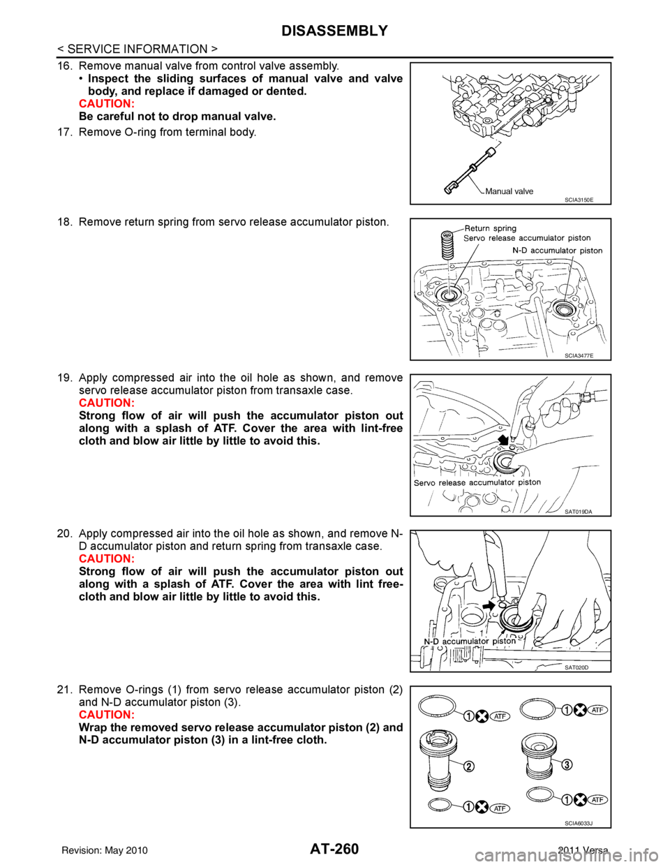
16. Remove manual valve from control valve assembly.•Inspect the sliding surfaces of manual valve and valve
body, and replace if damaged or dented.
CAUTION:
Be careful not to drop manual valve.
17. Remove O-ring from terminal body.
18. Remove return spring from servo release accumulator piston.
19. Apply compressed air into the oil hole as shown, and remove servo release accumulator piston from transaxle case.
CAUTION:
Strong flow of air will push the accumulator piston out
along with a splash of ATF. Cover the area with lint-free
cloth and blow air little by little to avoid this.
20. Apply compressed air into the oil hole as shown, and remove N- D accumulator piston and return spring from transaxle case.
CAUTION:
Strong flow of air will push the accumulator piston out
along with a splash of ATF. Cover the area with lint free-
cloth and blow air little by little to avoid this.
21. Remove O-rings (1) from servo release accumulator piston (2) and N-D accumulator piston (3).
CAUTION:
Wrap the removed servo release accumulator piston (2) and
N-D accumulator piston (3) in a lint-free cloth.
SCIA3150E
SCIA3477E
SAT019DA
SAT020D
SCIA6033J
Revision: May 2010 2011 Versa
Page 283 of 3787
AT-266
< SERVICE INFORMATION >
DISASSEMBLY
b. Remove input shaft assembly (high clutch assembly) (1) fromreverse clutch assembly (2).
c. Remove needle bearing (1) from input shaft assembly (high clutch drum) (2).
•Inspect needle bearing (1) and input shaft assembly (high
clutch drum) (2), and re place if damaged or worn.
32. Remove needle bearing from high clutch hub. •Inspect needle bearing, and replace if damaged or worn.
33. Remove high clutch hub from front sun gear. •Inspect high clutch hub, and replace if damaged or worn.
34. Remove needle bearing from front sun gear. •Inspect needle bearing, and replace if damaged or worn.
SCIA6958E
SCIA6959E
SAT371D
SAT370D
SAT369D
Revision: May 2010 2011 Versa
Page 284 of 3787
DISASSEMBLYAT-267
< SERVICE INFORMATION >
DE
F
G H
I
J
K L
M A
B
AT
N
O P
35. Remove front sun gear from front planetary carrier.
36. Remove needle bearing (1) from front sun gear (2). •Inspect needle bearing (1) an d front sun gear (2), and
replace if damaged or worn.
37. Remove front planetary carrier and low one-way clutch according to the following procedures.
a. Remove snap ring using a flat-bladed screwdriver.
b. Remove low one-way clutch (1) and front planetary carrier (2) as a set from transaxle case.
SAT368D
SCIA6960E
SCIA3633E
SCIA5896J
Revision: May 2010 2011 Versa
Page 285 of 3787

AT-268
< SERVICE INFORMATION >
DISASSEMBLY
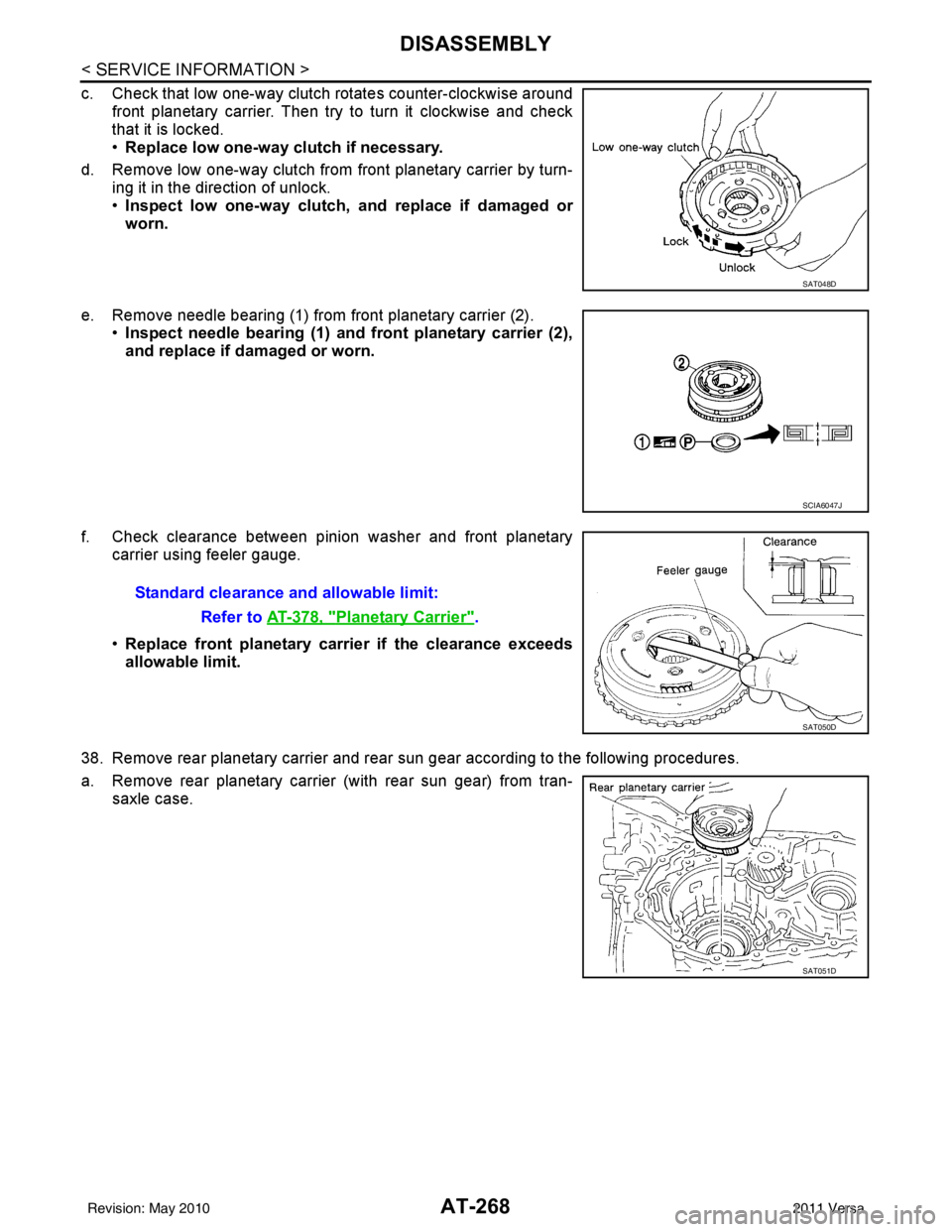
c. Check that low one-way clutch rotates counter-clockwise aroundfront planetary carrier. Then try to turn it clockwise and check
that it is locked.
•Replace low one-way clutch if necessary.
d. Remove low one-way clutch from front planetary carrier by turn- ing it in the direction of unlock.
•Inspect low one-way clutch, and replace if damaged or
worn.
e. Remove needle bearing (1) from front planetary carrier (2). •Inspect needle bearing (1) and front planetary carrier (2),
and replace if damaged or worn.
f. Check clearance between pinion washer and front planetary carrier using feeler gauge.
•Replace front planetary carrier if the clearance exceeds
allowable limit.
38. Remove rear planetary carrier and rear sun gear according to the following procedures.
a. Remove rear planetary carrier (with rear sun gear) from tran- saxle case.
SAT048D
SCIA6047J
Standard clearance and allowable limit:
Refer to AT-378, "
Planetary Carrier".
SAT050D
SAT051D
Revision: May 2010 2011 Versa
Page 332 of 3787

REPAIR FOR COMPONENT PARTSAT-315
< SERVICE INFORMATION >
DE
F
G H
I
J
K L
M A
B
AT
N
O P
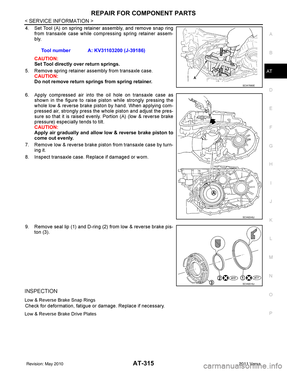
4. Set Tool (A) on spring retainer assembly, and remove snap ring from transaxle case while compressing spring retainer assem-
bly.
CAUTION:
Set Tool directly over return springs.
5. Remove spring retainer assembly from transaxle case. CAUTION:
Do not remove return springs from spring retainer.
6. Apply compressed air into the oil hole on transaxle case as shown in the figure to raise piston while strongly pressing the
whole low & reverse brake piston by hand. When applying com-
pressed air, strongly press the whole piston and adjust the pres-
sure so that it is raised evenly. Portion (A) (low & reverse brake
pressure) especially tends to tilt.
CAUTION:
Apply air gradually and allow low & reverse brake piston to
come out evenly.
7. Remove low & reverse brake piston from transaxle case by turn- ing it.
8. Inspect transaxle case. Replace if damaged or worn.
9. Remove seal lip (1) and D-ring (2) from low & reverse brake pis- ton (3).
INSPECTION
Low & Reverse Brake Snap Rings
Check for deformation, fatigue or damage. Replace if necessary.
Low & Reverse Brake Drive Plates
Tool number A: KV31103200 (J-39186)
SCIA7990E
SCIA6346J
SCIA6516J
Revision: May 2010 2011 Versa
Page 335 of 3787
AT-318
< SERVICE INFORMATION >
REPAIR FOR COMPONENT PARTS
• MR18DE engine models
(1): Snap ring
(2): Retaining plate
(3): Drive plate
(4): Driven plate
(5): Retaining plate
(6): Dish plate
Drive plate/Driven plate: 5/5
CAUTION:
Be careful with the order of plates
NOTE:
Install two dish plates fitting each installation direction with
groove displaced slightly.
6. Install snap ring (1) using a suitable tool (A).
7. Measure clearance between retaining plate and snap ring. If not within allowable limit, select proper retaining plate (front side).
Refer to “Parts Information” for retaining plate selection.
8. Check operation of low & revers e brake. Refer to "DISASSEM-
BLY".
Rear Internal Gear and Forward Clutch HubINFOID:0000000005928299
COMPONENTS
SAT254E
SCIA7039E
Specified clearance
Standard and allowable limit: Refer to AT-376, "
Clutches and Brakes".
SAT246D
Revision: May 2010 2011 Versa