2011 NISSAN TIIDA RON 91
[x] Cancel search: RON 91Page 46 of 3787
A/T CONTROL SYSTEMAT-29
< SERVICE INFORMATION >
DE
F
G H
I
J
K L
M A
B
AT
N
O P
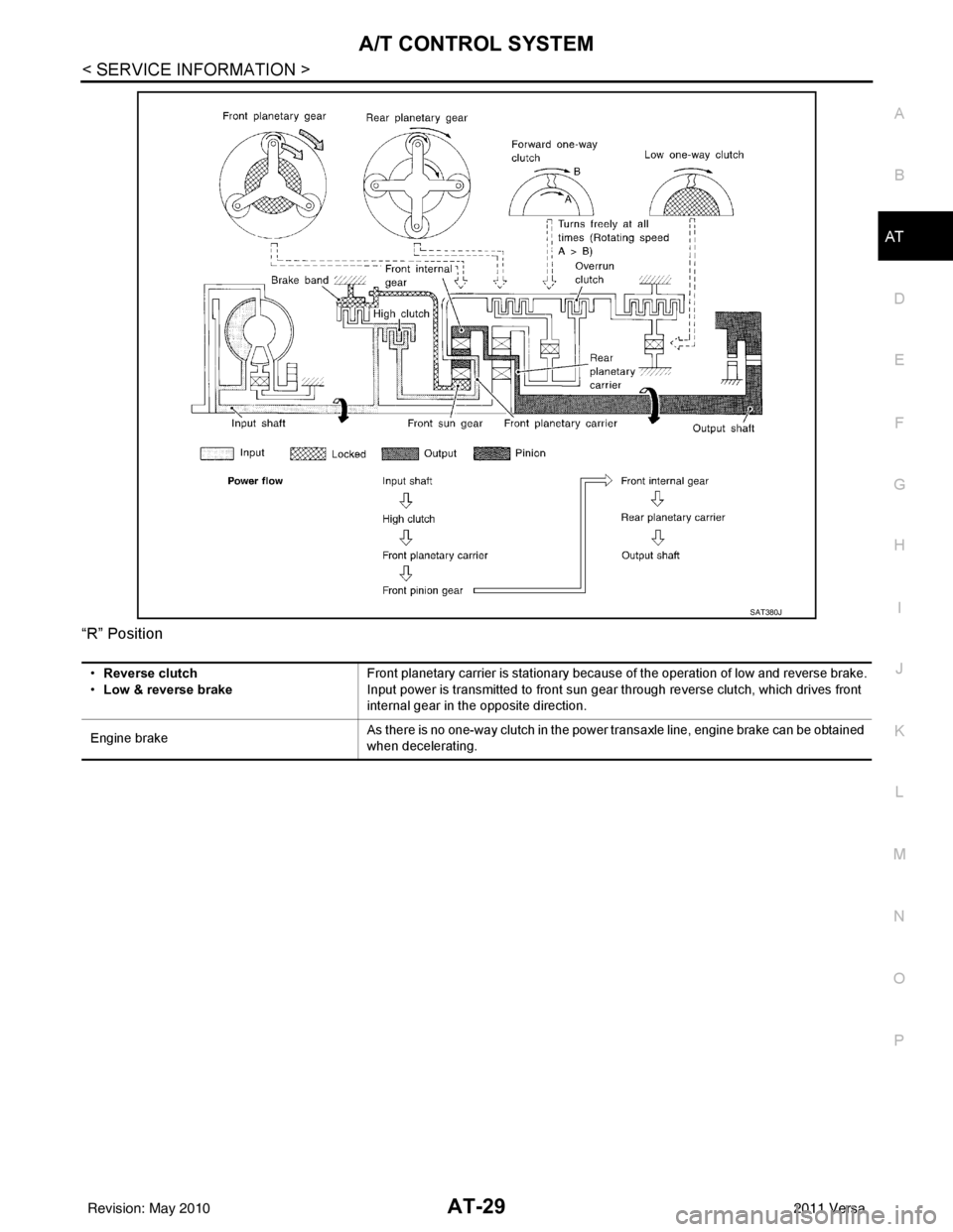
“R” Position
SAT380J
•
Reverse clutch
• Low & reverse brake Front planetary carrier is stationary because of the operation of low and reverse brake.
Input power is transmitted to front sun gear through reverse clutch, which drives front
internal gear in the opposite direction.
Engine brake As there is no one-way clutch in the power transaxle line, engine brake can be obtained
when decelerating.
Revision: May 2010
2011 Versa
Page 48 of 3787
A/T CONTROL SYSTEMAT-31
< SERVICE INFORMATION >
DE
F
G H
I
J
K L
M A
B
AT
N
O P
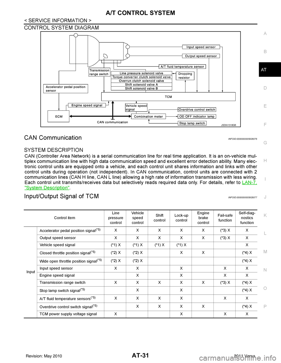
CONTROL SYSTEM DIAGRAM
CAN CommunicationINFOID:0000000005928076
SYSTEM DESCRIPTION
CAN (Controller Area Network) is a serial communication line for real time application. It is an on-vehicle mul-
tiplex communication line with high data communication speed and excellent error detection ability. Many elec-
tronic control units are equipped onto a vehicle, and each control unit shares information and links with other
control units during operation (not independent). In CAN communication, control units are connected with 2
communication lines (CAN H line, CAN L line) allowing a high rate of information transmission with less wiring.
Each control unit transmits/receives data but selectively reads required data only. For details, refer to LAN-7,
"System Description".
Input/Output Signal of TCMINFOID:0000000005928077
JSDIA1518GB
Control itemLine
pressure control Veh icl e
speed
control Shift
control Lock-up
control Engine
brake
control Fail-safe
function Self-diag-
nostics
function
Input Accelerator pedal position signal
(*5)XXXXX(*3) XX
Output speed sensor X X X X X (*3) X X
Vehicle speed signal (*1) X (*1) X (*1) X (*1) X X
Closed throttle position signal
(*5)(*2) X (*2) X X X(*4) X
Wide open throttle position signal
(*5)(*2) X (*2) X (*4) X
Input speed sensor X XXX X
Engine speed signal XXX X
Transmission range sw itch XXXXX(*3) X(*4) X
Stop lamp switch signal
(*5)XX ( *4 ) X
A/T fluid temperature sensors
(*5)XXXX XX
Overdrive control switch signal
(*5)XXXX (*4) X
TCM power supply voltage signal X XX X
Revision: May 2010 2011 Versa
Page 49 of 3787
AT-32
< SERVICE INFORMATION >
A/T CONTROL SYSTEM
*1: Output speed sensor
*2: Spare for accelerator pedal position signal
*3: If these input and output signals are different, the TCM triggers the fail-safe function.
*4: Used as a condition for starting self-diagnostics; if self-diagnosis are not started, it is judged that there is some kind of error.
*5: Input by CAN communications.
*6: Output by CAN communications.
Line Pressure ControlINFOID:0000000005928078
• TCM has various line pressure control char acteristics to match the driving conditions.
• An ON-OFF duty signal is sent to the line pres sure solenoid valve based on TCM characteristics.
• Hydraulic pressure on the clutch and brake is electronically controlled through the line pressure solenoid valve to accommodate engine torque. This results in smooth shift operation.
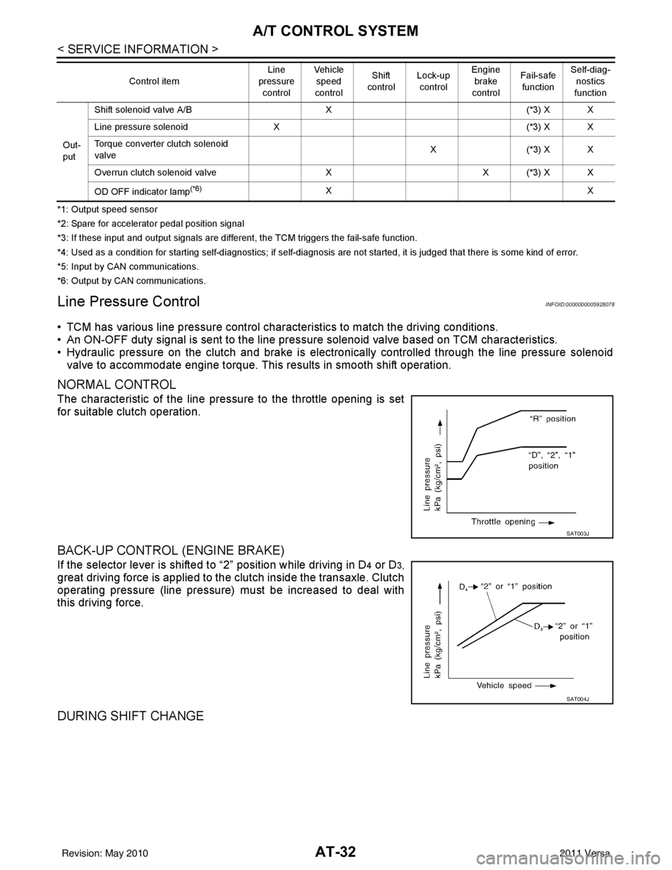
NORMAL CONTROL
The characteristic of the line pressure to the throttle opening is set
for suitable clutch operation.
BACK-UP CONTROL (ENGINE BRAKE)
If the selector lever is shifted to “2” position while driving in D4 or D3,
great driving force is applied to the clutch inside the transaxle. Clutch
operating pressure (line pressure) must be increased to deal with
this driving force.
DURING SHIFT CHANGE
Out-
put Shift solenoid valve A/B
X(*3) X X
Line pressure solenoid X (*3) X X
Torque converter clutch solenoid
valve X(
*3 ) X X
Overrun clutch solenoid valve XX (*3) X X
OD OFF indicator lamp
(*6)XX
Control item
Line
pressure
control Vehicle
speed
control Shift
control Lock-up
control Engine
brake
control Fail-safe
function Self-diag-
nostics
function
SAT003J
SAT004J
Revision: May 2010 2011 Versa
Page 50 of 3787
A/T CONTROL SYSTEMAT-33
< SERVICE INFORMATION >
DE
F
G H
I
J
K L
M A
B
AT
N
O P
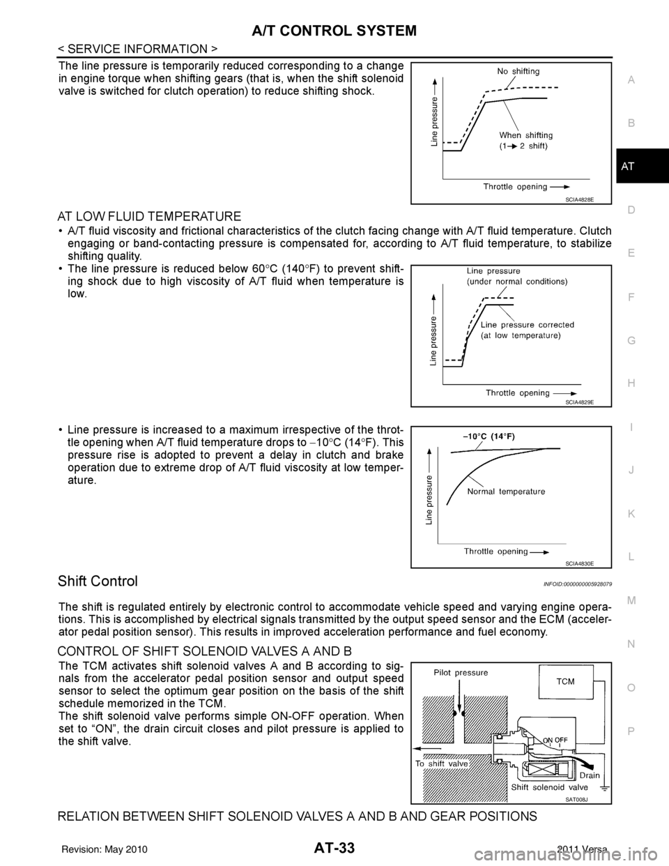
The line pressure is temporarily reduced corresponding to a change
in engine torque when shifting gears (that is, when the shift solenoid
valve is switched for clutch operation) to reduce shifting shock.
AT LOW FLUID TEMPERATURE
• A/T fluid viscosity and frictional characteristics of t he clutch facing change with A/T fluid temperature. Clutch
engaging or band-contacting pressure is compensated for, according to A/T fluid temperature, to stabilize
shifting quality.
• The line pressure is reduced below 60 °C (140° F) to prevent shift-
ing shock due to high viscosity of A/T fluid when temperature is
low.
• Line pressure is increased to a maximum irrespective of the throt- tle opening when A/T fluid temperature drops to −10° C (14° F). This
pressure rise is adopted to prevent a delay in clutch and brake
operation due to extreme drop of A/T fluid viscosity at low temper-
ature.
Shift ControlINFOID:0000000005928079
The shift is regulated entirely by electronic cont rol to accommodate vehicle speed and varying engine opera-
tions. This is accomplished by electrical signals trans mitted by the output speed sensor and the ECM (acceler-
ator pedal position sensor). This results in improved acceleration performance and fuel economy.
CONTROL OF SHIFT SOLENOID VALVES A AND B
The TCM activates shift solenoid valves A and B according to sig-
nals from the accelerator pedal position sensor and output speed
sensor to select the optimum gear position on the basis of the shift
schedule memorized in the TCM.
The shift solenoid valve performs simple ON-OFF operation. When
set to “ON”, the drain circuit closes and pilot pressure is applied to
the shift valve.
RELATION BETWEEN SHIFT SOLENOID VALVES A AND B AND GEAR POSITIONS
SCIA4828E
SCIA4829E
SCIA4830E
SAT008J
Revision: May 2010 2011 Versa
Page 59 of 3787
AT-42
< SERVICE INFORMATION >
TROUBLE DIAGNOSIS
TROUBLE DIAGNOSIS
DTC Inspection Priority ChartINFOID:0000000005928089
If some DTCs are displayed at the same time, perform inspections one by one based on the following priority
chart.
NOTE:
If DTC “CAN COMM CIRCUIT” is displayed with other DTCs, first perform the trouble diagnosis for
DTC “CAN COMM CIRCUIT”. Refer to AT- 8 7
.
Fail-SafeINFOID:0000000005928090
The TCM has an electronic Fail-safe mode. This allows t he vehicle to be driven even if a major electrical input/
output device circuit is damaged.
Under Fail-Safe, the vehicle always runs in 3GR, even wit h a shift lever position of “1”, “2” or “D”. The cus-
tomer may complain of sluggish or poor acceleration.
Always follow the “ AT-43, "
How to Perform Trouble Diagnosis for Quick and Accurate Repair" ”.
The SELF-DIAGNOSIS results will be as follows:
• The first SELF-DIAGNOSIS will indicate damage to the vehicle speed signal or the output speed sensor.
• During the next SELF-DIAGNOSIS, performed after checking the sensor, no damages will be indicated.
FAIL-SAFE FUNCTION
The following fail-safe functions allow vehicles to be driven even when sensor, switch or solenoid malfunction
occurs.
Output Speed Sensor
Vehicle speed signal is input from combination meter.
Accelerator Pedal Position Signal and Throttle Position Signal
TCM controls the throttle opening angle to a predetermined fixed position to enable driving if a malfunctioning
signal is input to TCM.
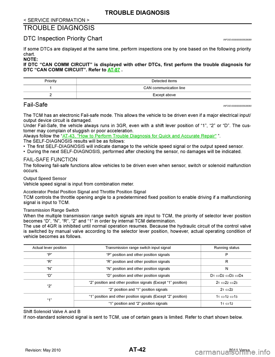
Transmission Range Switch
When the multiple transmission range switch signals are input to TCM, the priority of selector lever position
becomes “D”, “N”, “R”, “2” and “1” in order by internal TCM determination.
The use of 4GR is inhibited until normal operation resumes. Because the hydraulic circuit of the control valve
is switched by manual valve according to the selector lever position, however, actual operating condition of
vehicle becomes as follows.
Shift Solenoid Valve A and B
If non-standard solenoid signal is sent to TCM, use of certain gears is limited. Refer to chart shown below.
Priority Detected items
1 CAN communication line
2 Except above
Actual lever positionTransmission range switch input signal Running status
“P” “P” position and other position signals P
“R” “R” position and other position signals R
“N” “N” position and other position signals N
“D” “D” position and other position signals D
1 ⇔ D2 ⇔ D3 ⇔ D4
“2” “2” position and other position signals (Except “1” position)
21 ⇔ 22 ⇔ 23
“2” position and “1” position signals 21 ⇔ 22
“1” “1” position and other position signals (Except “2” position)
11 ⇔ 12 ⇔ 13
“1” position and “2” position signals 11 ⇔ 12
Revision: May 2010 2011 Versa
Page 61 of 3787
AT-44
< SERVICE INFORMATION >
TROUBLE DIAGNOSIS
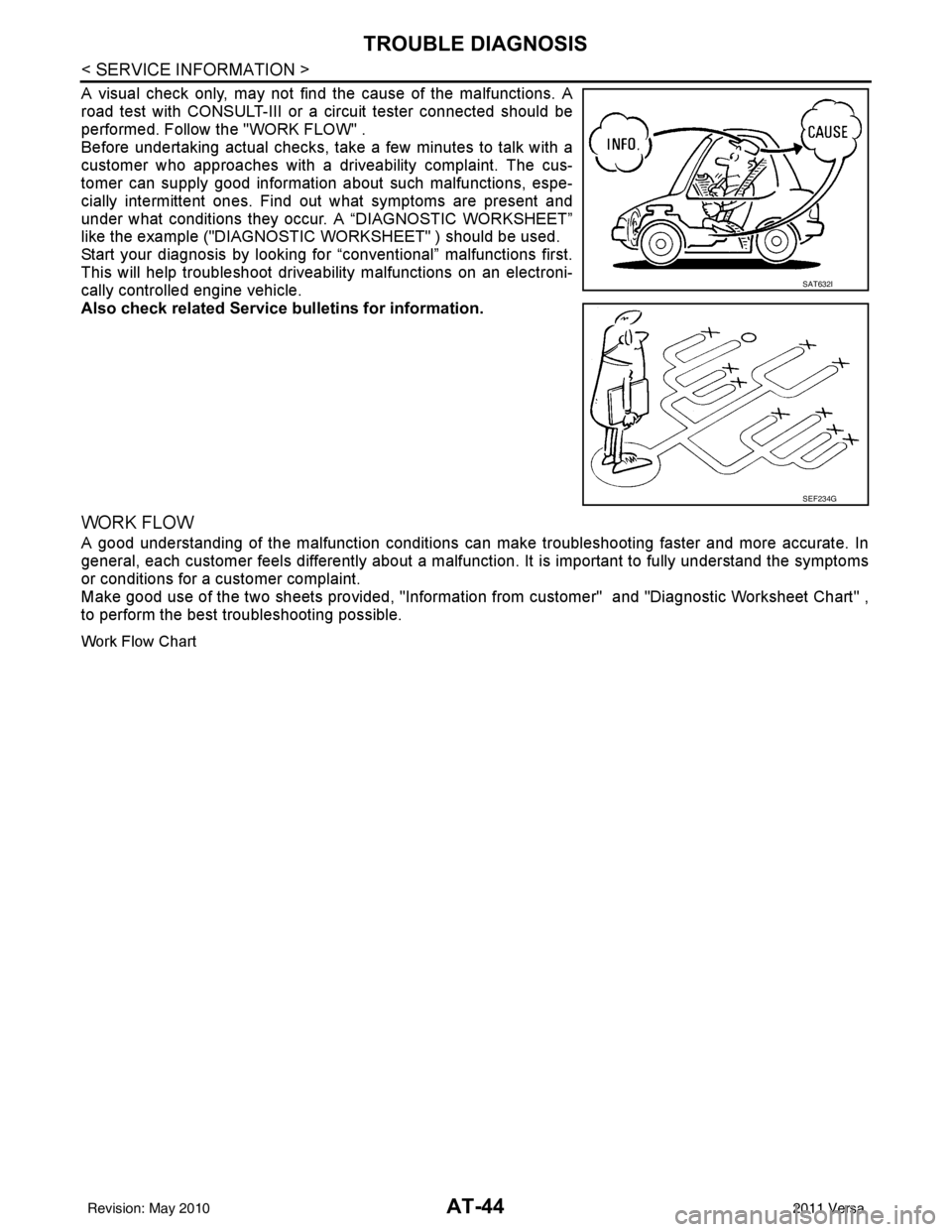
A visual check only, may not find the cause of the malfunctions. A
road test with CONSULT-III or a circuit tester connected should be
performed. Follow the "WORK FLOW" .
Before undertaking actual checks, take a few minutes to talk with a
customer who approaches with a driveability complaint. The cus-
tomer can supply good information about such malfunctions, espe-
cially intermittent ones. Find out what symptoms are present and
under what conditions they occu r. A “DIAGNOSTIC WORKSHEET”
like the example ("DIAGNOSTIC WORKSHEET" ) should be used.
Start your diagnosis by looking for “conventional” malfunctions first.
This will help troubleshoot driveability malfunctions on an electroni-
cally controlled engine vehicle.
Also check related Service bulletins for information.
WORK FLOW
A good understanding of the malfunction conditions can make troubleshooting faster and more accurate. In
general, each customer feels differently about a malfuncti on. It is important to fully understand the symptoms
or conditions for a customer complaint.
Make good use of the two sheets provided, "Information from customer" and "Diagnostic Worksheet Chart" ,
to perform the best troubleshooting possible.
Work Flow Chart
SAT632I
SEF234G
Revision: May 2010 2011 Versa
Page 104 of 3787
U1000 CAN COMM CIRCUITAT-87
< SERVICE INFORMATION >
DE
F
G H
I
J
K L
M A
B
AT
N
O P
U1000 CAN COMM CIRCUIT
DescriptionINFOID:0000000005928107
CAN (Controller Area Network) is a serial communication line for real time application. It is an on-vehicle mul-
tiplex communication line with high data communica tion speed and excellent malfunction detection ability.
Many electronic control units are equipped onto a vehicle, and each control unit shares information and links
with other control units during operation (not independent). In CAN communication, control units are con-
nected with 2 communication lines (CAN H line, CAN L li ne) allowing a high rate of information transmission
with less wiring. Each control unit transmits/recei ves data but selectively reads required data only.
On Board Diagnosis LogicINFOID:0000000005928108
• This is an OBD-II self-diagnostic item.
• Diagnostic trouble code “U1000 CAN COMM CIRCUIT” wit h CONSULT-III or 12th judgement flicker without
CONSULT-III is detected when TCM cannot communicate to other control units.
Possible CauseINFOID:0000000005928109
Harness or connector
(CAN communication line is open or shorted.)
DTC Confirmation ProcedureINFOID:0000000005928110
CAUTION:
If performing this “DTC Confirmation Procedure” again, always turn ignition switch OFF and wait at
least 10 seconds before continuing.
After the repair, perform the following procedure to confirm the malfunction is eliminated.
WITH CONSULT-III
1. Turn ignition switch ON.
2. Select “DATA MONITOR” mode for “TRANSMISSION” with CONSULT-III.
3. Touch “START”.
4. Wait at least 6 seconds or start engine and wait for at least 6 seconds.
5. If DTC is detected, go to AT-89, "
Diagnosis Procedure".
WITH GST
Follow the procedure “WITH CONSULT-III”.
WITHOUT CONSULT-III
1. Turn ignition switch ON.
2. Wait at least 6 seconds or start engine and wait at least 6 seconds.
3. Perform self-diagnosis. Refer to AT-82, "
Diagnosis Procedure without CONSULT-III".
4. If DTC is detected, go to AT-89, "
Diagnosis Procedure".
Revision: May 2010 2011 Versa
Page 231 of 3787
AT-214
< SERVICE INFORMATION >
SHIFT CONTROL SYSTEM
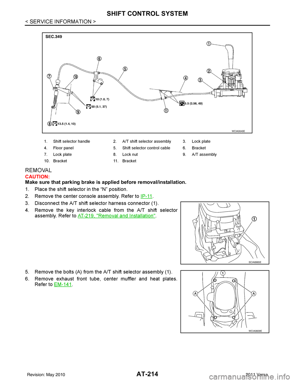
REMOVAL
CAUTION:
Make sure that parking brake is applied before removal/installation.
1. Place the shift selector in the “N” position.
2. Remove the center console assembly. Refer to IP-11
.
3. Disconnect the A/T shift selector harness connector (1).
4. Remove the key interlock cable from the A/T shift selector assembly. Refer to AT-219, "
Removal and Installation".
5. Remove the bolts (A) from the A/T shift selector assembly (1).
6. Remove exhaust front tube, center muffler and heat plates. Refer to EM-141
.
1. Shift selector handle 2. A/T shift selector assembly 3. Lock plate
4. Floor panel 5. Shift selector control cable 6. Bracket
7. Lock plate 8. Lock nut 9. A/T assembly
10. Bracket 11. Bracket
WCIA0640E
SCIA6965E
WCIA0609E
Revision: May 2010 2011 Versa