2011 NISSAN TIIDA cvt
[x] Cancel search: cvtPage 3479 of 3787

HARNESSPG-59
< SERVICE INFORMATION >
C
DE
F
G H
I
J
L
M A
B
PG
N
O P
H/LAMP LT Headlamp
H/PHON AV Hands Free Telephone
HORN WW Horn
HO2S2 EC Heated Oxygen Sensor 2
HO2S2H EC Heated Oxygen Sensor 2 Heater
IATS EC Intake Air Temperature Sensor
IGNSYS EC Ignition System
I/KEY BL Intelligent Key System
ILL LT Illumination
INJECT EC Injector
INT/L LT Room/Map, Vanity and Luggage Lamps
IVC EC Intake Valve Timing Control Solenoid Valve
KEYLES BL Remote Keyless Entry System
KS EC Knock Sensor
LPSV AT Line Pressure Solenoid Valve
LPSV CVT Line Pressure Solenoid Valve
L/USSV CVT Lock-up Select Solenoid Valve
MAFS EC Mass Air Flow Sensor
MAIN AT Main Power Supply and Ground Circuit
MAIN EC Main Power Supply and Ground Circuit
METER DI Speedometer, Tachometer, Temp. and Fuel Gauges
MIL/DL EC Malfunction Indicator Lamp
MIRROR GW Door Mirror
NATS BL Nissan Anti-Theft System
NONDTC AT Non-detectable Item
NONDTC CVT Non-detectable Item
ODSW CVT Overdrive Control Switch
OVRCSV AT Over Run Clutch Solenoid Valve
P/SCKT WW Power Socket
PGC/V EC EVAP Canister Purge Vo lume Control Solenoid Valve
PHASE EC Camshaft Position Sensor (PHASE)
PNP/SW EC Park/Neutral Position Switch
POS EC Crankshaft Position Sensor (POS)
POWER CVT Transmission Control Module (Power Supply)
PRE/SE EC EVAP Control System Pressure Sensor
PRIPS CVT Primary Pressure Sensor
PRSCVT CVT Primary Speed Sensor CVT (Input Speed Sensor)
PT/SEN AT Powertrain Revolution Sensor
RP/SEN EC Refrigerant Pressure Sensor
SECPS CVT Secondary Pressure Sensor
SECPSV CVT Secondary Speed Sensor CVT (Input Speed Sensor)
SEN/PW EC Sensor Power Supply
SESCVT CVT Secondary Pressure Sensor Solenoid Valve
SHIFT AT A/T Shift Lock System
SHIFT CVT CVT Shift Lock System
SROOF RF Sunroof
SRS SRS Supplemental Restraint System
SSV/A AT Shift Solenoid Valve A
SSV/B AT Shift Solenoid Valve B
START SC Starting System
STM CVT Step Motor
STOP/L LT Stop Lamp
Revision: May 2010 2011 Versa
Page 3480 of 3787

PG-60
< SERVICE INFORMATION >
HARNESS
TCVAT Torque Converter Clutch Solenoid Valve
TCV CVT Torque Converter Clutch Solenoid Valve
T/LID BL Trunk Lid Opener
T/WARN WT Low Tire Pressure Warning System
TAIL/L LT Parking, License and Tail Lamps
TPS1 EC Throttle Position Sensor
TPS2 EC Throttle Position Sensor
TPS3 EC Throttle Position Sensor
TR/SW AT Transmission Range Switch
TR/SW CVT Transmission Range Switch
TURN LT Turn Signal and Hazard Warning Lamps
VDC BRC Vehicle Dynamic Control System
VEHSEC BL Vehicle Security (Theft Warning) System
VENT/V EC EVAP Canister Vent Control Valve
VSSA/T AT Vehicle Speed Sensor A/T (Input Speed Sensor)
VSSMTR AT Vehicle Speed Sensor MTR
WARN DI Warning Lamps
WINDOW GW Power Window
WIP/R WW Rear Wiper and Washer
WIPER WW Front Wiper and Washer
Revision: May 2010 2011 Versa
Page 3529 of 3787

RF-6
< SYMPTOM DIAGNOSIS >
SQUEAK AND RATTLE TROUBLE DIAGNOSES
If possible, drive the vehicle with the customer until the noise is duplicated. Note any additional information on
the Diagnostic Worksheet regarding the conditions or lo cation of the noise. This information can be used to
duplicate the same conditions when you confirm the repair.
If the noise can be duplicated easily during the test drive, to help identify the source of the noise, try to dupli-
cate the noise with the vehicle stopped by doing one or all of the following:
1) Close a door.
2) Tap or push/pull around the area where the noise appears to be coming from.
3) Rev the engine.
4) Use a floor jack to recreate vehicle “twist”.
5) At idle, apply engine load (electrical load, half-clutch on M/T model, drive position on CVT and A/T models).
6) Raise the vehicle on a hoist and hit a tire with a rubber hammer.
• Drive the vehicle and attempt to duplicate the conditions the customer states exist when the noise occurs.
• If it is difficult to duplicate the noise, drive the v ehicle slowly on an undulating or rough road to stress the
vehicle body.
CHECK RELATED SERVICE BULLETINS
After verifying the customer concern or symptom, chec k ASIST for Technical Service Bulletins (TSBs) related
to that concern or symptom.
If a TSB relates to the symptom, follo w the procedure to repair the noise.
LOCATE THE NOISE AND IDENTIFY THE ROOT CAUSE
1. Narrow down the noise to a general area. To help pi npoint the source of the noise, use a listening tool
(Engine Ear or mechanics stethoscope).
2. Narrow down the noise to a more specific area and identify the cause of the noise by:
• removing the components in the area that you suspect the noise is coming from.
Do not use too much force when removing clips and fasteners, otherwise clips and fastener can be broken
or lost during the repair, resulting in the creation of new noise.
• tapping or pushing/pulling the component that you suspect is causing the noise.
Do not tap or push/pull the component with excessive force, otherwise the noise will be eliminated only tem-
porarily.
• feeling for a vibration with your hand by touching the component(s) that you suspect is (are) causing the
noise.
• placing a piece of paper between components that you suspect are causing the noise.
• looking for loose components and contact marks. Refer to RF-7, "
Generic Squeak and Rattle Troubleshooting".
REPAIR THE CAUSE
• If the cause is a loose component, tighten the component securely.
• If the cause is insufficient clearance between components:
- separate components by repositioning or loos ening and retightening the component, if possible.
- insulate components with a suitable insulator such as urethane pads, foam blocks, felt cloth tape or urethane tape are available through your authorized Nissan Parts Department.
CAUTION:
Do not use excessive force as many components are constructed of plastic and may be damaged.
NOTE:
Always check with the Parts Departm ent for the latest parts information.
Each item can be ordered separately as needed.
URETHANE PADS [1.5 mm (0.059 in) thick]
Insulates connectors, harness, etc.
76268-9E005: 100 × 135 mm (3.94 × 5.31 in)/76884-71L01: 60 × 85 mm (2.36 × 3.35 in)/76884-71L02: 15 ×
25 mm (0.59 × 0.98 in)
INSULATOR (Foam blocks)
Insulates components from contact. Can be used to fill space behind a panel.
73982-9E000: 45 mm (1.77 in) thick, 50 × 50 mm (1.97 × 1.97 in)/73982-50Y00: 10 mm (0.39 in) thick, 50
× 50 mm (1.97 × 1.97 in)
INSULATOR (Light foam block)
80845-71L00: 30 mm (1.18 in) thick, 30 × 50 mm (1.18 × 1.97 in)
FELT CLOTH TAPE
Used to insulate where movement does not occu r. Ideal for instrument panel applications.
68370-4B000: 15 × 25 mm (0.59 × 0.98 in) pad/68239-13E00: 5 mm (0.20 in) wide tape roll
Revision: May 2010 2011 Versa
Page 3585 of 3787

BATTERYSC-7
< SERVICE INFORMATION >
C
DE
F
G H
I
J
L
M A
B
SC
N
O P
CHARGING THE BATTERY
CAUTION:
• Do not “quick charge” a fully discharged battery.
• Keep the battery away from open flame while it is being charged.
• When connecting the charger, connect the leads first, then turn on the charger. Do not turn on the
charger first, as this may cause a spark.
• If battery electrolyte temperature rises above 55 °C (131 °F), stop charging. Alw ays charge battery at a
temperature below 55 °C (131° F).
Charging Rates
Do not charge at more than 50 ampere rate.
NOTE:
The ammeter reading on your battery charger will automatically decrease as the battery charges. This indi-
cates that the voltage of the battery is increasing norma lly as the state of charge improves. The charging amps
indicated above refer to initial charge rate.
• If, after charging, the specific gravity of any two cells varies more than 0.050, the battery should be replaced.
Trouble Diagnosis with Multita sking Battery Diagnostic StationINFOID:0000000005929011
Refer to diagnostic station instruction manual.
Removal and InstallationINFOID:0000000005929012
REMOVAL (All except MR18DE with CVT)
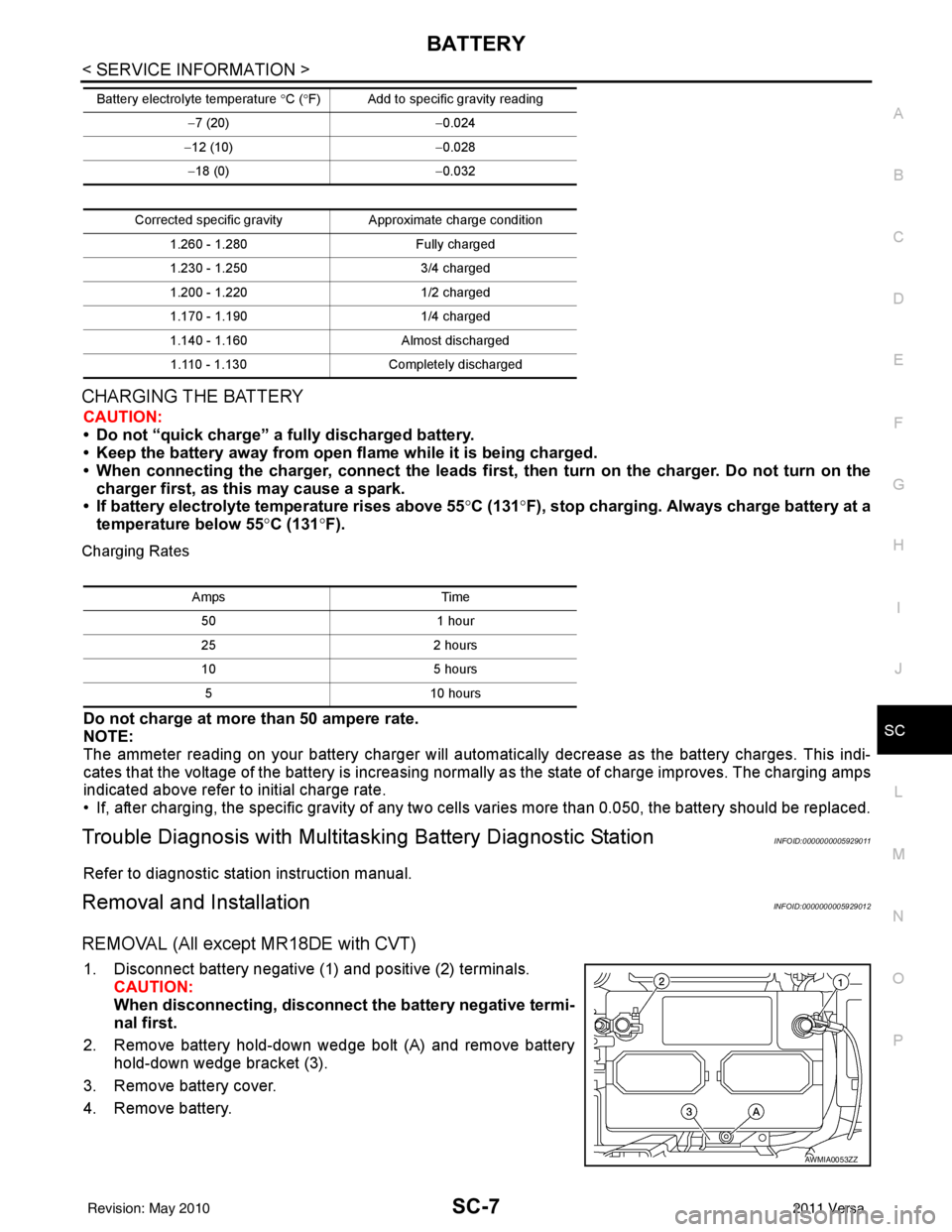
1. Disconnect battery negative (1) and positive (2) terminals.
CAUTION:
When disconnecting, disconnect the battery negative termi-
nal first.
2. Remove battery hold-down wedge bolt (A) and remove battery hold-down wedge bracket (3).
3. Remove battery cover.
4. Remove battery.
− 7 (20) −0.024
− 12 (10) −0.028
− 18 (0) −0.032
Corrected specific gravity Approximate charge condition
1.260 - 1.280 Fully charged
1.230 - 1.250 3/4 charged
1.200 - 1.220 1/2 charged
1.170 - 1.190 1/4 charged
1.140 - 1.160 Almost discharged
1.110 - 1.130 Completely discharged
Battery electrolyte temperature °
C (°F) Add to specific gravity reading
Amps Time
50 1 hour
25 2 hours
10 5 hours
5 10 hours
AWMIA0053ZZ
Revision: May 2010 2011 Versa
Page 3586 of 3787

SC-8
< SERVICE INFORMATION >
BATTERY
INSTALLATION (All except MR18DE with CVT)
Installation is in the reverse order of removal.
CAUTION:
When connecting, connect the battery positive terminal first.
Reset electronic systems as necessary. Refer to SC-8, "
Required Procedure After Battery Disconnection".
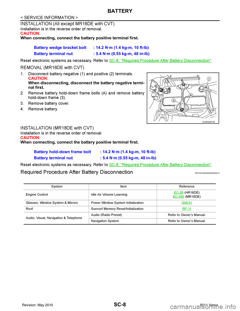
REMOVAL (MR18DE with CVT)
1. Disconnect battery negative (1) and positive (2) terminals.
CAUTION:
When disconnecting, disconnect the battery negative termi-
nal first.
2. Remove battery hold-down frame bolts (A) and remove battery hold-down frame (3).
3. Remove battery cover.
4. Remove battery.
INSTALLATION (MR18DE with CVT)
Installation is in the reverse order of removal.
CAUTION:
When connecting, connect the battery positive terminal first.
Reset electronic systems as necessary. Refer to SC-8, "
Required Procedure After Battery Disconnection".
Required Procedure After Battery DisconnectionINFOID:0000000005929013
Battery wedge bracket bolt : 14.2 N·m (1.4 kg-m, 10 ft-lb)
Battery terminal nut : 5.4 N·m (0.55 kg-m, 48 in-lb)
ALMIA0487ZZ
Battery hold-down frame bolt : 14.2 N·m (1.4 kg-m, 10 ft-lb)
Battery terminal nut : 5.4 N·m (0.55 kg-m, 48 in-lb)
System ItemReference
Engine Control Idle Air Volume Learning EC-26
(HR16DE)
EC-580
(MR18DE)
Glasses, Window System & Mirrors Power Window System Initialization GW-31
RoofSunroof Memory Reset/Initialization RF-11
Audio, Visual, Navigation & TelephoneAudio (Radio Preset)
Refer to Owner’s Manual.
Navigation System Refer to Owner’s Manual.
Revision: May 2010 2011 Versa
Page 3587 of 3787

STARTING SYSTEMSC-9
< SERVICE INFORMATION >
C
DE
F
G H
I
J
L
M A
B
SC
N
O P
STARTING SYSTEM
System DescriptionINFOID:0000000005929014
M/T Models
Power is supplied at all times
• to starter motor terminal B, and
• through 40A fusible link (letter h, located in the fuse and fusible link box)
• to ignition switch terminal B.
With the ignition switch in the START position, power is supplied
• from ignition switch terminal ST
• to IPDM E/R terminal 21.
With the ignition switch in the ON or START position, power is supplied
• through 10A fuse (No. 49, located in the IPDM E/R)
• to the clutch interlock switch terminal 1.
With the clutch pedal depressed, power is supplied
• through the clutch interlock switch terminal 2
• to IPDM E/R terminal 35.
Ground is supplied at all times
• to IPDM E/R terminals 39 and 59
• through body grounds E15 and E24.
If the IPDM E/R receives a starter relay request ON signal from the BCM over the CAN communication lines,
the IPDM E/R grounds the starter relay and power is supplied
• through terminal 19 of the IPDM E/R
• to terminal S of the starter motor.
The starter motor magnetic switch energizes closing the circuit between the battery and the starter motor. The
starter motor is case ground through the cylinder block. With power and ground supplied, the starter motor
operates.
A/T Models
Power is supplied at all times
• to starter motor terminal B, and
• through 40A fusible link (letter h, located in the fuse and fusible link box)
• to ignition switch terminal B.
With the ignition switch in the START position, power is supplied
• from ignition switch terminal ST
• to IPDM E/R terminal 21.
With the ignition switch in the ON or START position, power is supplied
• through 10A fuse (No. 54, located in the IPDM E/R)
• to transmission range switch terminal 1.
With the selector lever in the P or N position, power is supplied
• through transmission range switch terminal 2
• to IPDM E/R terminal 35.
Ground is supplied at all times
• to IPDM E/R terminals 39 and 59
• through body grounds E15 and E24.
If the IPDM E/R receives a starter relay request ON signal from the BCM over the CAN communication lines,
the IPDM E/R grounds the starter relay and power is supplied
• through terminal 19 of the IPDM E/R
• to terminal S of the starter motor.
The starter motor magnetic switch energizes closing the circuit between the battery and the starter motor. The
starter motor is case ground through the cylinder block. With power and ground supplied, the starter motor
operates.
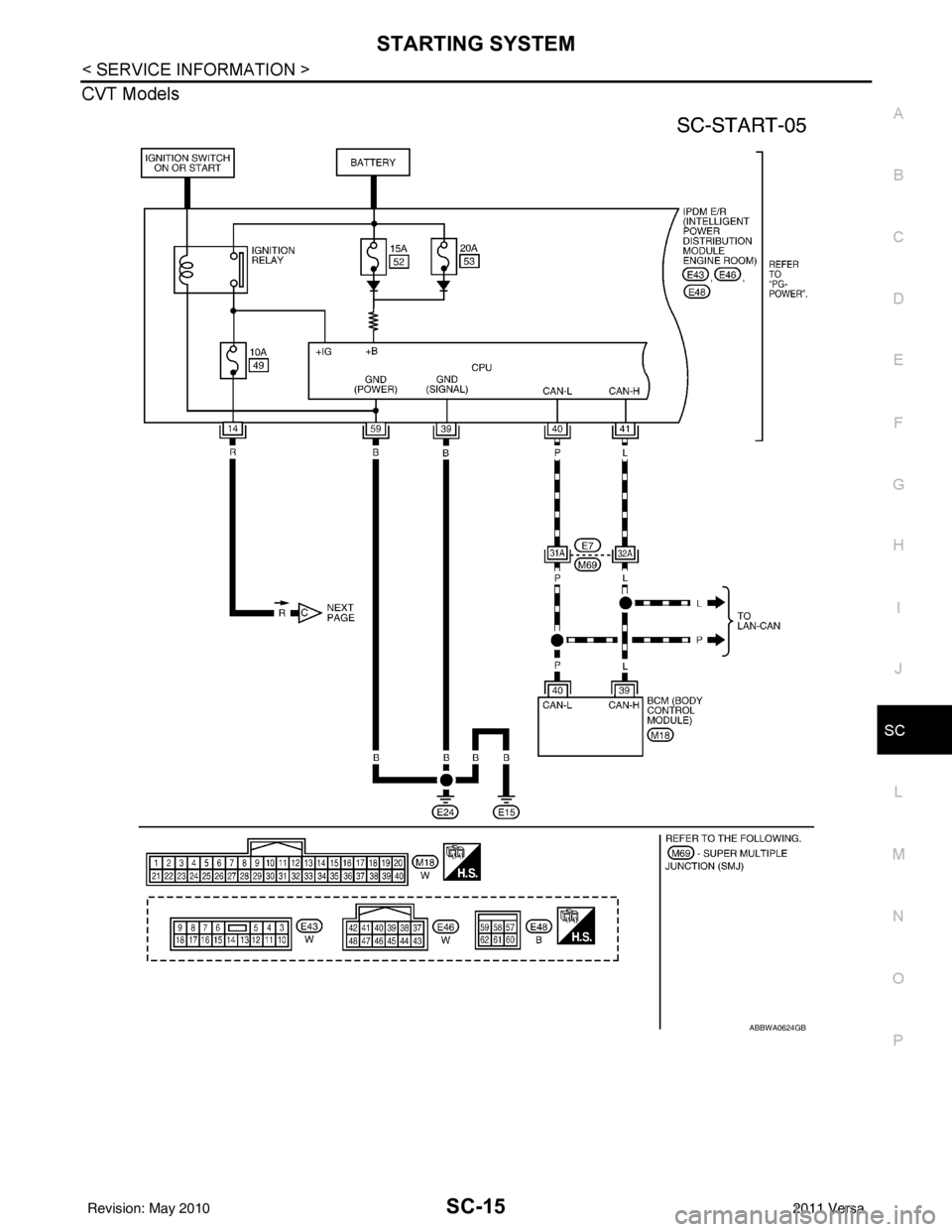
CVT Models
Power is supplied at all times
• to starter motor terminal B, and
• through 40A fusible link (letter h, located in the fuse and fusible link box)
• to ignition switch terminal B.
With the ignition switch in the ON or START position, power is supplied
• through 10A fuse (No. 49, located in the IPDM E/R)
Revision: May 2010 2011 Versa
Page 3593 of 3787

STARTING SYSTEMSC-15
< SERVICE INFORMATION >
C
DE
F
G H
I
J
L
M A
B
SC
N
O P
CVT Models
ABBWA0624GB
Revision: May 2010 2011 Versa
Page 3605 of 3787

SERVICE DATA AND SPECIFICATIONS (SDS)SC-27
< SERVICE INFORMATION >
C
DE
F
G H
I
J
L
M A
B
SC
N
O P
SERVICE DATA AND SPECIFICATIONS (SDS)
BatteryINFOID:0000000005929023
*: Always check with the Parts Department for the latest parts information
StarterINFOID:0000000005929024
*: Always check with the Parts Department for the latest parts information
GeneratorINFOID:0000000005929025
*: Always check with the Parts Department for the latest parts information Applied model MT, A/T CVT
Typ e*
T4Gr.51 R
20 hours rate capacity 12 V - 47 AH12 V - 43 AH
Cold Cranking Am ps. (CCA) 470410
Applied model HR16DEMR18DE
Typ e* S114-954
S114-955
HITACHI make HITACHI make
Reduction gear type Reduction gear type
System voltage 12 V12 V
No-load Terminal voltage
11 V11 V
Current Less than 110 ALess than 110 A
Revolution More than 3,000 rpmMore than 3,000 rpm
Applied model HR16DEMR18DE
Typ e* A002TJ0291ZC
A002TG1581AC
MITSUBISHI make MITSUBISHI make
Nominal rating 12 V - 100 A12 V - 100 A
Ground polarity NegativeNegative
Minimum revolution under no-load (when 13.5 V is
applied) Less than 1,000 rpm
Less than 1,000 rpm
Hot output current (when 13.5 V is applied) More than 27 A/1,300 rpm
More than 95 A/2,500 rpm
More than 116 A/5,000 rpm More than 16 A/1,300 rpm
More than 82 A/2,500 rpm
More than 97 A/5,000 rpm
Regulated output voltage 14.1 - 14.7 V14.1 - 14.7 V
Revision: May 2010 2011 Versa