2011 NISSAN TIIDA cvt
[x] Cancel search: cvtPage 1 of 3787

-1
QUICK REFERENCE INDEX
AGENERAL INFORMATIONGIGeneral Information
BENGINEEMEngine Mechanical
LUEngine Lubrication System
COEngine Cooling System
ECEngine Control System
FLFuel System
EXExhaust System
ACCAccelerator Control System
CTRANSMISSION/
TRANSAXLECLClutch System
MTManual Transaxle
ATAutomatic Transaxle
CVTCVT
DDRIVELINE/AXLEFAXFront Axle
RAXRear Axle
ESUSPENSIONFSUFront Suspension
RSURear Suspension
WTRoad Wheels & Tires
FBRAKESBRBrake System
PBParking Brake System
BRCBrake Control System
GSTEERINGPSPower Steering System
STCSteering Control System
HRESTRAINTSSBSeat Belts
SRSSupplemental Restraint System (SRS)
IBODYBLBody, Lock & Security System
GWGlasses, Window System & Mirrors
RFRoof
EIExterior & Interior
IPInstrument Panel
SESeat
JAIR CONDITIONERMTCManual Air Conditioner
KELECTRICALSCStarting & Charging System
LTLighting System
DIDriver Information System
WWWiper, Washer & Horn
BCSBody Control System
LANLAN System
AVAudio Visual, Navigation & Telephone System
ACSAuto Cruise Control System
PGPower Supply, Ground & Circuit Elements
LMAINTENANCEMAMaintenance
Edition: May 2010
Revision: May 2010
Publication No. SM1E-1C11U0
B
D
© 2010 NISSAN NORTH AMERICA, INC.
All rights reserved. No part of this Service Manual may be reproduced or stored in a retrieval system, or transmitted in any
form, or by any means, electronic, mechanical, photo-copying, recording or otherwise, without the prior written permission
of Nissan North America Inc.
A
C
E
F
G
H
I
J
K
L
M
Page 10 of 3787

2011
QUICK REFERENCE INDEX: VERSA
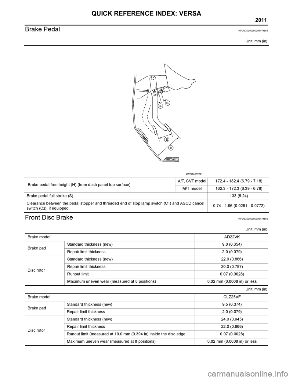
Brake Pedal
INFOID:0000000006444568
Unit: mm (in)
Front Disc BrakeINFOID:0000000006444565
Unit: mm (in)
Unit: mm (in)
Brake pedal free height (H) (from dash panel top surface) A/T, CVT model 172.4 - 182.4 (6.79 - 7.18)
M/T model 162.3 - 172.3 (6.39 - 6.78)
Brake pedal full stroke (S) 133 (5.24)
Clearance between the pedal stopper and threaded end of stop lamp switch (C
1) and ASCD cancel
switch (C
2), if equipped 0.74 - 1.96 (0.0291 - 0.0772)
AWFIA0557ZZ
Brake model
AD22VK
Brake pad Standard thickness (new) 9.0 (0.354)
Repair limit thickness 2.0 (0.079)
Disc rotor Standard thickness (new)
22.0 (0.866)
Repair limit thickness 20.0 (0.787)
Runout limit 0.07 (0.0028)
Maximum uneven wear (measured at 8 positions) 0.02 mm (0.0008 in) or less
Brake model CLZ25VF
Brake pad Standard thickness (new)
9.5 (0.374)
Repair limit thickness 2.0 (0.079)
Disc rotor Standard thickness (new)
24.0 (0.945)
Repair limit thickness 22.0 (0.866)
Runout limit (measured at 10.0 mm (0.394 in) inside the disc edge 0.07 (0.0028)
Maximum uneven wear (measured at 8 positions) 0.02 mm (0.0008 in) or less
Page 11 of 3787

QUICK REFERENCE INDEX: VERSA
2011
Rear Drum BrakeINFOID:0000000006444566
Unit: mm (in)
Unit: mm (in)
Fluids and LubricantsINFOID:0000000006444564
Brake modelLT 2 0
Brake lining Standard thickness (new)
4.0 (0.157)
Repair limit thickness 1.5 (0.059)
Drum Standard inner diameter (new)
203 (7.992)
Repair limit inner diameter 204.5 (8.051)
Brake model LT 2 3
Brake lining Standard thickness
(new) 4.0 (0.157)
Repair limit thickness 1.5 (0.059)
Drum Standard inner diameter (new)
228.6 (9.000)
Repair limit inner diameter 230.0 (9.055)
DescriptionCapacity (Approximate)
Liter US measure Imp measure
Fuel 50.013 1/4 gal 11 gal
Engine oil
Drain and refill With oil filter
change
HR16DE
3.03 1/8 qt 2 5/8 qt
MR18DE 4.14 3/8 qt 3 5/8 qt
Without oil filter
change HR16DE
2.83 qt2 1/2 qt
MR18DE 3.94 1/8 qt 3 3/8 qt
Dry engine (engine overhaul) HR16DE
3.53 3/4 qt 3 1/8 qt
MR18DE 4.95 1/8 qt 4 3/8 qt
Cooling system
(with reservoir at max level) HR16DE
6.36 5/8 qt 5 1/2 qt
MR18DE 6.87 1/4 qt 6 qt
Manual transaxle fluid (MTF) 5MT
2.65 1/2 pt 4 5/8 pt
6MT 2.04 1/4 pt 3 1/2 pt
Automatic transaxle fluid (ATF) HR16DE
7.78 1/8 qt 6 3/4 qt
MR18DE 7.98 3/8 qt 7 qt
CVT fluid RE0F08B6.97 1/4 qt 6 1/8 qt
Brake and clutch fluid —— —
Multi-purpose grease —— —
Windshield washer fluid 4.54 3/4 qt 4 qt
Air conditioning system refrigerant 0.45 ± 0.05 kg 0.99 ± 0.11 lb 0.99 ± 0.11 lb
Air conditioning system oil MR18DE - Type
1
and HR16DE
120 m
4.1 fl oz
4.2 fl oz
MR18DE - Type
2 100 m
3.4 fl oz
3.5 fl oz
Page 512 of 3787

BL-2
Keyfob Function (Lock) Check ...............................82
Keyfob Function (Unlock) Check ............................82
ID Code Entry Procedure .................................... ...83
Keyfob Battery Replacement ............................... ...85
Removal and Installation of Remote Keyless Entry
Receiver .............................................................. ...
85
INTELLIGENT KEY SYSTEM ............................86
Component Parts and Harness Connector Loca-
tion ....................................................................... ...
86
System Description .................................................88
CAN Communication System Description ..............95
Schematic ............................................................ ...96
Wiring Diagram - I/KEY - ..................................... ...98
Intelligent Key Unit Har ness Connector Terminal
Layout .................................................................. ..
108
Terminal and Reference Value for Intelligent Key
Unit ........................................................................
108
Steering Lock Solenoid Harness Connector Ter-
minal Layout ..........................................................
110
Terminal and Reference Value for Steering Lock
Solenoid .................................................................
110
Terminal and Reference Value for BCM ................111
Trouble Diagnosis Procedure ................................115
CONSULT-III Functions (INTELLIGENT KEY) ......117
CONSULT-III Application Item ............................. ..117
Trouble Diagnosis Symptom Chart ........................119
CAN Communication System Inspection ...............126
Power Supply and Ground Circuit Inspection ........126
Key Switch (Intelligent Key Unit Input) Check .......127
Key Switch (BCM Input) Check .............................128
Ignition Knob Switch Check ................................. ..129
Door Switch Check (Hatchback) ............................131
Door Switch Check (Sedan) ..................................134
Door Request Switch Check ..................................135
Back Door Request Switch Check (Hatchback) ....137
Trunk Opener Request Switch Check (Sedan) ... ..138
Unlock Sensor Check ............................................140
Intelligent Key Warning Buzzer(s) Check ..............142
Outside Key Antenna (Dri ver Side and Passenger
Side) Check ......................................................... ..
143
Outside Key Antenna (Rear Bumper) Check .........144
Inside Key Antenna Check ....................................146
Steering Lock Solenoid Check ............................ ..147
Key Interlock Solenoid (With M/T) Check ..............149
Ignition Switch Position Check ............................ ..150
Stop Lamp Switch Check (With CVT or A/T) ....... ..150
Stop Lamp Switch Check (With M/T) .....................152
CVT or A/T Shift Selector (Park Position Switch)
Check .................................................................. ..
153
"P-SHIFT" Warning Lamp (With CVT or A/T)
Check ....................................................................
154
"LOCK" Warning Lamp (With M/T) Check .............155
"KEY" Warning Lamp (RED) Check ......................155
"KEY" Warning Lamp (G REEN) Check .................155
Check Warning Chime in Combination Meter ........156
Hazard Function Check .........................................156
Horn Function Check .... .........................................157
Headlamp Function Chec k ....................................157
Intelligent Key Battery Re placement .....................158
Remote Keyless Entry Func tion ............................158
Removal and Installation of Intelligent Key Unit ... .158
DOOR ...............................................................160
Fitting Adjustment ................................................ .160
Removal and Installation .......................................163
Back Door Stay Disposal ..................................... .166
FRONT DOOR LOCK .......................................167
Component Parts Location .................................. .167
Removal and Installation .......................................167
REAR DOOR LOCK ....................................... ..170
Component Parts Location .................................. .170
Removal and Installation .......................................170
BACK DOOR LOCK ....................................... ..173
Component Parts and Harness Connector Loca-
tion ....................................................................... .
173
System Description ...............................................173
Wiring Diagram - B/DOOR - ..................................174
Terminal and Reference Value for BCM ...............176
Terminal and Reference Value for Intelligent Key
Unit ....................................................................... .
180
CONSULT-III Function (BCM) ..............................182
Work Flow .............................................................183
Trouble Diagnosis Chart by Symptom ..................183
BCM Power Supply and Ground Circuit Inspection
.
183
Check Back Door Opener Switch Circuit (Without
Intelligent Key or Power Windows) ...................... .
184
Check Back Door Opener Switch Circuit (Without
Intelligent Key, with Power Windows) .................. .
187
Check Back Door Opener Switch Circuit (With In-
telligent Key) ........................................................ .
189
Check Back Door Lock Assembly (Actuator) Cir-
cuit ........................................................................
191
Removal and Installation .......................................193
TRUNK LID ..................................................... ..195
Fitting Adjustment ................................................ .195
Trunk Lid Assembly ..............................................195
Trunk Lid Lock ......................................................196
Trunk Lid Striker ....................................................196
TRUNK LID OPENER .......................................198
Component Parts and Harness Connector Loca-
tion ....................................................................... .
198
System Description ...............................................198
Wiring Diagram - TLID - ........................................199
Terminal and Reference Value for BCM ...............201
Terminal and Reference Value for Intelligent Key
Unit ....................................................................... .
205
CONSULT-III Function (BCM) ..............................207
Work Flow .............................................................208
Trouble Diagnosis Chart by Symptom ..................208
BCM Power Supply and Ground Circuit Inspection
.
208
Revision: May 2010 2011 Versa
Page 533 of 3787

POWER DOOR LOCK SYSTEMBL-23
< SERVICE INFORMATION >
C
DE
F
G H
J
K L
M A
B
BL
N
O P
System DescriptionINFOID:0000000005929283
Power is supplied at all times
• through 40A fusible link (letter g, located in the fuse and fusible link box)
• to BCM terminal 70
• through 10A fuse [No. 8, located in the fuse block (J/B)]
• to BCM terminal 57
• through 10A fuse [No. 14, located in the fuse block (J/B)]
• to key switch terminal 2 (without Intelligent Key system)
• through 10A fuse [No. 31, located in the fuse block (J/B)]
• to key switch and ignition knob switch terminals 2 and 4 (with Intelligent Key system).
When key switch is ON (key is inserted in ignition key cylinder), power is supplied
• through key switch terminal 1 (without Intelligent Key system) or key switch and ignition knob terminal 1 (with Intelligent Key system)
• to BCM terminal 37.
Ground is supplied
• to BCM terminal 67
• through body grounds M57 and M61.
LOCK OPERATION
When the door is locked with main power window and door lock/unlock switch, ground is supplied
• to BCM terminal 45
• through main power window and door lock and unlock switch terminals 17 and 18
• through body grounds M57 and M61.
When the door is locked with power window and door lock/unlock switch RH, ground is supplied
• to BCM terminal 45
• through power window and door lock and unlock switch RH terminals 1 and 3
• through body grounds M57 and M61.
When the door is locked with front door lock assemb ly LH (key cylinder switch), ground is supplied
• to BCM terminal 8
• through front door lock assembly LH (key cylinder switch) terminals 4 and 6
• through body grounds M57 and M61.
UNLOCK OPERATION
When the door is unlocked with main power window and door lock/unlock switch, ground is supplied
• to BCM terminal 46
• through main power window and door lock/unlock switch terminals 6 and 17
• through body grounds M57 and M61.
When the door is unlocked with power window and door lock/unlock switch RH, ground is supplied
• to BCM terminal 46
• through power window and door lock and unlock switch RH terminals 2 and 3
• through body grounds M57 and M61.
When the door is unlocked with front door lock assemb ly LH (key cylinder switch), ground is supplied
• to BCM terminal 7
• through front door lock assembly LH (key cylinder switch) terminals 4 and 5
1. BCM M18, M19, M20
(view with glove box removed) 2. Intelligent Key unit M52
(if equipped) 3. Front door lock assembly LH (key cyl-
inder switch) D14
4. Front door switch LH B8, RH B108 5. Front door lock assembly LH (actuator) D14
Front door lock assembly RH (actuator)
D1146. Rear door switch LH B6, RH B116
7. Rear door lock actuator LH D205 RH D305 8. Key switch and ignition knob switch M73
(with A/T or CVT and Intelligent Key) 9. Key switch and ignition knob switch
M73 (with M/T and Intelligent Key)
10. Key switch and key lock solenoid M27 (without Intelligent key) 11. Main power window and door lock/un-
lock switch D7, D8
Power window and door lock/unlock
switch RH D105 12. Fuse block (with Intelligent Key)
(view with instrument panel LH re-
moved)
13. Passenger select unlock relay M2 (with Intelligent Key) 14. Back door lock assembly (back door
switch) D405 (hatchback view with back
door open) 15. Combination meter M24
Revision: May 2010
2011 Versa
Page 597 of 3787

INTELLIGENT KEY SYSTEMBL-87
< SERVICE INFORMATION >
C
DE
F
G H
J
K L
M A
B
BL
N
O P
ALKIA1775ZZ
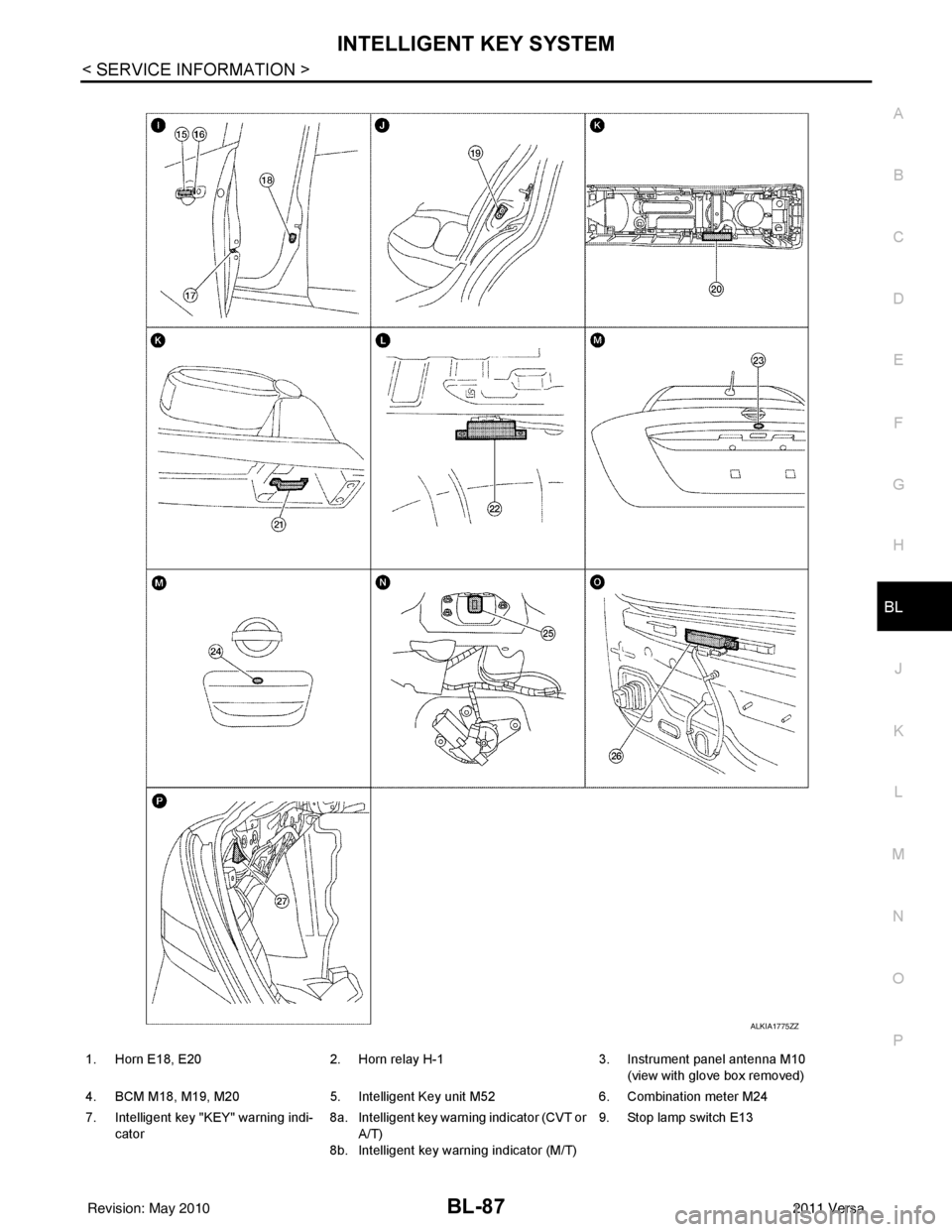
1. Horn E18, E20 2. Horn relay H-1 3. Instrument panel antenna M10
(view with glove box removed)
4. BCM M18, M19, M20 5. Intelligent Key unit M52 6. Combination meter M24
7. Intelligent key "KEY" warning indi- cator 8a.
8b.Intelligent key warning indicator (CVT or
A/T)
Intelligent key warning indicator (M/T) 9. Stop lamp switch E13
Revision: May 2010
2011 Versa
Page 598 of 3787

BL-88
< SERVICE INFORMATION >
INTELLIGENT KEY SYSTEM
System Description
INFOID:0000000005929328
• The Intelligent Key system is a system that makes it possible to lock and unlock the door locks (door lock/
unlock function), and start the engine (engine start func tion) by carrying around the Intelligent Key (without
some key operation), which operates based on the results of electronic ID verification using two-way com-
munications between the Intelligent Key and the vehicle (Intelligent Key unit).
• Vehicles equipped with a manual transmission include a key interlock solenoid located in the steering col- umn to prevent accidental shut-off of the ignition sw itch and locking of the steering wheel during driving con-
dition when the vehicle is moving.
CAUTION:
The driver should always carry the Intelligent Key
• Operation of the remote controller buttons on the Inte lligent Key also provides the same functions as the
remote control entry system. (Remote keyless entry functions)
• If an action that does not meet the operating conditions of the Intelligent Key system is taken, the buzzer
goes off to inform the driver. (Warning chime functions)
• When a door lock is locked or unlocked with request switch or remote controller button operation, the hazard
lamps flash and the buzzer (outside vehicle) sounds (Hazard and buzzer reminder function).
• Even if the Intelligent Key battery is completely discharged, the door locks can be locked and unlocked and the engine started with the mechanical key built into the Intelligent Key.
• The settings for each function can be changed with the CONSULT-III.
• If an Intelligent Key is lost, a new Intelligent Key can be registered. A maximum of 4 Intelligent Keys can be registered.
• It has been made possible to diagnose the system and r egister an Intelligent Key with the CONSULT-III.
DOOR LOCK/UNLOCK FUNCTION
Only when pressing the request switch, it is possible to lock and unlock the door by carrying around the Intelli-
gent Key (without some key operation).
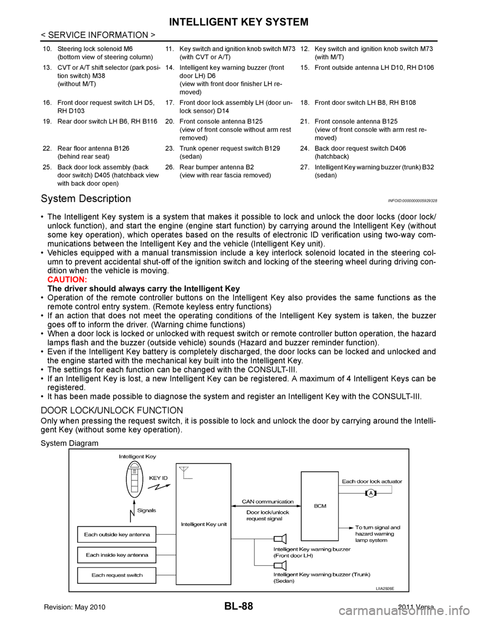
System Diagram
10. Steering lock solenoid M6
(bottom view of steering column) 11. Key switch and ignition knob switch M73
(with CVT or A/T) 12. Key switch and ignition knob switch M73
(with M/T)
13. CVT or A/T shift selector (park posi- tion switch) M38
(without M/T) 14. Intelligent key warning buzzer (front
door LH) D6
(view with front door finisher LH re-
moved) 15. Front outside antenna LH D10, RH D106
16. Front door request switch LH D5, RH D103 17. Front door lock assembly LH (door un-
lock sensor) D14 18. Front door switch LH B8, RH B108
19. Rear door switch LH B6, RH B116 20. Front console antenna B125 (view of front console without arm rest
removed)21. Front console antenna B125
(view of front console with arm rest re-
moved)
22. Rear floor antenna B126 (behind rear seat) 23. Trunk opener request switch B129
(sedan) 24. Back door request switch D406
(hatchback)
25. Back door lock assembly (back door switch) D405 (hatchback view
with back door open) 26. Rear bumper antenna B2
(view with rear fascia removed) 27. Intelligent Key warn
ing buzzer (trunk) B32
(sedan)
LIIA2926E
Revision: May 2010 2011 Versa
Page 603 of 3787

INTELLIGENT KEY SYSTEMBL-93
< SERVICE INFORMATION >
C
DE
F
G H
J
K L
M A
B
BL
N
O P
Even if Intelligent Key battery runs down, Intelligent key unit can start engine with mechanical key built Intelli-
gent Key. For details, refer toBL-246
.
All of the originally supplied Intelligent Key IDs (exc ept for key) have been registered in Intelligent Key system.
If requested by the vehicle owner, a maximum of four Intelligent Key IDs can be registered into the Intelligent
Key system components.
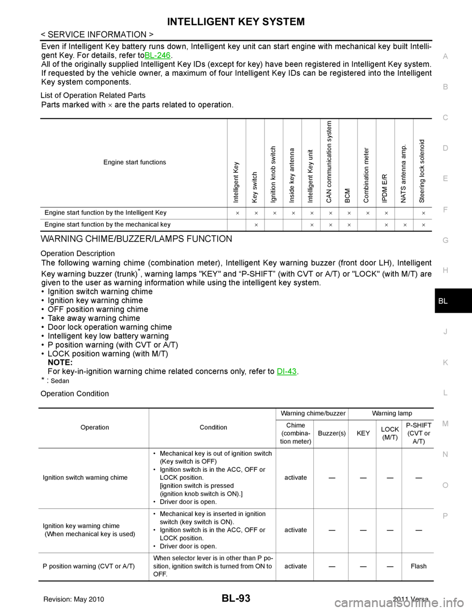
List of Operation Related Parts
Parts marked with × are the parts related to operation.
WARNING CHIME/BUZZER/LAMPS FUNCTION
Operation Description
The following warning chime (combination meter), Intelligent Key warning buzzer (front door LH), Intelligent
Key warning buzzer (trunk)
*, warning lamps "KEY" and “P-SHIFT” (with CVT or A/T) or "LOCK" (with M/T) are
given to the user as warning informati on while using the intelligent key system.
• Ignition switch warning chime
• Ignition key warning chime
• OFF position warning chime
• Take away warning chime
• Door lock operation warning chime
• Intelligent key low battery warning
• P position warning (with CVT or A/T)
• LOCK position warning (with M/T) NOTE:
For key-in-ignition warning chime related concerns only, refer to DI-43
.
* :
Sedan
Operation Condition
Engine start functions
Intelligent Key
Key switch
Ignition knob switch
Inside key antenna
Intelligent Key unit
CAN communication system
BCM
Combination meter
IPDM E/R
NATS antenna amp.
Steering lock solenoid
Engine start function by the Intelligent Key ××××××××× ×
Engine start function by the mechanical key ×××× ×××
Operation ConditionWarning chime/buzzer Warning lamp
Chime
(combina-
tion meter) Buzzer(s) KEY
LOCK
(M/T) P-SHIFT
(CVT or A/T)
Ignition switch warning chime • Mechanical key is out of ignition switch
(Key switch is OFF)
• Ignition switch is in the ACC, OFF or LOCK position.
[ignition switch is pressed
(ignition knob switch is ON).]
• Driver door is open. activate — — — —
Ignition key warning chime
(When mechanical key is used) • Mechanical key is inserted in ignition
switch (key switch is ON).
• Ignition switch is in the ACC, OFF or
LOCK position.
• Driver door is open. activate — — — —
P position warning (CVT or A/T) When selector lever is in other than P po-
sition, ignition switch is turned from ON to
OFF. activate — — — Flash
Revision: May 2010
2011 Versa