2011 NISSAN TIIDA cvt
[x] Cancel search: cvtPage 604 of 3787

BL-94
< SERVICE INFORMATION >
INTELLIGENT KEY SYSTEM
List of Operation Related Parts
Parts marked with × are the parts related to operation.
OFF position warn-
ing chime For internal• Ignition switch is turned from ACC to
OFF.
[ignition switch is pressed (ignition knob
switch is ON).]
• Ignition switch is in the LOCK position and pressed for 1 second. activate — — Flash —
For external When driver door is opened and then
closed while the OFF position warning
chime above is operating —activate—— —
Ta k e a w a y w a r n i n g Right after
door is closed
Right after door is closed and the following
conditions are met.
• Ignition knob is pressed and in rotatable
or rotated state
• Intelligent Key can not be detected in-
side the vehicle —activate
Flash
(red) ——
Any door is
opened Any door is opened and the following con-
ditions are met.
• Ignition knob is pressed and in rotatable
or rotated state
• Intelligent Key unit will perform key ID verification with Intelligent Key through
inside key antenna every 5 second, if
the key ID verification is NG. ——
Flash
(red) ——
Ta k e a w a y
from the win-
dow Take away from the window and the fol-
lowing conditions are met.
• Ignition knob is pressed and in rotatable
or rotated state
• Vehicle speed below 5 km/h (3 m.p.h.)
• Intelligent Key unit will perform key ID
verification with Intelligent Key through
inside key antenna every 30 second, if
the key ID verification is NG.
(This warning function will be disabled if
mechanical key is inserted into the key
cylinder.)
NOTE:
Default setting of this function is OFF. activate —
Flash
(red) ——
Door lock opera-
tion warning Lock opera-
tion with re-
quest switchLock operation with request switch and
the following condition is met.
• Intelligent Key is inside the vehicle
—activate—— —
Intelligent Key low battery warning When Intelligent Key is low battery, Intelli-
gent Key unit is detected after ignition
switch is turned ON.
——
Flash
(green) ——
Operation
ConditionWarning chime/buzzer Warning lamp
Chime
(combina-
tion meter) Buzzer(s) KEY
LOCK
(M/T) P-SHIFT
(CVT or
A/T)
Revision: May 2010 2011 Versa
Page 618 of 3787
BL-108
< SERVICE INFORMATION >
INTELLIGENT KEY SYSTEM
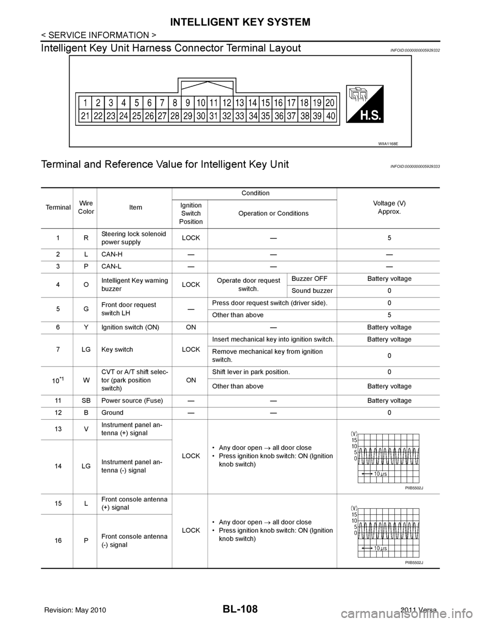
Intelligent Key Unit Harnes s Connector Terminal Layout
INFOID:0000000005929332
Terminal and Reference Value for Intelligent Key UnitINFOID:0000000005929333
WIIA1168E
Te r m i n a lWire
Color Item Condition
Voltage (V)Approx.
Ignition
Switch
Position Operation or Conditions
1R Steering lock solenoid
power supply LOCK
— 5
2 L CAN-H —— —
3 P CAN-L —— —
4O Intelligent Key warning
buzzer LOCK
Operate door request
switch. Buzzer OFF
Battery voltage
Sound buzzer 0
5G Front door request
switch LH —Press door request switch (driver side).
0
Other than above 5
6 Y Ignition switch (ON) ON —Battery voltage
7 LG Key switch LOCKInsert mechanical key into ignition switch. Battery voltage
Remove mechanical key from ignition
switch.
0
10
*1W CVT or A/T shift selec-
tor (park position
switch)
ONShift lever in park position.
0
Other than above Battery voltage
11 SB Power source (Fuse) — —Battery voltage
12 B Ground —— 0
13 V Instrument panel an-
tenna (+) signal
LOCK• Any door open
→ all door close
• Press ignition knob switch: ON (Ignition knob switch)
14 LG Instrument panel an-
tenna (-) signal
15 L Front console antenna
(+) signal
LOCK• Any door open
→ all door close
• Press ignition knob switch: ON (Ignition knob switch)
16 P Front console antenna
(-) signal
PIIB5502J
PIIB5502J
Revision: May 2010
2011 Versa
Page 620 of 3787
BL-110
< SERVICE INFORMATION >
INTELLIGENT KEY SYSTEM
*1: With continuously variable transmission (CVT) or automatic transmission (A/T).
*2: With manual transmission (M/T).
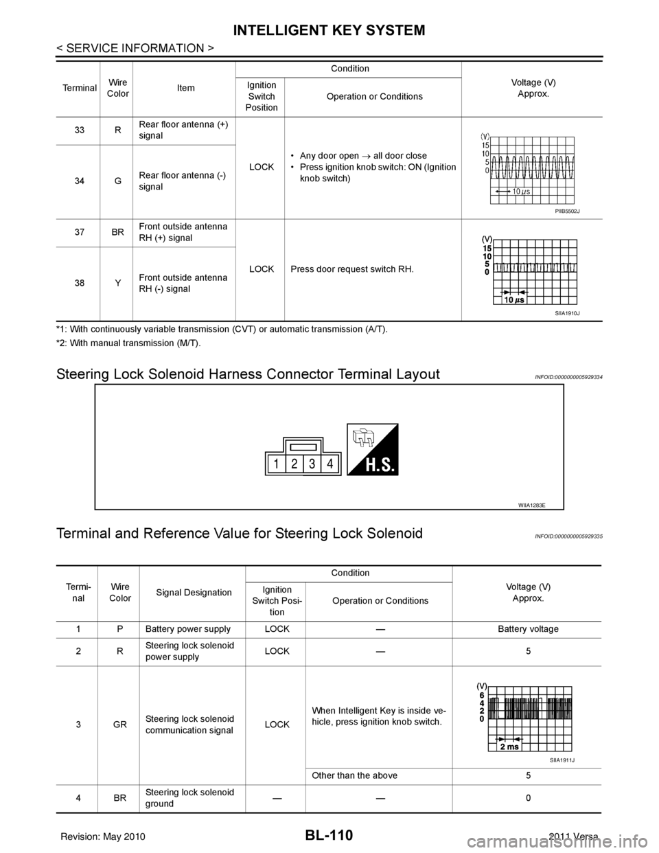
Steering Lock Solenoid Harn ess Connector Terminal LayoutINFOID:0000000005929334
Terminal and Reference Valu e for Steering Lock SolenoidINFOID:0000000005929335
33 RRear floor antenna (+)
signal
LOCK• Any door open
→ all door close
• Press ignition knob switch: ON (Ignition knob switch)
34 G Rear floor antenna (-)
signal
37 BR Front outside antenna
RH (+) signal
LOCK Press door request switch RH.
38 Y Front outside antenna
RH (-) signal
Te r m i n a l
Wire
Color Item Condition
Voltage (V)Approx.
Ignition
Switch
Position Operation or Conditions
PIIB5502J
SIIA1910J
WIIA1283E
Te r m i -
nal Wire
Color Signal Designation Condition
Voltage (V)Approx.
Ignition
Switch Posi- tion Operation or Conditions
1 P Battery power supply LOCK —Battery voltage
2R Steering lock solenoid
power supply LOCK
— 5
3GR Steering lock solenoid
communication signal
LOCKWhen Intelligent Key is inside ve-
hicle, press ignition knob switch.
Other than the above
5
4BR Steering lock solenoid
ground ——
0
SIIA1911J
Revision: May 2010 2011 Versa
Page 631 of 3787

INTELLIGENT KEY SYSTEMBL-121
< SERVICE INFORMATION >
C
DE
F
G H
J
K L
M A
B
BL
N
O P
NON-DTC ITEM
NOTE:
• Before performing the diagnosis in the following table, check “Trouble Diagnosis Procedure”. Refer to BL-
115, "Trouble Diagnosis Procedure".
• Make sure that vehicle is under the condition shown in “Conditions of vehicle” before starting diagnosis, and
check each symptom.
• If the following “symptoms” are detected, check syst ems shown in the “Diagnoses/service procedure” col-
umn in this order.
Conditions of Vehicle (Operating Conditions)
• Intelligent Key is registered.
• Multiple mechanical keys are not set in a keyfob. (If mechanical keys are near the ignition switch, the operation may not work properly.)
ENGINE START CONDITION CHECK
NOTE:
• Before performing the diagnosis in the following table, check “Trouble Diagnosis Procedure”. Refer to BL-
115, "Trouble Diagnosis Procedure".
• If the following “symptoms” are detected, check syst ems shown in the ”Diagnoses/service procedure” col-
umn in this order.
ALL FUNCTIONS OF INTELLIGENT KEY SYSTEM DO NOT OPERATE
NOTE:
• Before performing the diagnosis in the following table, check “Trouble Diagnosis Procedure”. Refer to BL-
115, "Trouble Diagnosis Procedure".
• Make sure that vehicle is under the condition shown in “Conditions of vehicle” before starting diagnosis, and
check each symptom.
• If the following “symptoms” are detected, check syst ems shown in the “Diagnosis/service procedure” column
in this order.
Conditions of Vehicle (Operating Conditions)
• “ENGINE START BY I-KEY” and “LOCK/UNLOCK BY I-KEY” are ON when setting on CONSULT-III.
• Mechanical key is out of ignition switch.
• Ignition switch is not depressed.
• All doors are closed.
• Intelligent key is registered.
RED key warning lamp does not illuminate
[Without Intelligent Key]. 1. Check "KEY" warning lamp (RED).
BL-155
2. Replace Intelligent Key unit.BL-158
SymptomDiagnosis/service procedureReference page
SymptomDiagnosis/service procedure Reference page
Non DTC Item 1. Check key switch.
BL-127
2. Check NATS antenna amp.BL-246
SymptomDiagnosis/service procedure Reference page
Engine start condition check 1. Check CVT or A/T shift selector (park position switch).
(with CVT or A/T) BL-153
2. Check key interlock solenoid (with M/T).
BL-149
3. Check stop lamp switch (with CVT or A/T).BL-150
4. Check stop lamp switch (with M/T).BL-152
Revision: May 2010 2011 Versa
Page 636 of 3787

BL-126
< SERVICE INFORMATION >
INTELLIGENT KEY SYSTEM
CAN Communication System Inspection
INFOID:0000000005929341
1.CHECK SELF-DIAGNOSTIC RESULTS
With CONSULT-III
• Connect CONSULT-III, and turn ignition switch ON.
• Touch “INTELLIGENT KEY” on “SELECT SYSTEM” screen.
• Touch “SELF-DIAG RESULTS” on “SELECT DIAG MODE” screen.
• Check display content in self-diagnostic results.
OK or NG
NO DTC IS DETECT ED>> Inspection End.
CAN COMM [U1000]>> After printing “SELF-DIAGNOSI S RESULTS”, go to “CAN SYSTEM”. Refer to LAN-
17, "Trouble Diagnosis Flow Chart".
CAN COMM2 [U1010] >> Replace Intelligent Key unit. Refer to BL-158, "
Removal and Installation of Intelli-
gent Key Unit".
Power Supply and Ground Circuit InspectionINFOID:0000000005929342
1.CHECK POWER SUPPLY CIRCUIT
1. Turn ignition switch OFF.
2. Disconnect Intelligent Key unit connector.
3. Check voltage between Intelligent Key unit harness connector and ground.
Symptom Diagnosis/service procedureReference page
When Intelligent Key low batt ery warning operate, “KEY”
warning lamp (green) does not illuminate. 1.
Check “LOW BAT OF KEY FOB WARN” setting
in “WORK SUPPORT”. BL-117
2. Check Intelligent Key battery.
BL-158
3. Check KEY warning lamp (green).BL-155
4. Replace Intelligent Key unit.BL-158
P position warning lamp does not illuminate properly.
(With CVT or A/T)1.
Check CVT or A/T shift selector (park position
switch). BL-153
2. Check “P-SHIFT” warning lamp (red).
BL-154
3. Replace Intelligent Key unit.BL-158
LOCK warning lamp does not illuminate properly.
(With M/T)1. Check key interlock solenoid.
BL-1492. Check "LOCK" warning lamp.BL-155
3. Replace Intelligent Key unit.BL-158
Take away warning lamp does not illuminate properly.
(Take away warning chime is operated).1. Check KEY warning lamp (red).
BL-158
2. Replace Intelligent Key unit.BL-158
Ignition switch warning lamp does not illuminate properly.
(Ignition switch warning chime is operated).1. Check KEY warning lamp (red).
BL-155
2. Replace Intelligent Key unit.BL-158
CONSULT-III display item DTC code
NO DTC IS DETECTED —
CAN COMM U1000
CAN COMM2 U1010
Revision: May 2010 2011 Versa
Page 660 of 3787
BL-150
< SERVICE INFORMATION >
INTELLIGENT KEY SYSTEM
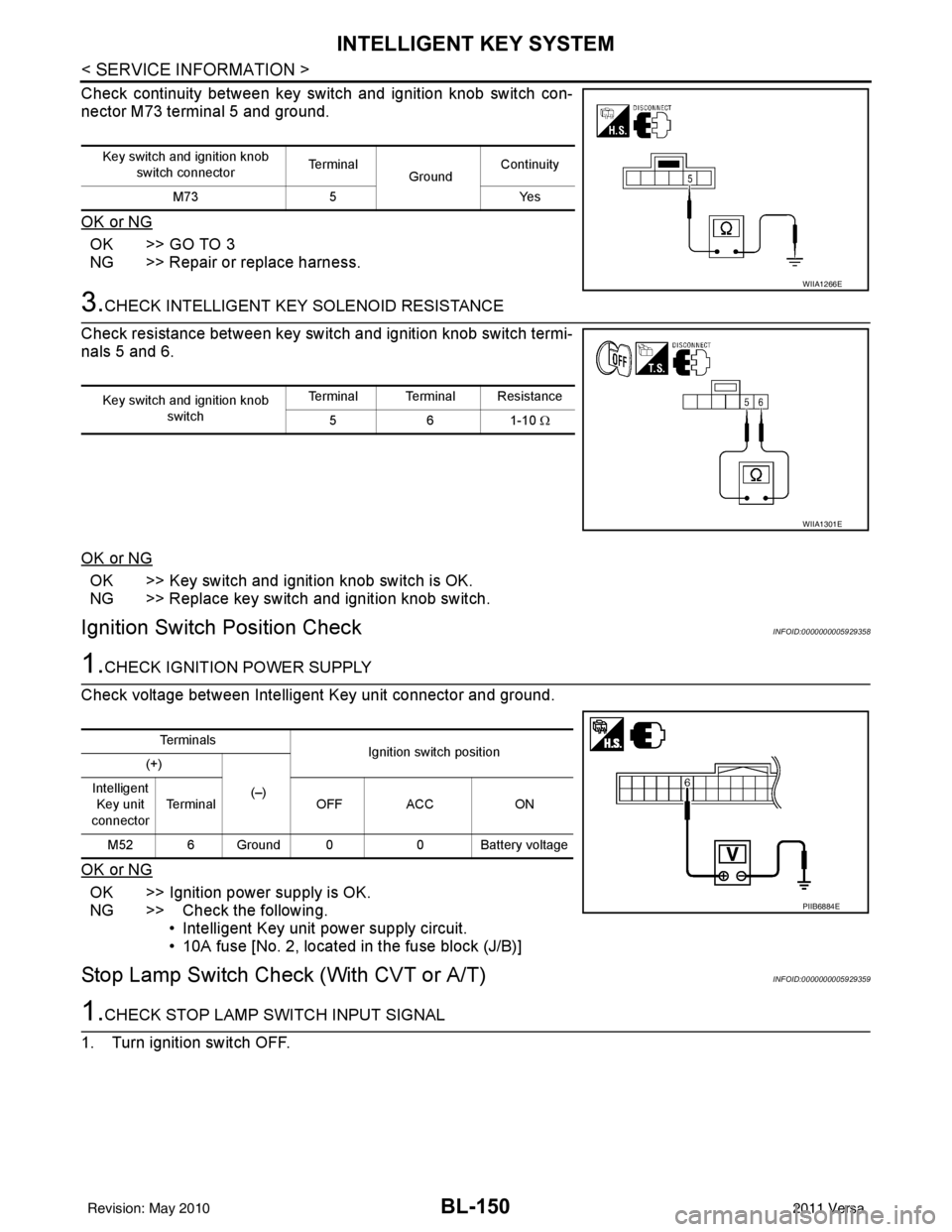
Check continuity between key switch and ignition knob switch con-
nector M73 terminal 5 and ground.
OK or NG
OK >> GO TO 3
NG >> Repair or replace harness.
3.CHECK INTELLIGENT KEY SOLENOID RESISTANCE
Check resistance between key switch and ignition knob switch termi-
nals 5 and 6.
OK or NG
OK >> Key switch and ignition knob switch is OK.
NG >> Replace key switch and ignition knob switch.
Ignition Switch Position CheckINFOID:0000000005929358
1.CHECK IGNITION POWER SUPPLY
Check voltage between Intelligent Key unit connector and ground.
OK or NG
OK >> Ignition power supply is OK.
NG >> Check the following. • Intelligent Key unit power supply circuit.
• 10A fuse [No. 2, located in the fuse block (J/B)]
Stop Lamp Switch Check (With CVT or A/T)INFOID:0000000005929359
1.CHECK STOP LAMP SWITCH INPUT SIGNAL
1. Turn ignition switch OFF.
Key switch and ignition knob switch connector Te r m i n a l
GroundContinuity
M73 5 Yes
WIIA1266E
Key switch and ignition knob
switch Terminal Terminal Resistance
561-10 Ω
WIIA1301E
Te r m i n a l s
Ignition switch position
(+)
(–)
Intelligent
Key unit
connector Terminal
OFF ACC ON
M52 6 Ground 0 0 Battery voltage
PIIB6884E
Revision: May 2010 2011 Versa
Page 663 of 3787
INTELLIGENT KEY SYSTEMBL-153
< SERVICE INFORMATION >
C
DE
F
G H
J
K L
M A
B
BL
N
O P
OK >> Check condition of harness and connector.
NG >> Repair or replace harness.
CVT or A/T Shift Se lector (Park Position Switch) CheckINFOID:0000000005929361
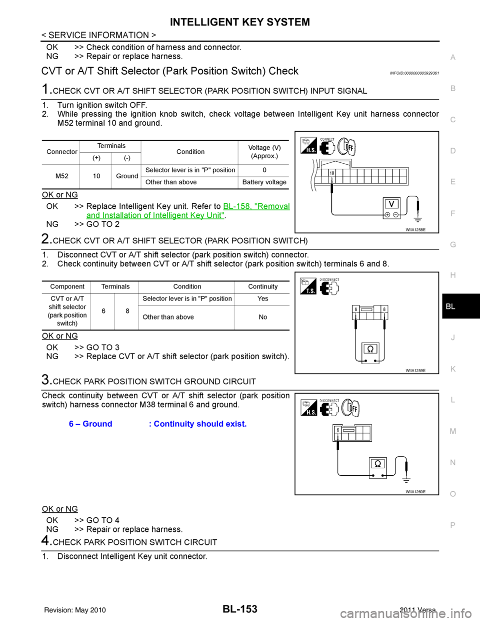
1.CHECK CVT OR A/T SHIFT SELECTOR (PARK POSITION SWITCH) INPUT SIGNAL
1. Turn ignition switch OFF.
2. While pressing the ignition knob switch, check voltage between Intelligent Key unit harness connector M52 terminal 10 and ground.
OK or NG
OK >> Replace Intelligent Key unit. Refer to BL-158, "Removal
and Installation of Intelligent Key Unit".
NG >> GO TO 2
2.CHECK CVT OR A/T SHIFT SELECTOR (PARK POSITION SWITCH)
1. Disconnect CVT or A/T shift select or (park position switch) connector.
2. Check continuity between CVT or A/T shift selector (park position switch) terminals 6 and 8.
OK or NG
OK >> GO TO 3
NG >> Replace CVT or A/T shift selector (park position switch).
3.CHECK PARK POSITION SWITCH GROUND CIRCUIT
Check continuity between CVT or A/T shift selector (park position
switch) harness connector M38 terminal 6 and ground.
OK or NG
OK >> GO TO 4
NG >> Repair or replace harness.
4.CHECK PARK POSITION SWITCH CIRCUIT
1. Disconnect Intelligent Key unit connector.
Connector Te r m i n a l s
ConditionVoltage (V)
(Approx.)
(+) (-)
M52 10 Ground Selector lever is in "P" position 0
Other than above
Battery voltage
WIIA1258E
Component Terminals ConditionContinuity
CVT or A/T
shift selector
(park position switch) 68Selector lever is in "P" position Yes
Other than above
No
WIIA1259E
6 – Ground : Continuity should exist.
WIIA1260E
Revision: May 2010 2011 Versa
Page 664 of 3787
BL-154
< SERVICE INFORMATION >
INTELLIGENT KEY SYSTEM
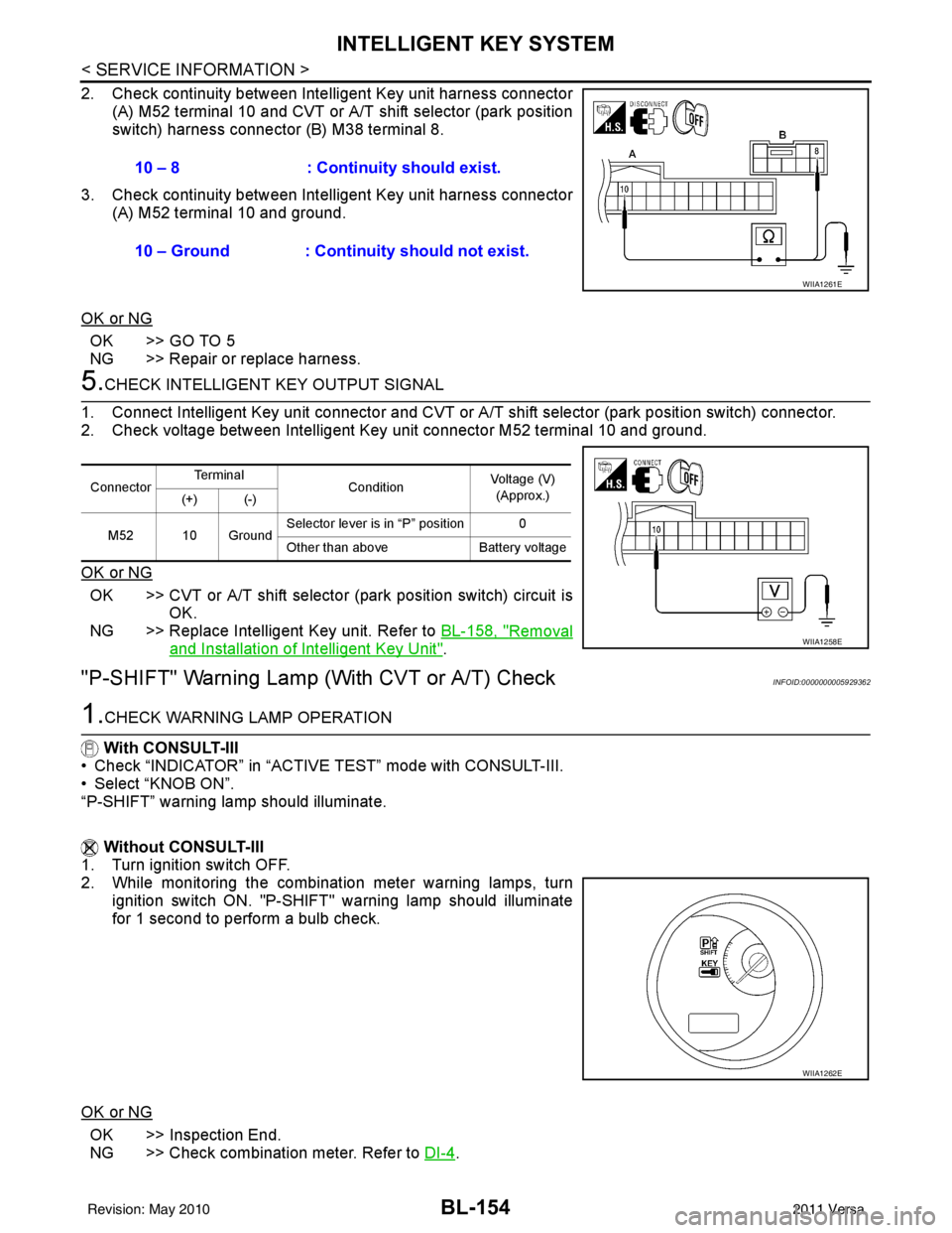
2. Check continuity between Intelligent Key unit harness connector
(A) M52 terminal 10 and CVT or A/T shift selector (park position
switch) harness connector (B) M38 terminal 8.
3. Check continuity between Inte lligent Key unit harness connector
(A) M52 terminal 10 and ground.
OK or NG
OK >> GO TO 5
NG >> Repair or replace harness.
5.CHECK INTELLIGENT KEY OUTPUT SIGNAL
1. Connect Intelligent Key unit connector and CVT or A/T shift selector (park position switch) connector.
2. Check voltage between Intelligent Key unit connector M52 terminal 10 and ground.
OK or NG
OK >> CVT or A/T shift selector (park position switch) circuit is
OK.
NG >> Replace Intelligent Key unit. Refer to BL-158, "
Removal
and Installation of Intelligent Key Unit".
"P-SHIFT" Warning Lamp (With CVT or A/T) CheckINFOID:0000000005929362
1.CHECK WARNING LAMP OPERATION
With CONSULT-III
• Check “INDICATOR” in “ACTIVE TEST” mode with CONSULT-III.
• Select “KNOB ON”.
“P-SHIFT” warning lamp should illuminate.
Without CONSULT-III
1. Turn ignition switch OFF.
2. While monitoring the combination meter warning lamps, turn
ignition switch ON. "P-SHIFT" warning lamp should illuminate
for 1 second to perform a bulb check.
OK or NG
OK >> Inspection End.
NG >> Check combination meter. Refer to DI-4
.
10 – 8 : Continuity should exist.
10 – Ground : Continuity should not exist.
WIIA1261E
Connector
Te r m i n a l
ConditionVoltage (V)
(Approx.)
(+) (-)
M52 10 Ground Selector lever is in “P” position 0
Other than above
Battery voltage
WIIA1258E
WIIA1262E
Revision: May 2010 2011 Versa