2011 NISSAN TIIDA rear air control
[x] Cancel search: rear air controlPage 1 of 3787

-1
QUICK REFERENCE INDEX
AGENERAL INFORMATIONGIGeneral Information
BENGINEEMEngine Mechanical
LUEngine Lubrication System
COEngine Cooling System
ECEngine Control System
FLFuel System
EXExhaust System
ACCAccelerator Control System
CTRANSMISSION/
TRANSAXLECLClutch System
MTManual Transaxle
ATAutomatic Transaxle
CVTCVT
DDRIVELINE/AXLEFAXFront Axle
RAXRear Axle
ESUSPENSIONFSUFront Suspension
RSURear Suspension
WTRoad Wheels & Tires
FBRAKESBRBrake System
PBParking Brake System
BRCBrake Control System
GSTEERINGPSPower Steering System
STCSteering Control System
HRESTRAINTSSBSeat Belts
SRSSupplemental Restraint System (SRS)
IBODYBLBody, Lock & Security System
GWGlasses, Window System & Mirrors
RFRoof
EIExterior & Interior
IPInstrument Panel
SESeat
JAIR CONDITIONERMTCManual Air Conditioner
KELECTRICALSCStarting & Charging System
LTLighting System
DIDriver Information System
WWWiper, Washer & Horn
BCSBody Control System
LANLAN System
AVAudio Visual, Navigation & Telephone System
ACSAuto Cruise Control System
PGPower Supply, Ground & Circuit Elements
LMAINTENANCEMAMaintenance
Edition: May 2010
Revision: May 2010
Publication No. SM1E-1C11U0
B
D
© 2010 NISSAN NORTH AMERICA, INC.
All rights reserved. No part of this Service Manual may be reproduced or stored in a retrieval system, or transmitted in any
form, or by any means, electronic, mechanical, photo-copying, recording or otherwise, without the prior written permission
of Nissan North America Inc.
A
C
E
F
G
H
I
J
K
L
M
Page 21 of 3787

AT-4
Transmission Range Switch ..................................225
Output Speed Sensor ............................................227
Input Speed Sensor ...............................................228
Differential Side Oil Seal ........................................229
AIR BREATHER HOSE ...................................232
Removal and Installation ..................................... ..232
TRANSAXLE ASSEMBLY ..............................233
Removal and Installation ..................................... ..233
OVERHAUL .................................................... .237
Component .......................................................... ..237
Oil Channel ............................................................250
Location of Adjusting Shims, Needle Bearings and
Thrust Washers .....................................................
253
Location of Snap Rings .........................................255
DISASSEMBLY .............................................. .257
Disassembly ........................................................ ..257
REPAIR FOR COMPONENT PARTS ..............275
Manual Shaft ....................................................... ..275
Oil Pump ................................................................278
Control Valve Assembly ........................................281
Control Valve Upper Body .....................................290
Control Valve Lower Body ................................... ..294
Reverse Clutch ......................................................297
High Clutch ............................................................302
Forward and Overrun Clutches .............................307
Low & Reverse Brake ............................................314
Rear Internal Gear and Forward Clutch Hub .........318
Output Shaft, Output Gear, Idler Gear, Reduction
Pinion Gear and Bearing Retainer .........................
322
Band Servo Piston Assembly ................................331
Final Drive .............................................................337
ASSEMBLY .....................................................344
Assembly (1) ........................................................ ..344
Adjustment (1) (For HR16DE Engine Models) ..... .345
Adjustment (1) (For MR18DE Engine Models) .....349
Assembly (2) .........................................................355
Adjustment (2) .......................................................360
Assembly (3) .........................................................363
SERVICE DATA AND SPECIFICATIONS
(SDS) ................................................................
373
General Specification ........................................... .373
Vehicle Speed at Which Gear Shifting Occurs .....373
Vehicle Speed at When Lock-up Occurs/Releases
.
373
Stall Speed ............................................................374
Line Pressure ........................................................374
Adjusting shims, Needle Bearings, Thrust Wash-
ers and Snap Rings ..............................................
374
Control Valves .......................................................375
Accumulator ..........................................................376
Clutches and Brakes .............................................376
Final Drive .............................................................378
Planetary Carrier ...................................................378
Oil Pump ...............................................................378
Input Shaft .............................................................378
Reduction Pinion Gear ..........................................378
Band Servo ...........................................................378
Output Shaft ..........................................................379
Bearing Retainer ...................................................379
Total End Play ...................................................... .379
Reverse Clutch End Play ......................................379
Removal and Installation .......................................379
Shift Solenoid Valves ........................................... .379
Solenoid Valves ....................................................380
A/T Fluid Temperature Sensor ..............................380
Output Speed Sensor ...........................................380
Dropping Resistor .................................................380
Input Speed Sensor ..............................................380
Revision: May 2010 2011 Versa
Page 204 of 3787

TROUBLE DIAGNOSIS FOR SYMPTOMSAT-187
< SERVICE INFORMATION >
DE
F
G H
I
J
K L
M A
B
AT
N
O P
NG >> GO TO 3.
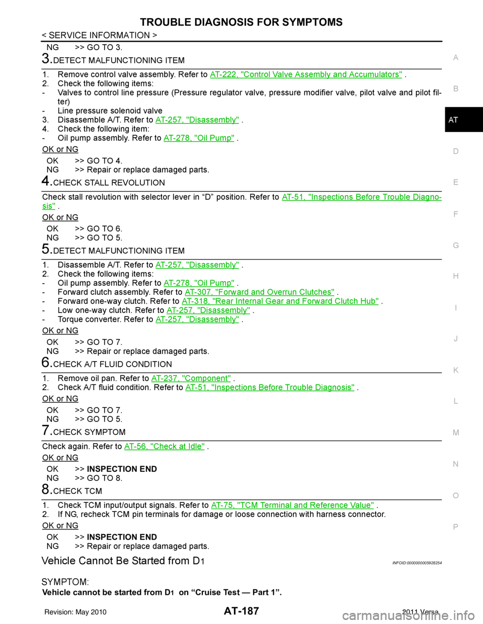
3.DETECT MALFUNCTIONING ITEM
1. Remove control valve assembly. Refer to AT-222, "
Control Valve Assembly and Accumulators" .
2. Check the following items:
- Valves to control line pressure (Pressure regulator valv e, pressure modifier valve, pilot valve and pilot fil-
ter)
- Line pressure solenoid valve
3. Disassemble A/T. Refer to AT-257, "
Disassembly" .
4. Check the following item:
- Oil pump assembly. Refer to AT-278, "
Oil Pump" .
OK or NG
OK >> GO TO 4.
NG >> Repair or replace damaged parts.
4.CHECK STALL REVOLUTION
Check stall revolution with selector lever in “D” position. Refer to AT-51, "
Inspections Before Trouble Diagno-
sis" .
OK or NG
OK >> GO TO 6.
NG >> GO TO 5.
5.DETECT MALFUNCTIONING ITEM
1. Disassemble A/T. Refer to AT-257, "
Disassembly" .
2. Check the following items:
- Oil pump assembly. Refer to AT-278, "
Oil Pump" .
- Forward clutch assembly. Refer to AT-307, "
Forward and Overrun Clutches" .
- Forward one-way clutch. Refer to AT-318, "
Rear Internal Gear and Forward Clutch Hub" .
- Low one-way clutch. Refer to AT-257, "
Disassembly" .
- Torque converter. Refer to AT-257, "
Disassembly" .
OK or NG
OK >> GO TO 7.
NG >> Repair or replace damaged parts.
6.CHECK A/T FLUID CONDITION
1. Remove oil pan. Refer to AT-237, "
Component" .
2. Check A/T fluid condition. Refer to AT-51, "
Inspections Before Trouble Diagnosis" .
OK or NG
OK >> GO TO 7.
NG >> GO TO 5.
7.CHECK SYMPTOM
Check again. Refer to AT-56, "
Check at Idle" .
OK or NG
OK >> INSPECTION END
NG >> GO TO 8.
8.CHECK TCM
1. Check TCM input/output signals. Refer to AT-75, "
TCM Terminal and Reference Value" .
2. If NG, recheck TCM pin terminals for dam age or loose connection with harness connector.
OK or NG
OK >> INSPECTION END
NG >> Repair or replace damaged parts.
Vehicle Cannot Be Started from D1INFOID:0000000005928254
SYMPTOM:
Vehicle cannot be started from D1 on “Cruise Test — Part 1”.
Revision: May 2010 2011 Versa
Page 205 of 3787

AT-188
< SERVICE INFORMATION >
TROUBLE DIAGNOSIS FOR SYMPTOMS
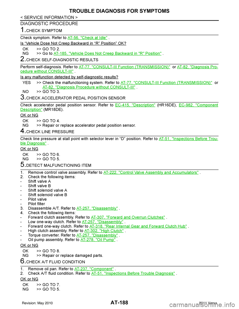
DIAGNOSTIC PROCEDURE
1.CHECK SYMPTOM
Check symptom. Refer to AT-56, "
Check at Idle" .
Is
“Vehicle Dose Not Creep Backward in “R” Position” OK?
OK >> GO TO 2.
NG >> Go to AT-185, "
Vehicle Does Not Creep Backward in "R" Position" .
2.CHECK SELF-DIAGNOSTIC RESULTS
Perform self-diagnosis. Refer to AT-77, "
CONSULT-III Function (TRANSMISSION)" or AT-82, "Diagnosis Pro-
cedure without CONSULT-III" .
Is any malfunction detected by self-diagnostic results?
YES >> Check the malfunctioning system. Refer to AT-77, "CONSULT-III Function (TRANSMISSION)" or
AT-82, "
Diagnosis Procedure without CONSULT-III" .
NO >> GO TO 3.
3.CHECK ACCELERATOR PEDAL POSITION SENSOR
Check accelerator pedal position sensor. Refer to EC-415, "
Description" (HR16DE), EC-982, "Component
Description" (MR18DE).
OK or NG
OK >> GO TO 4.
NG >> Repair or replace accelerator pedal position sensor.
4.CHECK LINE PRESSURE
Check line pressure at stall point with selector lever in “D” position. Refer to AT-51, "
Inspections Before Trou-
ble Diagnosis" .
OK or NG
OK >> GO TO 6.
NG >> GO TO 5.
5.DETECT MALFUNCTIONING ITEM
1. Remove control valve assembly. Refer to AT-222, "
Control Valve Assembly and Accumulators" .
2. Check the following items:
- Shift valve A
- Shift valve B
- Shift solenoid valve A
- Shift solenoid valve B
- Pilot valve
- Pilot filter
3. Disassemble A/T. Refer to AT-257, "
Disassembly" .
4. Check the following items:
- Forward clutch assembly. Refer to AT-307, "
Forward and Overrun Clutches" .
- Low one-way clutch. Refer to AT-257, "
Disassembly" .
- Forward one-way clutch. Refer to AT-318, "
Rear Internal Gear and Forward Clutch Hub" .
- High clutch assembly. Refer to AT-302, "
High Clutch" .
- Torque converter. Refer to AT-257, "
Disassembly" .
- Oil pump assembly. Refer to AT-278, "
Oil Pump" .
OK or NG
OK >> GO TO 8.
NG >> Repair or replace damaged parts.
6.CHECK A/T FLUID CONDITION
1. Remove oil pan. Refer to AT-237, "
Component" .
2. Check A/T fluid condition. Refer to AT-51, "
Inspections Before Trouble Diagnosis" .
OK or NG
OK >> GO TO 7.
NG >> GO TO 5.
Revision: May 2010 2011 Versa
Page 398 of 3787

AV-1
ELECTRICAL
C
DE
F
G H
I
J
L
M
SECTION AV
A
B
AV
N
O P
CONTENTS
AUDIO, VISUAL, NAVIGATION & TELEPHONE SYS- TEM
AUDIO WITHOUT NAVIGATION
SERVICE INFORMATION .. ..........................
3
PRECAUTIONS .............................................. .....3
Precaution for Supplemental Restraint System
(SRS) "AIR BAG" and "SEAT BELT PRE-TEN-
SIONER" ............................................................. ......
3
Precaution Necessary for Steering Wheel Rota-
tion After Battery Disconnect ............................... ......
3
PREPARATION ...................................................5
Commercial Service Tool .................................... ......5
AUDIO .................................................................6
Component Parts Location .................................. ......6
System Description ...................................................6
Schematic .................................................................8
Wiring Diagram - AUDIO - .........................................9
Audio Unit (Base System) Harness Connector
Terminal Layout ......................................................
15
Terminal and Reference Value for Audio Unit
(Base System) .........................................................
15
Audio Unit (Premium System) Harness Connector
Terminal Layout ......................................................
16
Terminal and Reference Value for Audio Unit
(Premium System) ..................................................
16
IPod Adapter Harness Connector Terminal Layout
....
18
Terminal and Reference Value for IPod Adapter ....19
Trouble Diagnosis ...................................................20
Noise Inspection ......................................................21
Power Supply Circuit Inspection .............................22
Steering Switch Check (With Bluetooth) .................22
Sound Is Not Heard from Front Door Speaker
(Base System) .........................................................
24
Sound Is Not Heard from Rear Door Speaker
(Base System) .........................................................
25
Sound Is Not Heard from Front Door Speaker or
Tweeter (Premium System) ....................................
26
Sound Is Not Heard from Rear Door Speaker
(Premium System) ............................................... ....
27
Removal and Installation .........................................29
iPod® CONNECTOR ........................................31
Removal and Installation .........................................31
iPod® ADAPTER ..............................................32
Removal and Installation .........................................32
AUDIO ANTENNA .............................................33
Location of Antenna ............................................. ....33
Removal and Installation of Roof Antenna ..............33
TELEPHONE .....................................................35
Component Parts and Harness Connector Loca-
tion ...........................................................................
35
System Description ..................................................35
Wiring Diagram - H/PHON - ....................................37
Bluetooth Control Unit Harness Connector Termi-
nal Layout ............................................................ ....
39
Terminal and Reference Value for Bluetooth Con-
trol Unit ....................................................................
39
Bluetooth Control Unit Self-Diagnosis Function ......41
Workflow .............................................................. ....41
Power Supply and Ground Circuit Inspection for
Bluetooth Control Unit .............................................
42
Steering Wheel Audio Co ntrol Switch Does Not
Operate ................................................................ ....
43
Voice Activated Control Function Does Not Oper-
ate ........................................................................ ....
43
Removal and Installation .........................................46
AUDIO WITH NAVIGATION
SERVICE INFORMATION .. .........................
50
PRECAUTIONS .................................................50
Precaution for Supplemental Restraint System
(SRS) "AIR BAG" and "SEAT BELT PRE-TEN-
SIONER" ............................................................. ....
50
Precaution Necessary for Steering Wheel Rota-
tion After Battery Disconnect ...................................
50
Revision: May 2010 2011 Versa
Page 469 of 3787
![NISSAN TIIDA 2011 Service Repair Manual AV-72
< SERVICE INFORMATION >[AUDIO WITH NAVIGATION]
AUDIO
4. Check the signal between AV control unit connector terminals
with CONSULT-III or oscilloscope.
OK or NG
OK >> Replace front speaker. Refer NISSAN TIIDA 2011 Service Repair Manual AV-72
< SERVICE INFORMATION >[AUDIO WITH NAVIGATION]
AUDIO
4. Check the signal between AV control unit connector terminals
with CONSULT-III or oscilloscope.
OK or NG
OK >> Replace front speaker. Refer](/manual-img/5/57396/w960_57396-468.png)
AV-72
< SERVICE INFORMATION >[AUDIO WITH NAVIGATION]
AUDIO
4. Check the signal between AV control unit connector terminals
with CONSULT-III or oscilloscope.
OK or NG
OK >> Replace front speaker. Refer to AV-73, "Removal and
Installation".
NG >> Replace AV control unit. Refer to AV-73, "
Removal and
Installation".
Sound Is Not Heard from Rear SpeakerINFOID:0000000006216712
1.HARNESS CHECK
1. Disconnect AV control unit connector and rear speaker connector.
2. Check continuity between AV control unit harness connector ter- minal and rear speaker harness connector terminal.
3. Check continuity between AV control unit harness connector ter- minal and ground.
OK or NG
OK >> GO TO 2.
NG >> • Check connector housings for disconnected or loose terminals. • Repair harness or connector.
2.REAR SPEAKER SIGNAL CHECK
Te r m i n a l s
Condi-tion Reference
signal
(+)
(-)
Con-
nector Te r m i -
nal Con-
nector Te r m i -
nal
M43 2
M43 3
Receive
audio
signal
11
1 2
WKIA5853E
SKIA0177E
Te r m i n a l s
Continuity
AV control unit Speaker
Connector Terminal Connector Terminal
A: M43 4
B: D207 +
Ye s
5-
13 B: D307 +
14 -
Te r m i n a l s Continuity
AV control unit
—
Connector Terminal
A: M43 4
Ground No
5
13
14
WKIA5353E
Revision: May 2010 2011 Versa
Page 498 of 3787

BCS-8
< SERVICE INFORMATION >
BCM (BODY CONTROL MODULE)
CAN Communication System Description
INFOID:0000000005929256
Refer to LAN-7, "System Description".
Panic alarm •Key switch
•KeyfobIPDM E/R
Vehicle security system • All door switches
•Keyfob
• Door lock/unlock switch
• Trunk key cylinder switch (Se-
dan)
• Front door key cylinder switch LH • IPDM/ER
• Security indicator lamp
Battery save r control • Ignition switch
• Combination switch
IPDM E/R
Headlamp Combination switch IPDM E/R
Tail lamp Combination switchIPDM E/R
Front fog lamp (with front fog lamps) Combination switch IPDM E/R
Turn signal lamp Combination switch• Turn signal lamp
• Combination meter
Hazard lamp Hazard switch• Turn signal lamp
• Combination meter
Room lamp timer •Key switch
•Keyfob
• Main power window and door
lock/unlock switch
• Front door switch LH
• All door switch Interior room lamp
Back door switch signal (Hatchback) Back door lock assembly Luggage room lamp
Back door lock signal (Hatchback) Back door lock assembly Back door opener
Trunk lamp switch signal (Sedan) Trunk lamp switch and trunk re-
lease solenoidLuggage room lamp
Trunk lid opener signal (Sedan) Trunk lamp switch and trunk re-
lease solenoid
Trunk lid opener
Key warning chime •Key switch
• Front door switch LHCombination meter (warning buzzer)
Light warning chime • Combination switch
•Key switch
• Front door switch LHCombination meter (warning buzzer)
Seat belt warning chime • Seat belt buckle switch LH
• Ignition switch
Combination meter (warning buzzer)
Front wiper and washer system • Combination switch
• Ignition switchIPDM E/R
Rear window defogger Rear window defogger switch IPDM E/R
Rear wiper and washer system
(Hatchback) • Combination switch
• Ignition switch
Rear wiper motor
A/C switch signal Front air controlECM
Blower fan switch signal Front air controlECM
A/C indicator signal Front air controlA/C indicator
Low tire pressure warning system Remote keyless entry receiver Combination meter System
Input Output
Revision: May 2010 2011 Versa
Page 508 of 3787

BCS-18
< SERVICE INFORMATION >
BCM (BODY CONTROL MODULE)
WORK SUPPORT
Display Item List
CAN Communication Inspection Using CONSULT-III (Self-Diagnosis)INFOID:0000000005929262
1.SELF-DIAGNOSTIC RESULT CHECK
1. Connect CONSULT–III and select “BCM” on “SELECT SYSTEM” screen.
2. Select “BCM” on “SELECT TEST ITEM” screen, and select “SELF-DIAG RESULTS”.
3. Check display content in self-diagnostic results.
System and item CONSULT-III
display Diagnostic test mode (Inspection by part)
WORK
SUPPORT SELF
DIAGNOS- TIC RE-
SULT CAN DIAG
SUPPORT MNTR DATA
MONITOR ECU
IDENTI- FICA-
TION AC-
TIVE
TEST CON-
FIGU-
RATION
BCM BCM×× × × ×
Power door lock sys-
tem DOOR LOCK
×× ×
Rear defogger REAR DEFOG-
GER ××
Warning chime BUZZER ××
Room lamp timer INT LAMP ×× ×
Remote keyless entry
system MULTI REMOTE
ENT
××
×
Headlamp HEAD LAMP×× ×
Wiper WIPER×× ×
Turn signal lamp
Hazard lamp FLASHER
××
Blower fan switch sig-
nal
Air conditioner switch
signal AIR CONDITION-
ER
××
Intelligent Key INTELLIGENT
KEY ×
Combination switch COMB SW ×
NVIS (NATS) IMMU ××
Interior lamp battery
saver BATTERY SAV-
ER
××
×
Back door/Trunk TRUNK ××
Theft alarm THEFT ALARM×× ×
Retained accessory
power control RETAINED PWR
×× ×
Oil pressure swit ch SIGNAL BUFFER ××
Low tire pressure moni-
tor AIR PRESSURE
MONITOR
××
× ×
Panic alarm PANIC ALARM ×
ItemDescription
RESET SETTING VALUE Return a value set with WORK SUPPORT of each system to a default value in factory shipment.
Revision: May 2010 2011 Versa