2011 NISSAN TIIDA rear air control
[x] Cancel search: rear air controlPage 2618 of 3787
![NISSAN TIIDA 2011 Service Repair Manual EM-228
< SERVICE INFORMATION >[MR18DE]
CYLINDER BLOCK
• Measure the outer diameters [(d1), (d2)] at two positions as shown.
• If reduction appears in places other than (B) range, regard it as (d
2 NISSAN TIIDA 2011 Service Repair Manual EM-228
< SERVICE INFORMATION >[MR18DE]
CYLINDER BLOCK
• Measure the outer diameters [(d1), (d2)] at two positions as shown.
• If reduction appears in places other than (B) range, regard it as (d
2](/manual-img/5/57396/w960_57396-2617.png)
EM-228
< SERVICE INFORMATION >[MR18DE]
CYLINDER BLOCK
• Measure the outer diameters [(d1), (d2)] at two positions as shown.
• If reduction appears in places other than (B) range, regard it as (d
2).
• If it exceeds the limit (a large difference in dimensions), replace main bearing cap bolt with a new one.
CONNECTING ROD BOLT OUTER DIAMETER
• Measure the outer diameter (d) at position as shown.
• If reduction appears in a position other than (d), regard it as (d).
• When (d) exceeds the limit (when it becomes thinner), replace
connecting rod bolt with a new one.
CLOGGED OR DAMAGED OIL FILTER (FOR INTAKE VALVE TIMING CONTROL)
• Make sure that there is no foreign material on the oil filter andcheck it for clogging.
- Clean it if necessary.
• Check the oil filter for damage.
- Replace it if necessary.
FLYWHEEL DEFLECTION (M/T MODELS)
• Measure the deflection of flywheel contact surface to clutch with a
dial indicator (A).
• Measure the deflection at 210 mm (8.27 in) diameter.
• If measured value is out of the standard, replace flywheel.
• If a trace of burn or discoloration is found on the surface, repair it with sandpaper.
CAUTION:
When measuring, keep magnetic fields (such as dial indicator
stand) away from signal plate of the rear end of crankshaft.
MOVEMENT AMOUNT OF FLYWHEEL (M/T MODELS)
CAUTION:
Never disassemble double mass flywheel.
Movement Amount of Thrust (Fore-and-Aft) Direction
• Measure the movement amount of thrust (fore-and-af t) direction when 100 N (10.2 kg, 22 lb) force is added
at the portion of 125 mm (4.92 in) r adius from the center of flywheel.
A : (d1) measuring position
B : (d2) measuring position
Limit [(d1) – (d2)]: 0.15 mm (0.0059 in)
PBIC4015E
Limit: 7.75 mm (0.3051 in)
PBIC4016E
PBIC3273J
Limit : 0.45 mm (0.0177 in) or less.
PBIC4006E
Standard : 1.8 mm (0.071 in) or less
Revision: May 2010 2011 Versa
Page 2805 of 3787

REAR WINDOW DEFOGGERGW-51
< SERVICE INFORMATION >
C
DE
F
G H
J
K L
M A
B
GW
N
O P
REAR WINDOW DEFOGGER
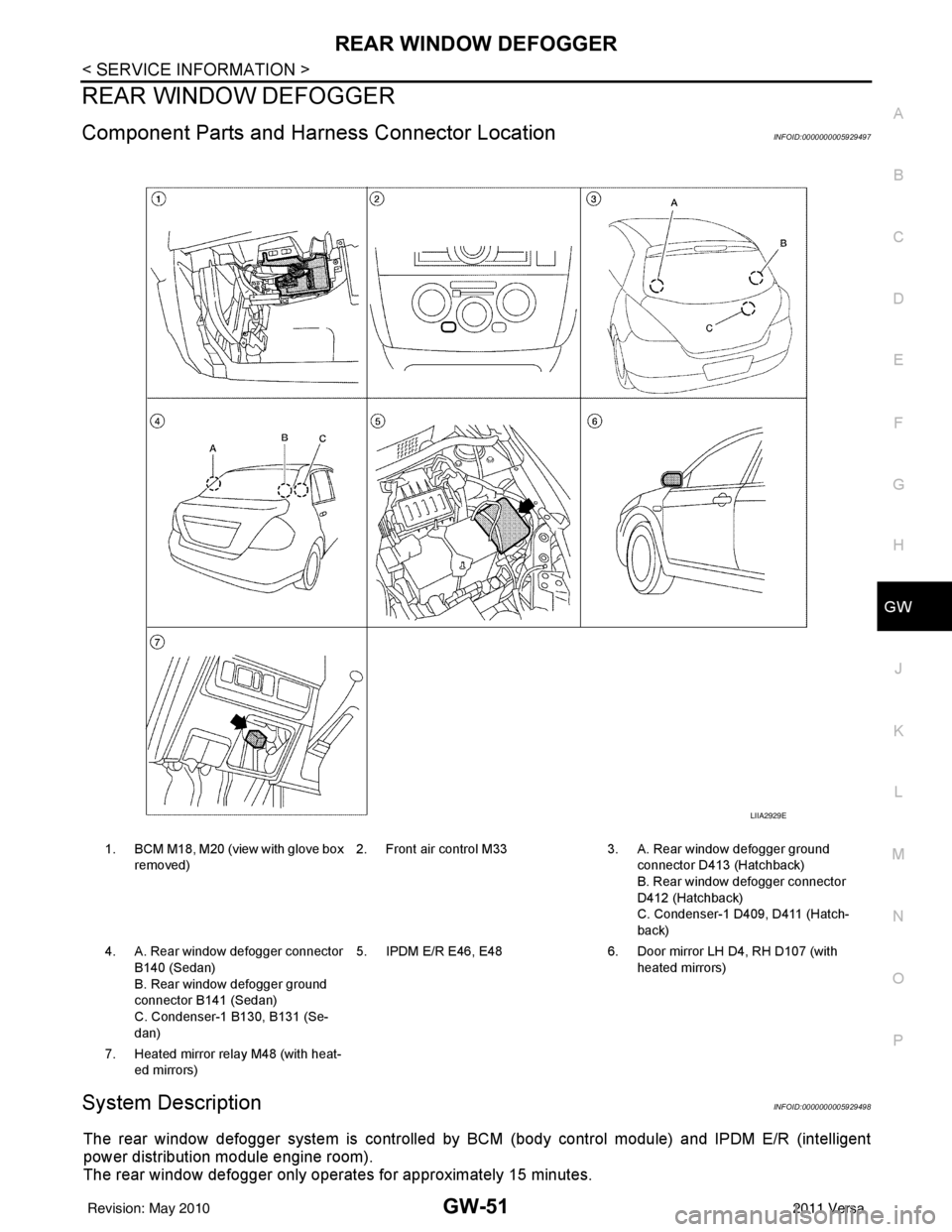
Component Parts and Har ness Connector LocationINFOID:0000000005929497
System DescriptionINFOID:0000000005929498
The rear window defogger system is controlled by BCM (body control module) and IPDM E/R (intelligent
power distribution module engine room).
The rear window defogger only operates for approximately 15 minutes.
1. BCM M18, M20 (view with glove box
removed) 2. Front air control M33 3. A. Rear window defogger ground
connector D413 (Hatchback)
B. Rear window defogger connector
D412 (Hatchback)
C. Condenser-1 D409, D411 (Hatch-
back)
4. A. Rear window defogger connector B140 (Sedan)
B. Rear window defogger ground
connector B141 (Sedan)
C. Condenser-1 B130, B131 (Se-
dan) 5. IPDM E/R E46, E48
6. Door mirror LH D4, RH D107 (with
heated mirrors)
7. Heated mirror relay M48 (with heat- ed mirrors)
LIIA2929E
Revision: May 2010 2011 Versa
Page 2806 of 3787

GW-52
< SERVICE INFORMATION >
REAR WINDOW DEFOGGER
Power is supplied at all times
• through 15A fuses (No. 46 and 47, located in the IPDM E/R)
• to rear window defogger relay
• through 10A fuse [No. 5 (with heated mirrors), located in the fuse block (J/B)]
• to heated mirror relay terminal 3
• through 40A fusible link (letter g , located in the fuse and fusible link box)
• to BCM terminal 70.
With the ignition switch turned to ON or START position, power is supplied
• through ignition relay
• to rear window defogger relay (located in the IPDM E/R)
• through 10A fuse [No. 6, located in the fuse block (J/B)]
• to BCM terminal 38.
Ground is supplied
• to BCM terminal 67 and
• to front air control terminal 8
• through body grounds M57 and M61
• to IPDM E/R terminals 39 and 59
• through body grounds E15 and E24.
When front air control (rear window defogger switch) is turned to ON, ground is supplied
• to BCM terminal 9
• through front air control terminal 3
• through front air control terminal 8
• through body grounds M57 and M61.
Then rear window defogger switch is illuminated.
Then BCM recognizes that rear window defogger switch is turned to ON.
Then it sends rear window defogger switch signals to IPDM E/R via CAN communication (CAN-H, CAN-L).
When IPDM E/R receives rear window defogger switch signals, ground is supplied
• to rear window defogger relay (located in the IPDM E/R)
• through IPDM E/R terminals 39 and 59
• through body grounds E15 and E24
Then rear window defogger relay is energized.
With power and ground supplied, rear window def ogger filaments heat and defog the rear window.
When rear window defogger relay is turned to ON (with heated mirrors), power is supplied
• through heated mirror relay terminal 5
• to door mirror (LH and RH) terminal 1.
Door mirror (LH and RH) is grounded through body grounds M57 and M61.
With power and ground supplied, rear window defogger filaments heat and defog the rear window and door
mirror filaments heat and defog the mirrors.
CAN Communication System DescriptionINFOID:0000000005929499
Refer to LAN-7, "System Description".
Revision: May 2010 2011 Versa
Page 2810 of 3787

GW-56
< SERVICE INFORMATION >
REAR WINDOW DEFOGGER
BCM Power Supply and Ground Circuit Inspection
INFOID:0000000005929506
Refer to BCS-16, "BCM Power Supply and Ground Circuit Inspection" .
Rear Window Defogger Swit ch Circuit InspectionINFOID:0000000005929507
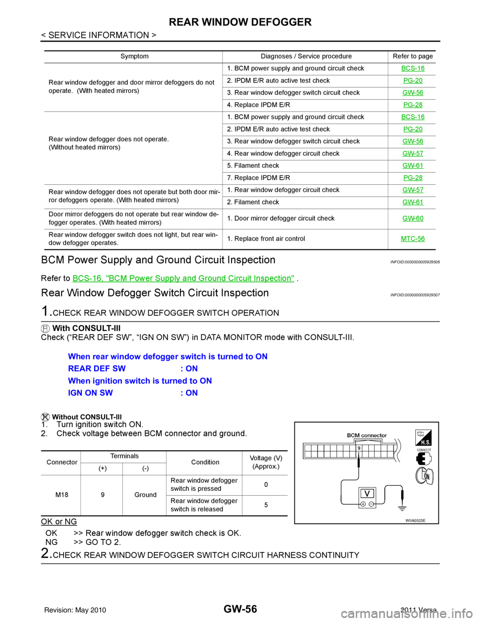
1.CHECK REAR WINDOW DEFOGGER SWITCH OPERATION
With CONSULT-III
Check (“REAR DEF SW”, “IGN ON SW”) in DATA MONITOR mode with CONSULT-III.
Without CONSULT-III
1. Turn ignition switch ON.
2. Check voltage between BCM connector and ground.
OK or NG
OK >> Rear window defogger switch check is OK.
NG >> GO TO 2.
2.CHECK REAR WINDOW DEFOGGER SWITCH CIRCUIT HARNESS CONTINUITY
Symptom Diagnoses / Service procedureRefer to page
Rear window defogger and door mirror defoggers do not
operate. (With heated mirrors) 1. BCM power supply and ground circuit check
BCS-16
2. IPDM E/R auto active test check PG-20
3. Rear window defogger switch circuit checkGW-56
4. Replace IPDM E/R PG-28
Rear window defogger does not operate.
(Without heated mirrors) 1. BCM power supply and ground circuit check
BCS-16
2. IPDM E/R auto active test check PG-20
3. Rear window defogger switch circuit checkGW-56
4. Rear window defogger circuit checkGW-57
5. Filament checkGW-61
7. Replace IPDM E/R PG-28
Rear window defogger does not operate but both door mir-
ror defoggers operate. (With heated mirrors) 1. Rear window defogger circuit check
GW-57
2. Filament checkGW-61
Door mirror defoggers do not operate but rear window de-
fogger operates. (With heated mirrors) 1. Door mirror defogger circuit check
GW-60
Rear window defogger switch does not light, but rear win-
dow defogger operates. 1. Replace front air control
MTC-56
When rear window defogger switch is turned to ON
REAR DEF SW: ON
When ignition switch is turned to ON
IGN ON SW : ON
ConnectorTe r m i n a l s
ConditionVoltage (V)
(Approx.)
(+) (-)
M18 9 Ground Rear window defogger
switch is pressed
0
Rear window defogger
switch is released 5
WIIA0523E
Revision: May 2010
2011 Versa
Page 2811 of 3787

REAR WINDOW DEFOGGERGW-57
< SERVICE INFORMATION >
C
DE
F
G H
J
K L
M A
B
GW
N
O P
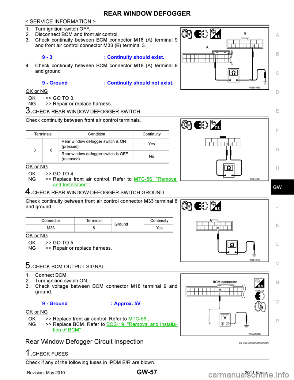
1. Turn ignition switch OFF.
2. Disconnect BCM and front air control.
3. Check continuity between BCM connector M18 (A) terminal 9 and front air control connector M33 (B) terminal 3.
4. Check continuity between BCM connector M18 (A) terminal 9 and ground
OK or NG
OK >> GO TO 3.
NG >> Repair or replace harness.
3.CHECK REAR WINDOW DEFOGGER SWITCH
Check continuity between fr ont air control terminals.
OK or NG
OK >> GO TO 4.
NG >> Replace front air control. Refer to MTC-56, "
Removal
and Installation" .
4.CHECK REAR WINDOW DEFOGGER SWITCH GROUND
Check continuity between front air control connector M33 terminal 8
and ground.
OK or NG
OK >> GO TO 5.
NG >> Repair or replace harness.
5.CHECK BCM OUTPUT SIGNAL
1. Connect BCM.
2. Turn ignition switch ON.
3. Check voltage between BCM connector M18 terminal 9 and ground.
OK or NG
OK >> Replace front air control. Refer to MTC-56 .
NG >> Replace BCM. Refer to BCS-19, "
Removal and Installa-
tion of BCM" .
Rear Window Defogger Circuit InspectionINFOID:0000000005929508
1.CHECK FUSES
Check if any of the following fuses in IPDM E/R are blown. 9 - 3
: Continuity should exist.
9 - Ground : Continuity should not exist.
PIIB6479E
Terminals Condition Continuity
38 Rear window defogger switch is ON
(pressed)
Ye s
Rear window defogger switch is OFF
(released) No
PIIB6480E
Connector
Terminal
Ground Continuity
8Y es
M33
PIIB6481E
9 - Ground : Approx. 5V
WIIA0523E
Revision: May 2010 2011 Versa
Page 2833 of 3787

IP-12
< ON-VEHICLE REPAIR >
INSTRUMENT PANEL ASSEMBLY
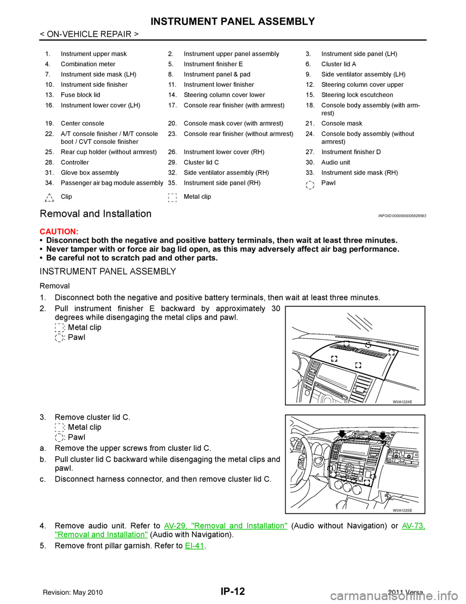
Removal and Installation
INFOID:0000000005929593
CAUTION:
• Disconnect both the negative and positive battery terminals, then wait at least three minutes.
• Never tamper with or force air bag lid open, as this may adversely affect air bag performance.
• Be careful not to scratch pad and other parts.
INSTRUMENT PANEL ASSEMBLY
Removal
1. Disconnect both the negative and positive battery terminals, then wait at least three minutes.
2. Pull instrument finisher E backward by approximately 30
degrees while disengaging the metal clips and pawl.
: Metal clip
: Pawl
3. Remove cluster lid C. : Metal clip
: Pawl
a. Remove the upper screws from cluster lid C.
b. Pull cluster lid C backward while disengaging the metal clips and pawl.
c. Disconnect harness connector, and then remove cluster lid C.
4. Remove audio unit. Refer to AV-29, "
Removal and Installation" (Audio without Navigation) or AV-73,
"Removal and Installation" (Audio with Navigation).
5. Remove front pillar garnish. Refer to EI-41
.
1. Instrument upper mask 2. Instrument upper panel assembly 3. Instrument side panel (LH)
4. Combination meter 5. Instrument finisher E 6. Cluster lid A
7. Instrument side mask (LH) 8. Instrument panel & pad 9. Side ventilator assembly (LH)
10. Instrument side finisher 11. Instrument lower finisher 12. Steering column cover upper
13. Fuse block lid 14. Steering column cover lower 15. Steering lock escutcheon
16. Instrument lower cover (LH) 17. Console rear finisher (with armrest) 18. Console body assembly (with arm- rest)
19. Center console 20. Console mask cover (with armrest) 21. Console mask
22. A/T console finisher / M/T console boot / CVT console finisher 23. Console rear finisher (without armrest) 24. Console body assembly (without
armrest)
25. Rear cup holder (without armrest) 26. Instrument lower cover (RH) 27. Instrument finisher D
28. Controller 29. Cluster lid C 30. Audio unit
31. Glove box assembly 32. Side ventilator assembly (RH) 33. Instrument side mask (RH)
34. Passenger air bag module assembly 35. Instrument side panel (RH) Pawl
Clip Metal clip
WIIA1224E
WIIA1225E
Revision: May 2010 2011 Versa
Page 2874 of 3787
![NISSAN TIIDA 2011 Service Repair Manual LAN-28
< SERVICE INFORMATION >[CAN]
CAN COMMUNICATION SYSTEM
*1: A/T models
*2: CVT models
*3: Models with VDC
*4: Models for Canada
*5: Models for USA
*6: Models without ABS
NOTE:
CAN data of the air NISSAN TIIDA 2011 Service Repair Manual LAN-28
< SERVICE INFORMATION >[CAN]
CAN COMMUNICATION SYSTEM
*1: A/T models
*2: CVT models
*3: Models with VDC
*4: Models for Canada
*5: Models for USA
*6: Models without ABS
NOTE:
CAN data of the air](/manual-img/5/57396/w960_57396-2873.png)
LAN-28
< SERVICE INFORMATION >[CAN]
CAN COMMUNICATION SYSTEM
*1: A/T models
*2: CVT models
*3: Models with VDC
*4: Models for Canada
*5: Models for USA
*6: Models without ABS
NOTE:
CAN data of the air bag diagnosis sensor unit is not used by usual service work, thus it is omitted.
KEY warning lamp signal
T R
LOCK warning lamp signal T R
Panic alarm request signal RT
Fuel level sensor signal RT
Overdrive control switch signal TR R
Parking brake switch signal
*3TR
Stop lamp switch signal T R R
Vehicle speed signal RRRR T
RRR T R
R
*6T*6
Steering angle sensor signal*3TR
ABS warning lamp signal RT
Brake warning lamp signal RT
SLIP indicator lamp signal
*3RT
VDC OFF indicator lamp signal
*3RT
VDC warning lamp signal
*3RT
A/T check indicator signal RT
A/T self-diagnosis signal R T
Input speed signal R T
OD OFF indicator signal RT
Output shaft revolution signal R T T
Shift position indicator signal R
R
*3TT
CVT self-diagnosis signal R T
Input shaft revolution signal R T
OD OFF indicator signal RT
Front wiper stop position signal R T
High beam status signal R T
Low beam status signal R T
Oil pressure switch signal R RR T
Rear window defogger control signal R T
Signal name/Connecting unit
ECM
BCM
EPS
I-KEY M&A
STRG ABS
TCM
*1
TCM
*2
IPDM-E
Revision: May 2010 2011 Versa
Page 3155 of 3787
![NISSAN TIIDA 2011 Service Repair Manual ENGINE OILLU-7
< ON-VEHICLE MAINTENANCE > [HR16DE]
C
D
E
F
G H
I
J
K L
M A
LU
NP
O
ON-VEHICLE MAINTENANCE
ENGINE OIL
InspectionINFOID:0000000005928687
ENGINE OIL LEVEL
NOTE:
Park vehicle on a level su NISSAN TIIDA 2011 Service Repair Manual ENGINE OILLU-7
< ON-VEHICLE MAINTENANCE > [HR16DE]
C
D
E
F
G H
I
J
K L
M A
LU
NP
O
ON-VEHICLE MAINTENANCE
ENGINE OIL
InspectionINFOID:0000000005928687
ENGINE OIL LEVEL
NOTE:
Park vehicle on a level su](/manual-img/5/57396/w960_57396-3154.png)
ENGINE OILLU-7
< ON-VEHICLE MAINTENANCE > [HR16DE]
C
D
E
F
G H
I
J
K L
M A
LU
NP
O
ON-VEHICLE MAINTENANCE
ENGINE OIL
InspectionINFOID:0000000005928687
ENGINE OIL LEVEL
NOTE:
Park vehicle on a level surface, wait 10 minutes and check the engine oil level.
1. Pull out oil level gauge and wipe it clean.
2. Insert oil level gauge and make sure the engine oil level is within
the range (A) as shown.
3. If it is out of range, adjust it.
ENGINE OIL APPEARANCE
• Check engine oil for white milky appearance or excessive contamination.
• If engine oil becomes white, it is highly probable t hat it is contaminated with engine coolant. Repair or
replace damaged parts.
ENGINE OIL LEAKAGE
Check for engine oil leakage around the following areas:
• Oil pan (upper and lower)
• Oil pan drain plug
• Oil pressure switch
• Oil filter
• Intake valve timing control solenoid valve
• Front cover
• Mating surface between cylinder head and camshaft bracket
• Mating surface between cylinder block and cylinder head
• Mating surface between cylinder head and rocker cover
• Crankshaft oil seals (front and rear)
• Oil filter (for intake valve timing control)
OIL PRESSURE CHECK
WARNING:
• Be careful not to burn yoursel f, as engine oil may be hot.
• For engine oil pressure check the transaxle should be in “Park position” (A/T models) or “Neutral
position” (M/T models), and apply the parking brake securely.
1. Check engine oil level.
2. Remove engine under cover. Refer to EI-15, "
Removal and Installation".
3. Disconnect harness connector at oil pressure switch (2), and remove oil pressure switch (2) from the cylinder block (1) using
suitable tool.
CAUTION:
Never drop or shock oil pressure switch.
JPBIA0554ZZ
PBIC3817E
Revision: May 2010 2011 Versa