Page 3472 of 3787

PG-52
< SERVICE INFORMATION >
HARNESS
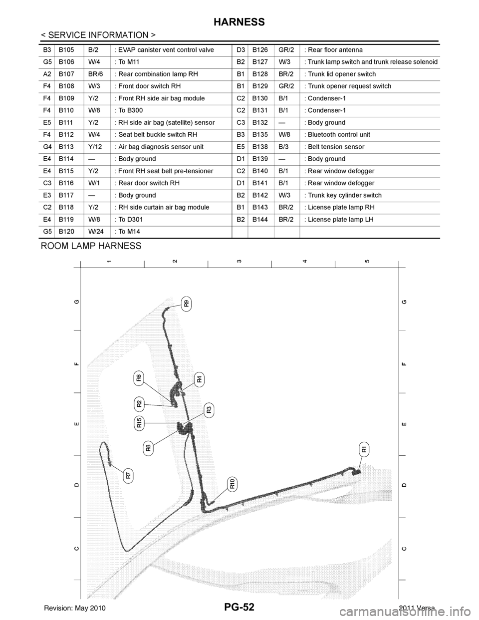
ROOM LAMP HARNESS
B3 B105 B/2 : EVAP canister vent control valve D3 B126 GR/2 : Rear floor antenna
G5 B106 W/4 : To M11B2 B127 W/3 : Trunk lamp switch and trunk release solenoid
A2 B107 BR/6 : Rear combination lamp RH B1 B128 BR/2 : Trunk lid opener switch
F4 B108 W/3 : Front door switch RH B1 B129 GR/2 : Trunk opener request switch
F4 B109 Y/2 : Front RH side air bag module C2 B130 B/1 : Condenser-1
F4 B110 W/8 : To B300 C2 B131 B/1 : Condenser-1
E5 B111 Y/2 : RH side air bag (satellite) sensor C3 B132 — : Body ground
F4 B112 W/4 : Seat belt buckle switch RH B3 B135 W/8 : Bluetooth control unit
G4 B113 Y/12 : Air bag diagnosis sensor unit E5 B138 B/3 : Belt tension sensor
E4 B114 — : Body ground D1 B139 — : Body ground
E4 B115 Y/2 : Front RH seat belt pre-tensioner C2 B140 B/1 : Rear window defogger
C3 B116 W/1 : Rear door switch RH D1 B141 B/1 : Rear window defogger
E3 B117 — : Body ground B2 B142 W/3 : Trunk key cylinder switch
C2 B118 Y/2 : RH side curtain air bag module B1 B143 BR/2 : License plate lamp RH
E4 B119 W/8 : To D301 B2 B144 BR/2 : License plate lamp LH
G5 B120 W/24 : To M14
Revision: May 2010 2011 Versa
Page 3478 of 3787

PG-58
< SERVICE INFORMATION >
HARNESS
Wiring Diagram Codes (Cell Codes)
INFOID:0000000005928356
Use the chart below to find out what each wiring diagram code stands for.
Refer to the wiring diagram code in the alphabetical index to find the location (page number) of each wiring
diagram.
D4 D406 W/2 : Back door request switch C2 D413 B/1 : Rear window defogger (-)
E2 D407 W/2 : High mounted stop lamp
Code Section Wiring Diagram Name
ABS BRC Anti-lock Brake System
A/C,M MTC Manual Air Conditioner
APPS1 EC Accelerator Pedal Position Sensor
A/F EC Air Fuel Ratio Sensor 1
A/FH EC Air Fuel Ratio Sensor 1 Heater
APPS2 EC Accelerator Pedal Position Sensor
APPS3 EC Accelerator Pedal Position Sensor
ASC/BS EC ASCD Brake Switch
ASC/SW EC ASCD Steering Switch
ASCBOF EC ASCD Brake Switch
ASCIND EC ASCD Indicator
AT/IND DI A/T Indicator Lamp
AUDIO AV Audio
BACK/L LT Back-up Lamp
BA/FTS AT A/T Fluid Temperature Sensor and TCM Power Supply
B/DOOR BL Back Door Opener
BRK/SW EC Brake Switch
CAN AT CAN Communication Line
CAN CVT CAN Communication Line
CAN EC CAN Communication Line
CAN LAN CAN System
CHARGE SC Charging System
CHIME DI Warning Chime
COOL/F EC Cooling Fan Control
COMBSW LT Combination Switch
COMM AV Audio Visual Communication System
CVTIND DI CVT Indicator Lamp
D/LOCK BL Power Door Lock
DEF GW Rear Window Defogger
DTRL LT Headlamp - With Daytime Light System
ECTS EC Engine Coolant Temperature Sensor
ENGSS AT Engine Speed Signal
EPS STC Electronic Controlled Power Steering
ETC1 EC Electric Throttle Control Function
ETC2 EC Throttle Control Motor Relay
ETC3 EC Throttle Control Motor
F/FOG LT Front Fog Lamp
F/PUMP EC Fuel Pump
FTS AT A/T Fluid Temperature Sensor
FTS CVT CVT Fluid Temperature Sensor Circuit
FTTS EC Fuel Tank Temperature Sensor
FUEL EC Fuel Ignition System Function
HEATER MTC Heater System
Revision: May 2010 2011 Versa
Page 3556 of 3787

PRECAUTIONSRSU-3
< SERVICE INFORMATION >
C
DF
G H
I
J
K L
M A
B
RSU
N
O P
5. When the repair work is completed, return the ignition switch to the ″LOCK ″ position before connecting
the battery cables. (At this time, the steering lock mechanism will engage.)
6. Perform a self-diagnosis check of al l control units using CONSULT-III.
Precaution for Rear SuspensionINFOID:0000000005931081
• When installing the rubber bushings, the final tightening must be done under unladen condition and with the
tires on level ground. Oil will shorten the life of the rubber bushings, so wipe off any spilled oil immediately.
• Unladen condition means the fuel tank, engine coolant and lubricants are at the full specification. The spare
tire, jack, hand tools, and mats are in their designated positions.
• After installing suspension components, check the wheel alignment.
• Caulking nuts are not reusable. Always use new caulking nuts for installation. New caulking nuts are pre- oiled, do not apply any additional lubrication.
Revision: May 2010 2011 Versa
Page 3734 of 3787

WT-16
< SERVICE INFORMATION >
TROUBLE DIAGNOSES
Preliminary Check
INFOID:0000000005931109
BASIC INSPECTION
1.CHECK ALL TIRE PRESSURES
Check all tire pressures. Refer to WT-28, "
Tire" .
OK or NG
OK >> GO TO 2.
NG >> Adjust tire pressure to specified value.
2.CHECK LOW TIRE PRESSURE WARNING LAMP ACTIVATION
Check low tire pressure warning lamp activation.
Does warning lamp activate for 1 second when ignition switch is turned ON?
YES >> GO TO 3.
NO >> GO TO WT-23, "
Low Tire Pressure Warning Lamp Does Not Come On When Ignition Switch Is
Turned On" .
3.CHECK BCM CONNECTOR
1. Disconnect BCM harness connector.
2. Check terminals for damage or loose connection.
3. Reconnect harness connector.
OK or NG
OK >> GO TO 4.
NG >> Repair or replace damaged parts.
4.CHECK TRANSMITTER ACTIVATION TOOL
Check transmitter activation tool battery.
OK or NG
OK >> Carry out self-diagnosis.
NG >> Replace battery in transmitter activation tool.
Self-Diagnosis (With CONSULT-III)INFOID:0000000005931110
DESCRIPTION
During driving, the tire pressure monitoring system receives the signal trans mitted from the transmitter
installed in each wheel, and turns on the low tire pressure warning lamp when the tire pressure becomes low.
The control unit (BCM) for this system has pressure judgement and self-diagnosis functions.
FUNCTION
When the tire pressure monitoring system detects low inflation pressure or an internal malfunction, the low tire
pressure warning lamp in the combination meter comes on. The malfunction location is indicated by the low
tire pressure warning lamp flashing and the buzzer sounding.
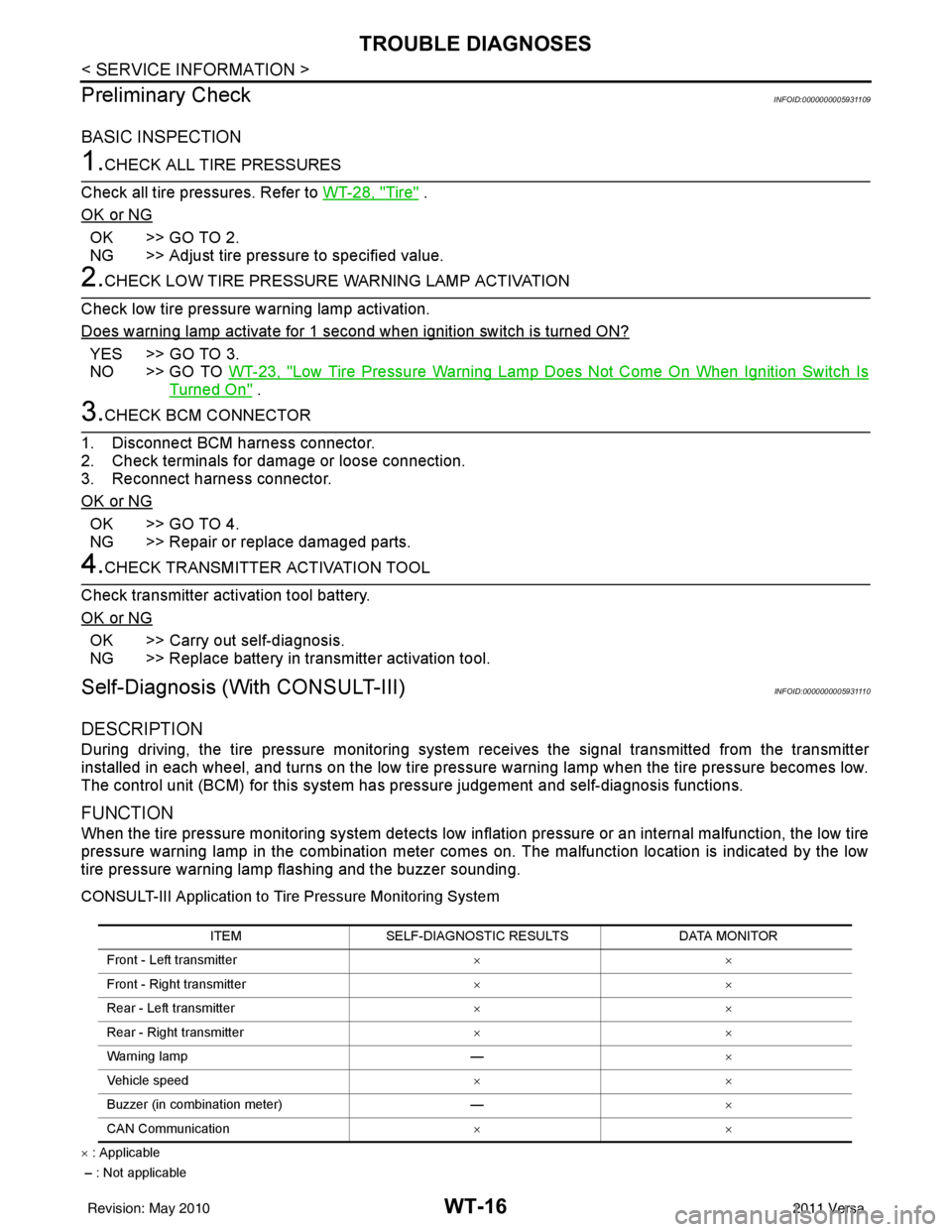
CONSULT-III Application to Tire Pressure Monitoring System
× : Applicable
– : Not applicable ITEM
SELF-DIAGNOSTIC RESULTS DATA MONITOR
Front - Left transmitter ××
Front - Right transmitter ××
Rear - Left transmitter ××
Rear - Right transmitter ××
Warning lamp —×
Vehicle speed ××
Buzzer (in combination meter) —×
CAN Communication ××
Revision: May 2010 2011 Versa