Page 857 of 3787
BR-10
< SERVICE INFORMATION >
BRAKE FLUID
3. With brake pedal depressed, loosen bleed valve to let the air out, and then tighten it immediately.
4. Repeat steps 2, 3 until no more air comes out.
5. Tighten bleed valve to specified torque. Refer to BR-25, "
Component" (front disc brake), BR-35, "Compo-
nent" (rear drum brake).
6. Following the steps 1 to 5 above, with master cylinder reservoir tank filled at least half way, bleed air from
the rear right, front left, rear left, and front right brake, in that order.
Revision: May 2010 2011 Versa
Page 858 of 3787
BRAKE TUBE AND HOSEBR-11
< SERVICE INFORMATION >
C
DE
G H
I
J
K L
M A
B
BR
N
O P
BRAKE TUBE AND HOSE
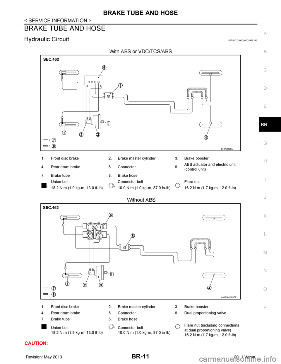
Hydraulic CircuitINFOID:0000000005928396
With ABS or VDC/TCS/ABS
Without ABS
CAUTION:
SFIA3068E
1. Front disc brake 2. Brake master cylinder3. Brake booster
4. Rear drum brake 5. Connector6.ABS actuator and electric unit
(control unit)
7. Brake tube 8. Brake hose
: Union bolt
:Connector bolt
:Flare nut
18.2 N.m (1.9 kg-m, 13.0 ft-lb) 10.0 N.m (1.0 kg-m, 87.0 in-lb) 16.2 N.m (1.7 kg-m, 12.0 ft-lb)
AWFIA0525ZZ
1. Front disc brake 2. Brake master cylinder3. Brake booster
4. Rear drum brake 5. Connector6. Dual proportioning valve
7. Brake tube 8. Brake hose
: Union bolt
18.2 N.m (1.9 kg-m, 13.0 ft-lb) :
Connector bolt
10.0 N.m (1.0 kg-m, 87.0 in-lb) :
Flare nut (including connections
at dual proportioning valve)
16.2 N.m (1.7 kg-m, 12.0 ft-lb)
Revision: May 2010
2011 Versa
Page 882 of 3787
REAR DRUM BRAKEBR-35
< SERVICE INFORMATION >
C
DE
G H
I
J
K L
M A
B
BR
N
O P
REAR DRUM BRAKE
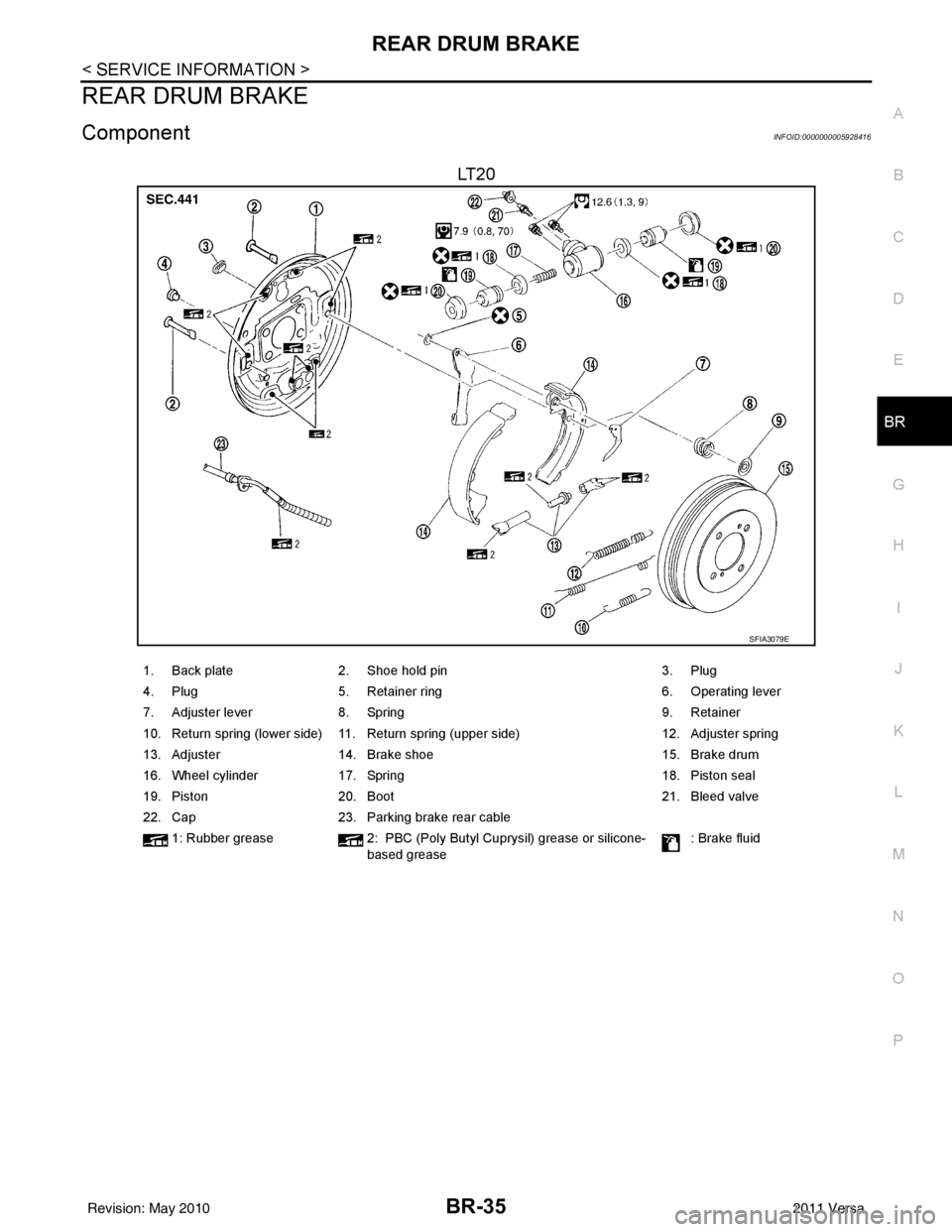
ComponentINFOID:0000000005928416
LT 2 0
SFIA3079E
1. Back plate 2. Shoe hold pin 3. Plug
4. Plug 5. Retainer ring 6. Operating lever
7. Adjuster lever 8. Spring 9. Retainer
10. Return spring (lower side) 11. Return spring (upper side) 12. Adjuster spring
13. Adjuster 14. Brake shoe 15. Brake drum
16. Wheel cylinder 17. Spring 18. Piston seal
19. Piston 20. Boot 21. Bleed valve
22. Cap 23. Parking brake rear cable
1: Rubber grease 2: PBC (Poly Butyl Cuprysil) grease or silicone-
based grease : Brake fluid
Revision: May 2010
2011 Versa
Page 883 of 3787
BR-36
< SERVICE INFORMATION >
REAR DRUM BRAKE
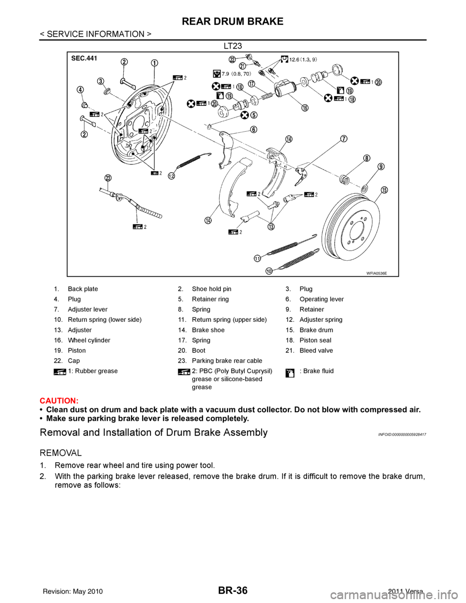
LT23
CAUTION:
• Clean dust on drum and back plate with a vacuum dust collector. Do not blow with compressed air.
• Make sure parking brake lever is released completely.
Removal and Installation of Drum Brake AssemblyINFOID:0000000005928417
REMOVAL
1. Remove rear wheel and tire using power tool.
2. With the parking brake lever released, remove the brak e drum. If it is difficult to remove the brake drum,
remove as follows:
WFIA0536E
1. Back plate 2. Shoe hold pin3. Plug
4. Plug 5. Retainer ring6. Operating lever
7. Adjuster lever 8. Spring9. Retainer
10. Return spring (lower side) 11. Return spring (upper side) 12. Adjuster spring
13. Adjuster 14. Brake shoe15. Brake drum
16. Wheel cylinder 17. Spring18. Piston seal
19. Piston 20. Boot21. Bleed valve
22. Cap 23. Parking brake rear cable
1: Rubber grease 2: PBC (Poly Butyl Cuprysil)
grease or silicone-based
grease : Brake fluid
Revision: May 2010
2011 Versa
Page 884 of 3787
REAR DRUM BRAKEBR-37
< SERVICE INFORMATION >
C
DE
G H
I
J
K L
M A
B
BR
N
O P
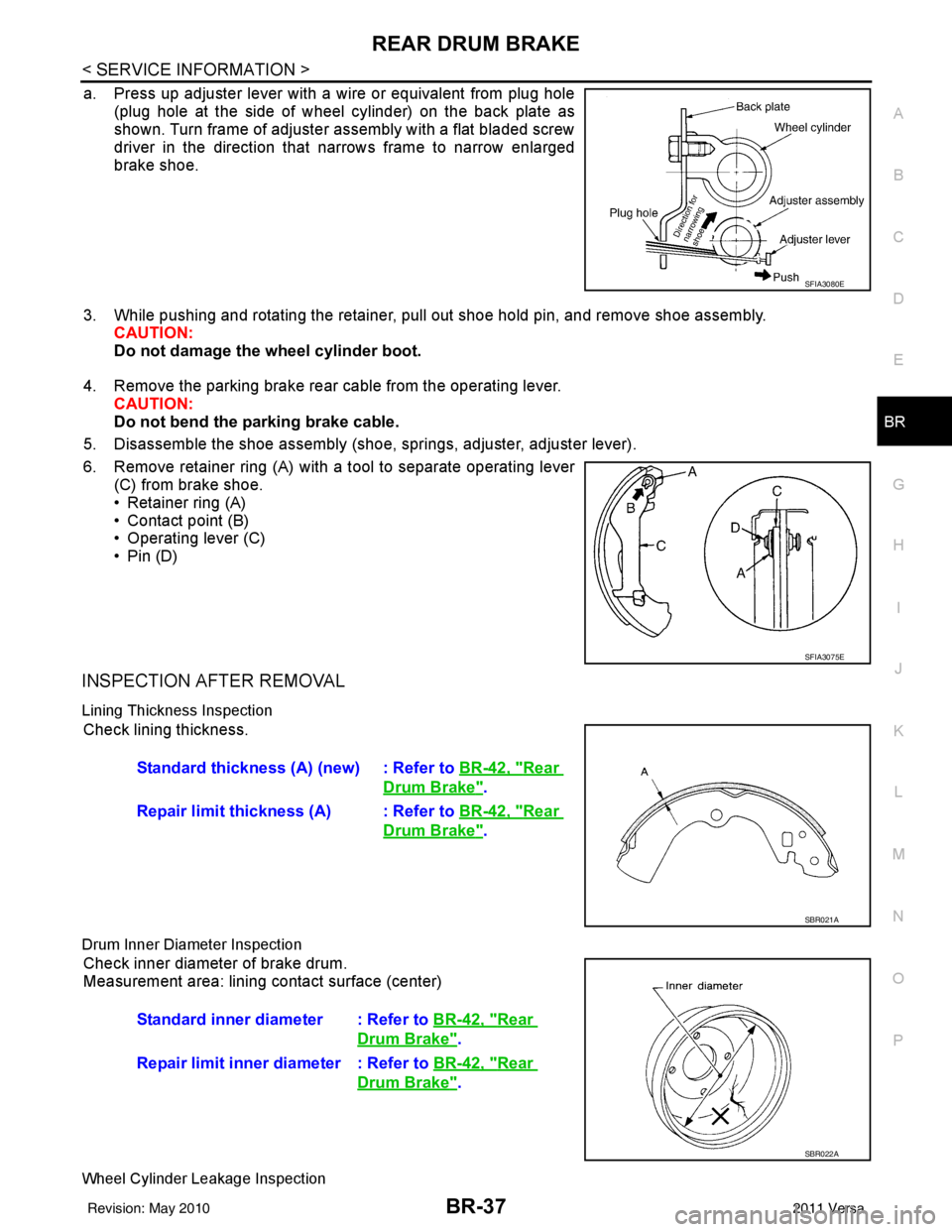
a. Press up adjuster lever with a wire or equivalent from plug hole (plug hole at the side of wheel cylinder) on the back plate as
shown. Turn frame of adjuster assembly with a flat bladed screw
driver in the direction that narrows frame to narrow enlarged
brake shoe.
3. While pushing and rotating the retainer, pull out shoe hold pin, and remove shoe assembly. CAUTION:
Do not damage the wheel cylinder boot.
4. Remove the parking brake rear cable from the operating lever. CAUTION:
Do not bend the parking brake cable.
5. Disassemble the shoe assembly (shoe, springs, adjuster, adjuster lever).
6. Remove retainer ring (A) with a tool to separate operating lever (C) from brake shoe.
• Retainer ring (A)
• Contact point (B)
• Operating lever (C)
•Pin (D)
INSPECTION AFTER REMOVAL
Lining Thickness Inspection
Check lining thickness.
Drum Inner Diameter Inspection
Check inner diameter of brake drum.
Measurement area: lining contact surface (center)
Wheel Cylinder Leakage Inspection
SFIA3080E
SFIA3075E
Standard thickness (A) (new) : Refer to BR-42, "Rear
Drum Brake".
Repair limit thickness (A) : Refer to BR-42, "
Rear
Drum Brake".
SBR021A
Standard inner diameter : Refer to BR-42, "Rear
Drum Brake".
Repair limit inner diameter : Refer to BR-42, "
Rear
Drum Brake".
SBR022A
Revision: May 2010 2011 Versa
Page 885 of 3787
BR-38
< SERVICE INFORMATION >
REAR DRUM BRAKE
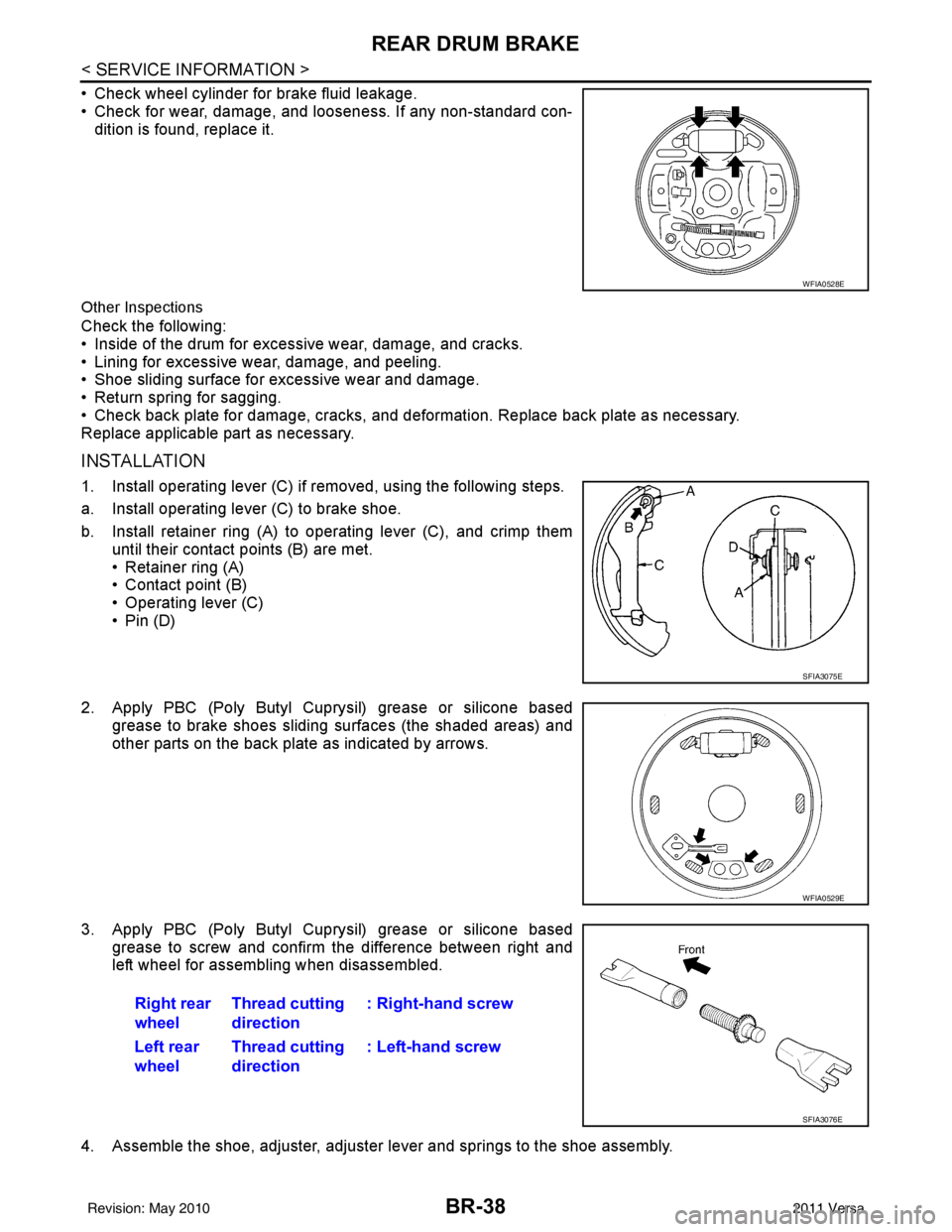
• Check wheel cylinder for brake fluid leakage.
• Check for wear, damage, and looseness. If any non-standard con-dition is found, replace it.
Other Inspections
Check the following:
• Inside of the drum for excessive wear, damage, and cracks.
• Lining for excessive wear, damage, and peeling.
• Shoe sliding surface for excessive wear and damage.
• Return spring for sagging.
• Check back plate for damage, cracks, and deformation. Replace back plate as necessary.
Replace applicable part as necessary.
INSTALLATION
1. Install operating lever (C) if removed, using the following steps.
a. Install operating lever (C) to brake shoe.
b. Install retainer ring (A) to operating lever (C), and crimp them
until their contact points (B) are met.
• Retainer ring (A)
• Contact point (B)
• Operating lever (C)
•Pin (D)
2. Apply PBC (Poly Butyl Cuprysil) grease or silicone based grease to brake shoes sliding surfaces (the shaded areas) and
other parts on the back plate as indicated by arrows.
3. Apply PBC (Poly Butyl Cuprysil) grease or silicone based grease to screw and confirm the difference between right and
left wheel for assembling when disassembled.
4. Assemble the shoe, adjuster, adjuster lever and springs to the shoe assembly.
WFIA0528E
SFIA3075E
WFIA0529E
Right rear
wheel Thread cutting
direction : Right-hand screw
Left rear
wheel Thread cutting
direction : Left-hand screw
SFIA3076E
Revision: May 2010
2011 Versa
Page 886 of 3787
REAR DRUM BRAKEBR-39
< SERVICE INFORMATION >
C
DE
G H
I
J
K L
M A
B
BR
N
O P
5. Connect the parking brake rear cable to the operating lever.
6. Install the shoe assembly. After assembly, be sure that each part is installed properly. CAUTION:
Do not damage the wheel cylinder piston boot.
7. Install the brake drum.
8. Depress brake pedal for several times (approximately 2 or 3 times).
9. Adjust clearance of brake shoe. Refer to PB-5, "
On-Vehicle Service".
10. Install rear wheel and tire. Refer to WT-7, "
Adjustment".
Removal and Installati on of Wheel CylinderINFOID:0000000005928418
REMOVAL
1. Drain the brake fluid. Refer to BR-9, "Drain and Refill".
2. Remove the rear brake shoe assembly. Refer to BR-36, "
Removal and Installation of Drum Brake Assem-
bly".
3. Remove the bleed valve.
4. Disconnect the brake tube from the wheel cylinder.
5. Remove the wheel cylinder bolts and then remove the wheel cylinder from the back plate.
INSTALLATION
Installation is in the reverse order of removal.
• Tighten bolts and bleed valve to the specified torque. Refer to BR-35, "
Component".
• Refill with new brake fluid and bleed the air. Refer to BR-9, "
Bleeding Brake System".
Disassembly and Assembly of Wheel CylinderINFOID:0000000005928419
DISASSEMBLY
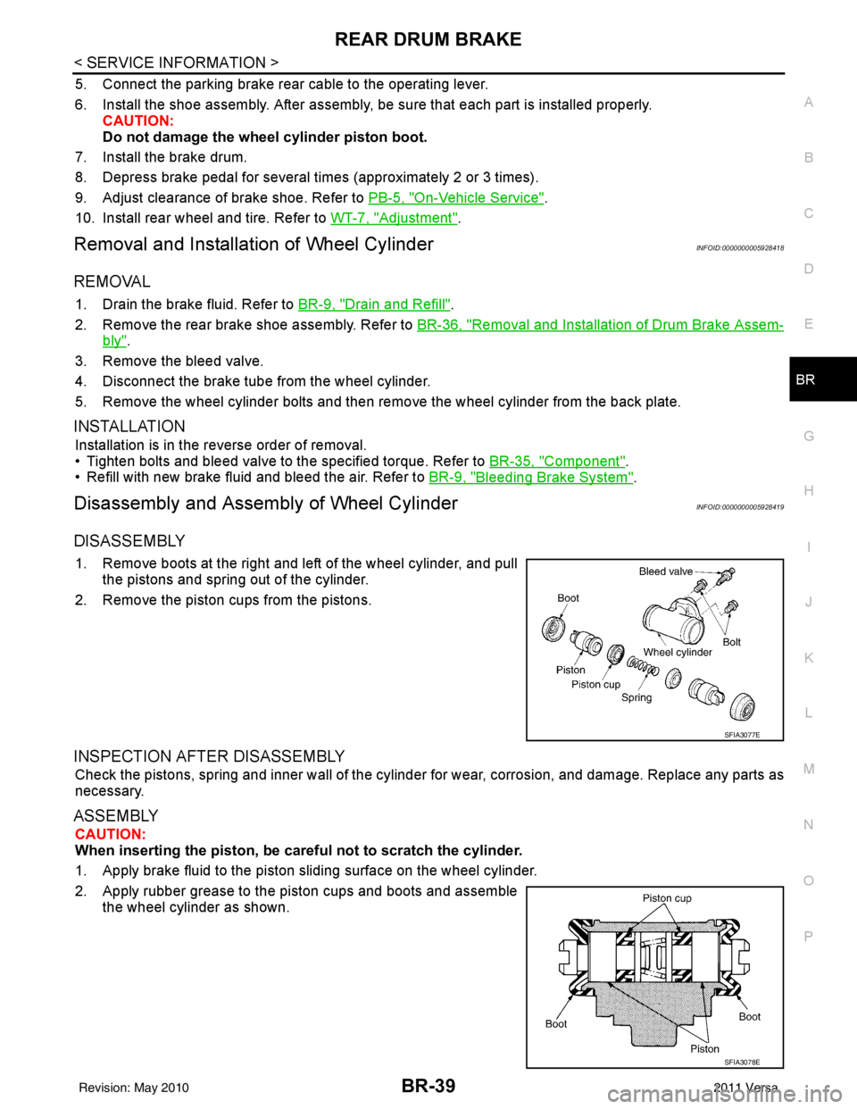
1. Remove boots at the right and left of the wheel cylinder, and pull
the pistons and spring out of the cylinder.
2. Remove the piston cups from the pistons.
INSPECTION AFTER DISASSEMBLY
Check the pistons, spring and inner wall of the cylinder for wear, corrosion, and damage. Replace any parts as
necessary.
ASSEMBLY
CAUTION:
When inserting the piston, be caref ul not to scratch the cylinder.
1. Apply brake fluid to the piston sliding surface on the wheel cylinder.
2. Apply rubber grease to the piston cups and boots and assemble the wheel cylinder as shown.
SFIA3077E
SFIA3078E
Revision: May 2010 2011 Versa
Page 887 of 3787

BR-40
< SERVICE INFORMATION >
SERVICE DATA AND SPECIFICATIONS (SDS)
SERVICE DATA AND SPECIFICATIONS (SDS)
General SpecificationINFOID:0000000005928420
HR16DE
MR18DE
TypeWith ABS or VDC/TCS/ABSWithout ABS
Front brake Brake model AD22VK
Cylinder bore diameter 53.97 mm (2.125 in)
Pad
Length × width × thickness 115.0 mm ×
41.0 mm × 9.0 mm
(4.528 in × 1.614 in × 0.354 in)
Rotor outer diameter × thickness 260 mm × 22.0 mm (10.24 in × 0.866 in)
Rear brake Brake model LT20
Cylinder bore diameter 15.87 mm (0.625 in)17.46 mm (0.687 in)
Drum inner diameter 203 mm (7.992 in)
Master cylinder Cylinder bore diameter 22.22 mm (0.875 in)
Brake booster Booster model C255
Diaphragm diameter 255 mm (10.04 in)
Recommended brake fluid DOT 3
Front brake Brake modelCLZ25VF
Cylinder bore diameter 57.2 mm (2.252 in)
Pad
Length × width × thickness 125.6 mm
× 48.0 mm × 9.5 mm
(4.945 in × 1.890 in × 0.374 in)
Rotor outer diameter × thickness 280 mm × 24.0 mm (11.02 in × 0.945 in)
Rear brake Brake model LT23
Cylinder bore diameter 19.06 mm (0.750 in)
Drum inner diameter 228.6 mm (9.000 in)
Master cylinder Cylinder bore diameter 23.81 ± 0.015 mm (0.937 ± 0.001 in)
Brake booster Booster model C255
Diaphragm diameter 255 mm (10.04 in)
Recommended brake fluid DOT 3
Revision: May 2010 2011 Versa