2011 NISSAN TIIDA Rear drum brake
[x] Cancel search: Rear drum brakePage 889 of 3787
BR-42
< SERVICE INFORMATION >
SERVICE DATA AND SPECIFICATIONS (SDS)
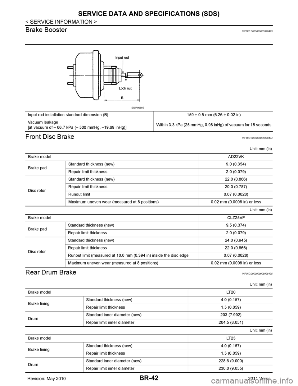
Brake Booster
INFOID:0000000005928423
Front Disc BrakeINFOID:0000000005928424
Unit: mm (in)
Unit: mm (in)
Rear Drum BrakeINFOID:0000000005928425
Unit: mm (in)
Unit: mm (in)
Input rod installation standard dimension (B) 159 ± 0.5 mm (6.26 ± 0.02 in)
Vacuum leakage
[at vacuum of – 66.7 kPa (– 500 mmHg, –19.69 inHg)] Within 3.3 kPa (25 mmHg, 0.98 inHg) of vacuum for 15 seconds
SGIA0060E
Brake model
AD22VK
Brake pad Standard thickness (new)
9.0 (0.354)
Repair limit thickness 2.0 (0.079)
Disc rotor Standard thickness (new)
22.0 (0.866)
Repair limit thickness 20.0 (0.787)
Runout limit 0.07 (0.0028)
Maximum uneven wear (measured at 8 positions) 0.02 mm (0.0008 in) or less
Brake model CLZ25VF
Brake pad Standard thickness (new)
9.5 (0.374)
Repair limit thickness 2.0 (0.079)
Disc rotor Standard thickness (new)
24.0 (0.945)
Repair limit thickness 22.0 (0.866)
Runout limit (measured at 10.0 mm (0.394 in) inside the disc edge 0.07 (0.0028)
Maximum uneven wear (measured at 8 positions) 0.02 mm (0.0008 in) or less
Brake model LT 2 0
Brake lining Standard thickness
(new) 4.0 (0.157)
Repair limit thickness 1.5 (0.059)
Drum Standard inner diameter (new)
203 (7.992)
Repair limit inner diameter 204.5 (8.051)
Brake model LT 2 3
Brake lining Standard thickness (new)
4.0 (0.157)
Repair limit thickness 1.5 (0.059)
Drum Standard inner diameter (new)
228.6 (9.000)
Repair limit inner diameter 230.0 (9.055)
Revision: May 2010 2011 Versa
Page 3218 of 3787
CHASSIS AND BODY MAINTENANCEMA-47
< SERVICE INFORMATION >
C
DE
F
G H
I
J
K
M A
B
MA
N
O P
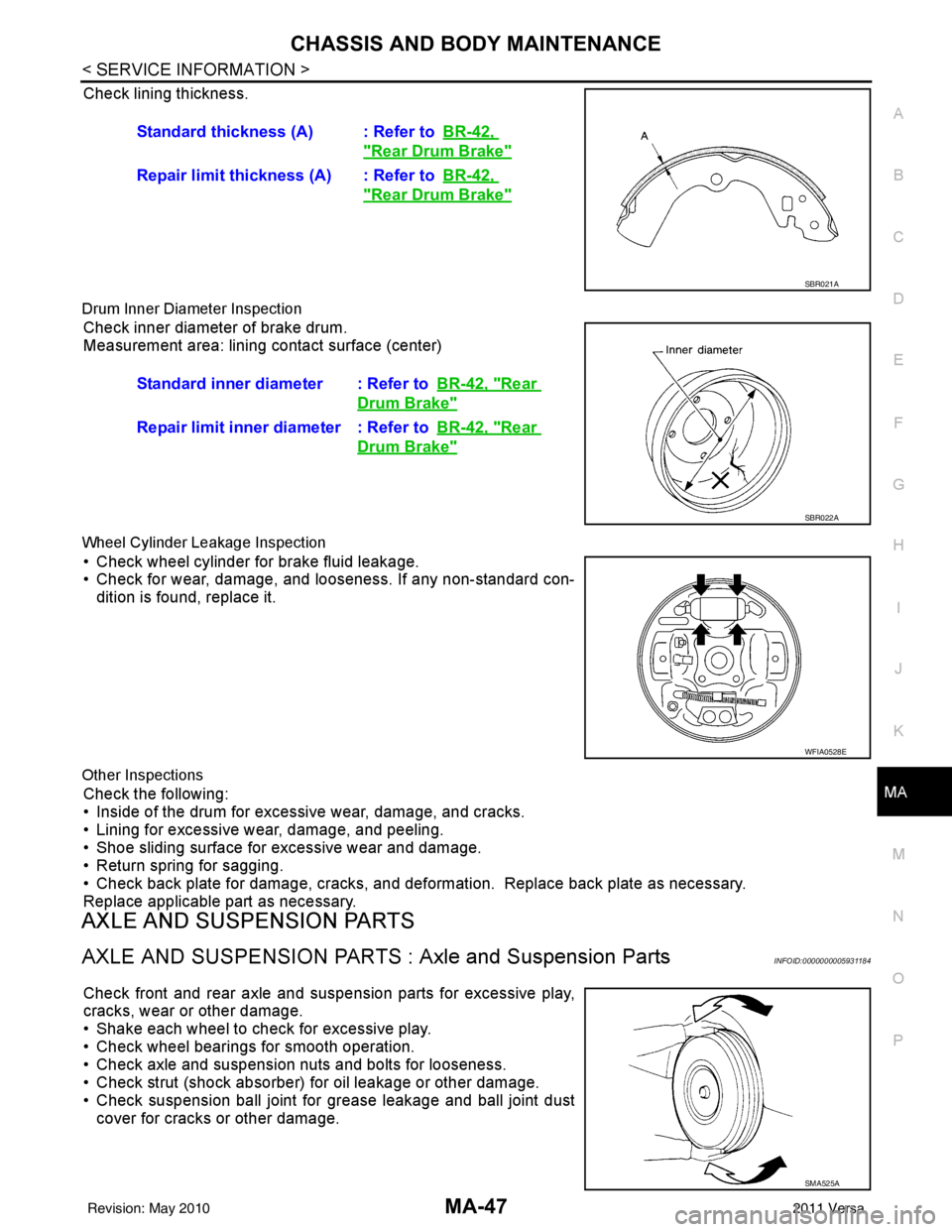
Check lining thickness.
Drum Inner Diameter Inspection
Check inner diameter of brake drum.
Measurement area: lining contact surface (center)
Wheel Cylinder Leakage Inspection
• Check wheel cylinder for brake fluid leakage.
• Check for wear, damage, and looseness. If any non-standard con- dition is found, replace it.
Other Inspections
Check the following:
• Inside of the drum for excessive wear, damage, and cracks.
• Lining for excessive wear, damage, and peeling.
• Shoe sliding surface for excessive wear and damage.
• Return spring for sagging.
• Check back plate for damage, cracks, and deformation. Replace back plate as necessary.
Replace applicable part as necessary.
AXLE AND SUSPENSION PARTS
AXLE AND SUSPENSION PARTS : Axle and Suspension PartsINFOID:0000000005931184
Check front and rear axle and suspension parts for excessive play,
cracks, wear or other damage.
• Shake each wheel to check for excessive play.
• Check wheel bearings for smooth operation.
• Check axle and suspension nuts and bolts for looseness.
• Check strut (shock absorber) for oil leakage or other damage.
• Check suspension ball joint for grease leakage and ball joint dust
cover for cracks or other damage. Standard thickness (A) : Refer to
BR-42,
"Rear Drum Brake"
Repair limit thickness (A) : Refer toBR-42,
"Rear Drum Brake"
SBR021A
Standard inner diameter : Refer toBR-42, "Rear
Drum Brake"
Repair limit inner diameter : Refer toBR-42, "Rear
Drum Brake"
SBR022A
WFIA0528E
SMA525A
Revision: May 2010 2011 Versa
Page 3417 of 3787
PARKING BRAKE CONTROLPB-5
< SERVICE INFORMATION >
C
DE
G H
I
J
K L
M A
B
PB
N
O P
PARKING BRAKE CONTROL
On-Vehicle ServiceINFOID:0000000005929649
OPERATION
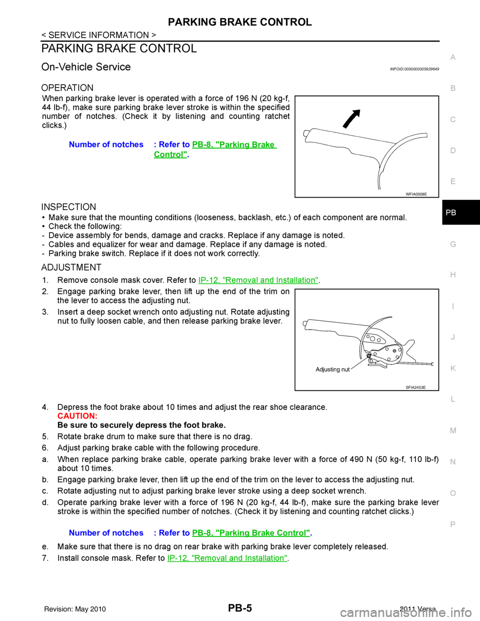
When parking brake lever is operated with a force of 196 N (20 kg-f,
44 lb-f), make sure parking brake le ver stroke is within the specified
number of notches. (Check it by listening and counting ratchet
clicks.)
INSPECTION
• Make sure that the mounting conditions (looseness, backlash, etc.) of each component are normal.
• Check the following:
- Device assembly for bends, damage and cracks. Replace if any damage is noted.
- Cables and equalizer for wear and damage. Replace if any damage is noted.
- Parking brake switch. Replace if it does not work correctly.
ADJUSTMENT
1. Remove console mask cover. Refer to IP-12, "Removal and Installation".
2. Engage parking brake lever, then lift up the end of the trim on the lever to access the adjusting nut.
3. Insert a deep socket wrench onto adjusting nut. Rotate adjusting nut to fully loosen cable, and then release parking brake lever.
4. Depress the foot brake about 10 ti mes and adjust the rear shoe clearance.
CAUTION:
Be sure to securely depress the foot brake.
5. Rotate brake drum to make sure that there is no drag.
6. Adjust parking brake cable with the following procedure.
a. When replace parking brake cable, operate parking br ake lever with a force of 490 N (50 kg-f, 110 lb-f)
about 10 times.
b. Engage parking brake lever, then lift up the end of the trim on the lever to access the adjusting nut.
c. Rotate adjusting nut to adjust parking brake lever stroke using a deep socket wrench.
d. Operate parking brake lever with a force of 196 N (20 kg-f, 44 lb-f), make sure the parking brake lever
stroke is within the specified number of notches. (Check it by listening and counting ratchet clicks.)
e. Make sure that there is no drag on rear brake with parking brake lever completely released.
7. Install console mask. Refer to IP-12, "
Removal and Installation".
Number of notches : Refer to
PB-8, "
Parking Brake
Control".
WFIA0508E
SFIA2453E
Number of notches : Refer to PB-8, "Parking Brake Control".
Revision: May 2010 2011 Versa
Page 3418 of 3787
PB-6
< SERVICE INFORMATION >
PARKING BRAKE CONTROL
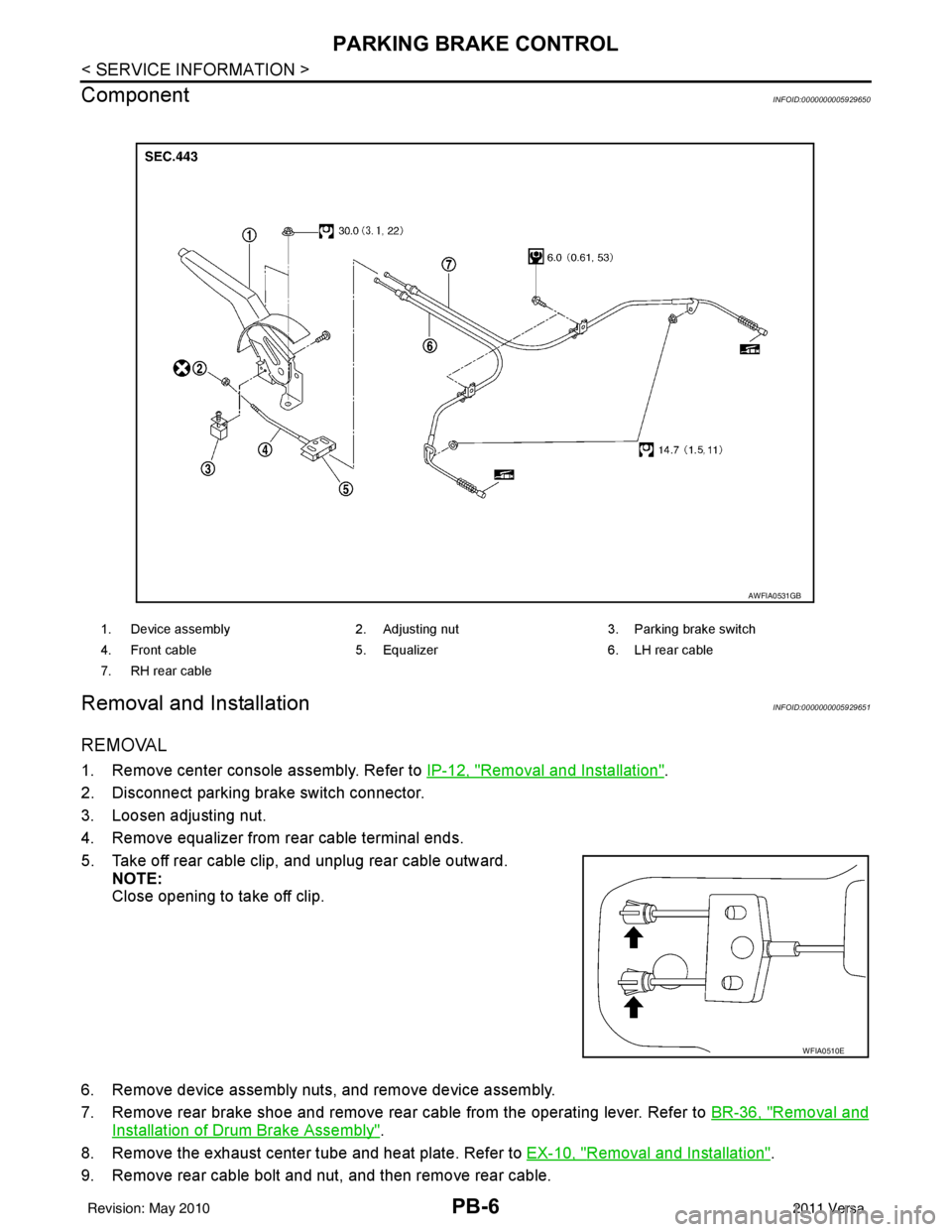
Component
INFOID:0000000005929650
Removal and InstallationINFOID:0000000005929651
REMOVAL
1. Remove center console assembly. Refer to IP-12, "Removal and Installation".
2. Disconnect parking brake switch connector.
3. Loosen adjusting nut.
4. Remove equalizer from rear cable terminal ends.
5. Take off rear cable clip, and unplug rear cable outward. NOTE:
Close opening to take off clip.
6. Remove device assembly nuts, and remove device assembly.
7. Remove rear brake shoe and remove rear cable from the operating lever. Refer to BR-36, "
Removal and
Installation of Drum Brake Assembly".
8. Remove the exhaust center tube and heat plate. Refer to EX-10, "
Removal and Installation".
9. Remove rear cable bolt and nut, and then remove rear cable.
1. Device assembly 2. Adjusting nut3. Parking brake switch
4. Front cable 5. Equalizer6. LH rear cable
7. RH rear cable
AWFIA0531GB
WFIA0510E
Revision: May 2010 2011 Versa
Page 3522 of 3787
WHEEL HUBRAX-7
< SERVICE INFORMATION >
CEF
G H
I
J
K L
M A
B
RAX
N
O P
Do not pull on wheel sensor harness.
3. Remove the brake drum only. Refer to BR-36, "
Removal and Installation of Drum Brake Assembly".
4. Remove wheel hub and bearing assembly bolts, and then remove wheel hub and bearing assembly from vehicle.
5. Suspend back plate with suitable wire, or if necessary, remove back plate using the following procedure. 1. Remove parking brake rear cable from back plate. Refer to PB-6, "
Removal and Installation".
2. Separate brake tube from wheel cylinder. Refer to BR-12, "
Rear Brake Tube and Hose".
INSPECTION AFTER REMOVAL
Check for any deformity, cracks, or other damage on the wheel hub assembly, replace if necessary.
CAUTION:
The wheel hub assembly does not requ ire maintenance. If any of the following symptoms are noted,
replace the wheel hub assembly.
• Growling noise is emitted from the wheel hub bearing during operation.
• Wheel hub bearing drags or turns roughly.
INSTALLATION
Installation is in the reverse order of removal.
Revision: May 2010 2011 Versa
Page 3565 of 3787
RSU-12
< SERVICE INFORMATION >
REAR SUSPENSION BEAM
REAR SUSPENSION BEAM
Removal and InstallationINFOID:0000000005931090
REMOVAL
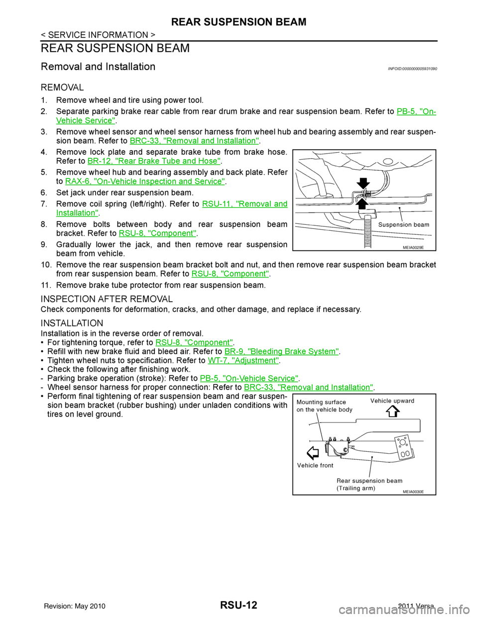
1. Remove wheel and tire using power tool.
2. Separate parking brake rear cable from rear drum brake and rear suspension beam. Refer to PB-5, "
On-
Vehicle Service".
3. Remove wheel sensor and wheel sensor harness from wheel hub and bearing assembly and rear suspen-
sion beam. Refer to BRC-33, "
Removal and Installation".
4. Remove lock plate and separate brake tube from brake hose. Refer to BR-12, "
Rear Brake Tube and Hose".
5. Remove wheel hub and bearing assembly and back plate. Refer to RAX-6, "
On-Vehicle Inspection and Service".
6. Set jack under rear suspension beam.
7. Remove coil spring (left/right). Refer to RSU-11, "
Removal and
Installation".
8. Remove bolts between body and rear suspension beam bracket. Refer to RSU-8, "
Component".
9. Gradually lower the jack, and then remove rear suspension beam from vehicle.
10. Remove the rear suspension beam bracket bolt and nut, and then remove rear suspension beam bracket
from rear suspension beam. Refer to RSU-8, "
Component".
11. Remove brake tube protector from rear suspension beam.
INSPECTION AFTER REMOVAL
Check components for deformation, cracks, and other damage, and replace if necessary.
INSTALLATION
Installation is in the reverse order of removal.
• For tightening torque, refer to RSU-8, "
Component".
• Refill with new brake fluid and bleed air. Refer to BR-9, "
Bleeding Brake System".
• Tighten wheel nuts to specification. Refer to WT-7, "
Adjustment".
• Check the following after finishing work.
- Parking brake operation (stroke): Refer to PB-5, "
On-Vehicle Service".
- Wheel sensor harness for proper connection: Refer to BRC-33, "
Removal and Installation".
• Perform final tightening of rear suspension beam and rear suspen-
sion beam bracket (rubber bushing) under unladen conditions with
tires on level ground.
MEIA0029E
MEIA0030E
Revision: May 2010 2011 Versa