2011 NISSAN TIIDA Back door lock
[x] Cancel search: Back door lockPage 512 of 3787

BL-2
Keyfob Function (Lock) Check ...............................82
Keyfob Function (Unlock) Check ............................82
ID Code Entry Procedure .................................... ...83
Keyfob Battery Replacement ............................... ...85
Removal and Installation of Remote Keyless Entry
Receiver .............................................................. ...
85
INTELLIGENT KEY SYSTEM ............................86
Component Parts and Harness Connector Loca-
tion ....................................................................... ...
86
System Description .................................................88
CAN Communication System Description ..............95
Schematic ............................................................ ...96
Wiring Diagram - I/KEY - ..................................... ...98
Intelligent Key Unit Har ness Connector Terminal
Layout .................................................................. ..
108
Terminal and Reference Value for Intelligent Key
Unit ........................................................................
108
Steering Lock Solenoid Harness Connector Ter-
minal Layout ..........................................................
110
Terminal and Reference Value for Steering Lock
Solenoid .................................................................
110
Terminal and Reference Value for BCM ................111
Trouble Diagnosis Procedure ................................115
CONSULT-III Functions (INTELLIGENT KEY) ......117
CONSULT-III Application Item ............................. ..117
Trouble Diagnosis Symptom Chart ........................119
CAN Communication System Inspection ...............126
Power Supply and Ground Circuit Inspection ........126
Key Switch (Intelligent Key Unit Input) Check .......127
Key Switch (BCM Input) Check .............................128
Ignition Knob Switch Check ................................. ..129
Door Switch Check (Hatchback) ............................131
Door Switch Check (Sedan) ..................................134
Door Request Switch Check ..................................135
Back Door Request Switch Check (Hatchback) ....137
Trunk Opener Request Switch Check (Sedan) ... ..138
Unlock Sensor Check ............................................140
Intelligent Key Warning Buzzer(s) Check ..............142
Outside Key Antenna (Dri ver Side and Passenger
Side) Check ......................................................... ..
143
Outside Key Antenna (Rear Bumper) Check .........144
Inside Key Antenna Check ....................................146
Steering Lock Solenoid Check ............................ ..147
Key Interlock Solenoid (With M/T) Check ..............149
Ignition Switch Position Check ............................ ..150
Stop Lamp Switch Check (With CVT or A/T) ....... ..150
Stop Lamp Switch Check (With M/T) .....................152
CVT or A/T Shift Selector (Park Position Switch)
Check .................................................................. ..
153
"P-SHIFT" Warning Lamp (With CVT or A/T)
Check ....................................................................
154
"LOCK" Warning Lamp (With M/T) Check .............155
"KEY" Warning Lamp (RED) Check ......................155
"KEY" Warning Lamp (G REEN) Check .................155
Check Warning Chime in Combination Meter ........156
Hazard Function Check .........................................156
Horn Function Check .... .........................................157
Headlamp Function Chec k ....................................157
Intelligent Key Battery Re placement .....................158
Remote Keyless Entry Func tion ............................158
Removal and Installation of Intelligent Key Unit ... .158
DOOR ...............................................................160
Fitting Adjustment ................................................ .160
Removal and Installation .......................................163
Back Door Stay Disposal ..................................... .166
FRONT DOOR LOCK .......................................167
Component Parts Location .................................. .167
Removal and Installation .......................................167
REAR DOOR LOCK ....................................... ..170
Component Parts Location .................................. .170
Removal and Installation .......................................170
BACK DOOR LOCK ....................................... ..173
Component Parts and Harness Connector Loca-
tion ....................................................................... .
173
System Description ...............................................173
Wiring Diagram - B/DOOR - ..................................174
Terminal and Reference Value for BCM ...............176
Terminal and Reference Value for Intelligent Key
Unit ....................................................................... .
180
CONSULT-III Function (BCM) ..............................182
Work Flow .............................................................183
Trouble Diagnosis Chart by Symptom ..................183
BCM Power Supply and Ground Circuit Inspection
.
183
Check Back Door Opener Switch Circuit (Without
Intelligent Key or Power Windows) ...................... .
184
Check Back Door Opener Switch Circuit (Without
Intelligent Key, with Power Windows) .................. .
187
Check Back Door Opener Switch Circuit (With In-
telligent Key) ........................................................ .
189
Check Back Door Lock Assembly (Actuator) Cir-
cuit ........................................................................
191
Removal and Installation .......................................193
TRUNK LID ..................................................... ..195
Fitting Adjustment ................................................ .195
Trunk Lid Assembly ..............................................195
Trunk Lid Lock ......................................................196
Trunk Lid Striker ....................................................196
TRUNK LID OPENER .......................................198
Component Parts and Harness Connector Loca-
tion ....................................................................... .
198
System Description ...............................................198
Wiring Diagram - TLID - ........................................199
Terminal and Reference Value for BCM ...............201
Terminal and Reference Value for Intelligent Key
Unit ....................................................................... .
205
CONSULT-III Function (BCM) ..............................207
Work Flow .............................................................208
Trouble Diagnosis Chart by Symptom ..................208
BCM Power Supply and Ground Circuit Inspection
.
208
Revision: May 2010 2011 Versa
Page 533 of 3787

POWER DOOR LOCK SYSTEMBL-23
< SERVICE INFORMATION >
C
DE
F
G H
J
K L
M A
B
BL
N
O P
System DescriptionINFOID:0000000005929283
Power is supplied at all times
• through 40A fusible link (letter g, located in the fuse and fusible link box)
• to BCM terminal 70
• through 10A fuse [No. 8, located in the fuse block (J/B)]
• to BCM terminal 57
• through 10A fuse [No. 14, located in the fuse block (J/B)]
• to key switch terminal 2 (without Intelligent Key system)
• through 10A fuse [No. 31, located in the fuse block (J/B)]
• to key switch and ignition knob switch terminals 2 and 4 (with Intelligent Key system).
When key switch is ON (key is inserted in ignition key cylinder), power is supplied
• through key switch terminal 1 (without Intelligent Key system) or key switch and ignition knob terminal 1 (with Intelligent Key system)
• to BCM terminal 37.
Ground is supplied
• to BCM terminal 67
• through body grounds M57 and M61.
LOCK OPERATION
When the door is locked with main power window and door lock/unlock switch, ground is supplied
• to BCM terminal 45
• through main power window and door lock and unlock switch terminals 17 and 18
• through body grounds M57 and M61.
When the door is locked with power window and door lock/unlock switch RH, ground is supplied
• to BCM terminal 45
• through power window and door lock and unlock switch RH terminals 1 and 3
• through body grounds M57 and M61.
When the door is locked with front door lock assemb ly LH (key cylinder switch), ground is supplied
• to BCM terminal 8
• through front door lock assembly LH (key cylinder switch) terminals 4 and 6
• through body grounds M57 and M61.
UNLOCK OPERATION
When the door is unlocked with main power window and door lock/unlock switch, ground is supplied
• to BCM terminal 46
• through main power window and door lock/unlock switch terminals 6 and 17
• through body grounds M57 and M61.
When the door is unlocked with power window and door lock/unlock switch RH, ground is supplied
• to BCM terminal 46
• through power window and door lock and unlock switch RH terminals 2 and 3
• through body grounds M57 and M61.
When the door is unlocked with front door lock assemb ly LH (key cylinder switch), ground is supplied
• to BCM terminal 7
• through front door lock assembly LH (key cylinder switch) terminals 4 and 5
1. BCM M18, M19, M20
(view with glove box removed) 2. Intelligent Key unit M52
(if equipped) 3. Front door lock assembly LH (key cyl-
inder switch) D14
4. Front door switch LH B8, RH B108 5. Front door lock assembly LH (actuator) D14
Front door lock assembly RH (actuator)
D1146. Rear door switch LH B6, RH B116
7. Rear door lock actuator LH D205 RH D305 8. Key switch and ignition knob switch M73
(with A/T or CVT and Intelligent Key) 9. Key switch and ignition knob switch
M73 (with M/T and Intelligent Key)
10. Key switch and key lock solenoid M27 (without Intelligent key) 11. Main power window and door lock/un-
lock switch D7, D8
Power window and door lock/unlock
switch RH D105 12. Fuse block (with Intelligent Key)
(view with instrument panel LH re-
moved)
13. Passenger select unlock relay M2 (with Intelligent Key) 14. Back door lock assembly (back door
switch) D405 (hatchback view with back
door open) 15. Combination meter M24
Revision: May 2010
2011 Versa
Page 534 of 3787

BL-24
< SERVICE INFORMATION >
POWER DOOR LOCK SYSTEM
• through body grounds M57 and M61.
When the front door switch LH is ON (door is OPEN), ground is supplied
• to BCM terminal 47
• through front door switch LH terminal 2
• through front door switch LH case ground.
When the front door switch RH is ON (door is OPEN), ground is supplied
• to BCM terminal 12
• through front door switch RH terminal 2
• through front door switch RH case ground.
When the rear door switch LH is ON (door is OPEN), ground is supplied
• to BCM terminal 48
• through rear door switch LH terminal 1
• through rear door switch LH case ground.
When the rear door switch RH is ON (door is OPEN), ground is supplied
• to BCM terminal 13
• through rear door switch RH terminal 1
• through rear door switch RH case ground.
When the back door lock assembly (back door switch) ( hatchback) is ON (back door is OPEN), ground is sup-
plied
• to BCM terminal 43
• through back door lock assembly (back door switch) terminals 3 and 4
• through body grounds B117, B132 and D402.
OUTLINE
Functions available by operating the inside door lock and unlock switches
• Interlocked with the locking operation of door lock and unlock switch, door lock actuators of all doors are
locked.
• Interlocked with the unlocking operation of door lock and unlock switch, door lock actuators of all doors are
unlocked.
Functions available by operating the front door lock assembly LH (key cylinder switch)
• Interlocked with the locking operation of front door lock assembly LH (key cylinder switch), door lock actua-
tors of all doors are locked.
• When front door lock assembly LH (key cylinder switch) is unlocked, front door lock assembly LH (actuator)
is unlocked.
• When front door lock assembly LH (key cylinder swit ch) is unlocked for the second time within 5 seconds
after the first operation, front door lock assembly RH (actuator), rear door lock actuator LH and rear door
lock actuator RH are unlocked.
Key reminder door system
When door lock and unlock switch is operated to lock doors with ignition key inserted in key cylinder and any
door open, all door lock actuators are locked and then unlocked.
AUTOMATIC DOOR LOCKS (LOCK OPERATION)
The interlock door lock function is the function that locks all doors linked with the vehicle speed.
Vehicle Speed Sensing Auto Door Lock*1
All doors are locked when the vehicle speed reaches 24 km/h (15 MPH) or more.
BCM outputs the lock signal to all door lock actuators when it detects that the ignition switch is turned ON, all
doors are closed and the vehicle speed received from the combination meter via CAN communication
becomes 15 MPH (24 km/h) or more.
If a door is opened and closed at any time during one ignition cycle (OFF → ON), even after initial auto door
lock has taken place, the BCM will relock all doors when the vehicle speed reaches 15 MPH (24 km/h) or more
again.
Setting change of Automatic Door Locks (LOCK) Function
The lock operation setting of the autom atic door locks function can be changed.
With CONSULT-III
The ON/OFF switching of the automatic door locks (LOC K) function and the type selection of the automatic
door locks (LOCK) function can be performed at the WO RK SUPPORT setting of CONSULT-III. Refer to BL-
41, "CONSULT-III Function (BCM)".
Without CONSULT- III
The automatic door locks (LOCK) function can be swit ched ON/OFF by performing the following operation.
Revision: May 2010 2011 Versa
Page 549 of 3787
POWER DOOR LOCK SYSTEMBL-39
< SERVICE INFORMATION >
C
DE
F
G H
J
K L
M A
B
BL
N
O P
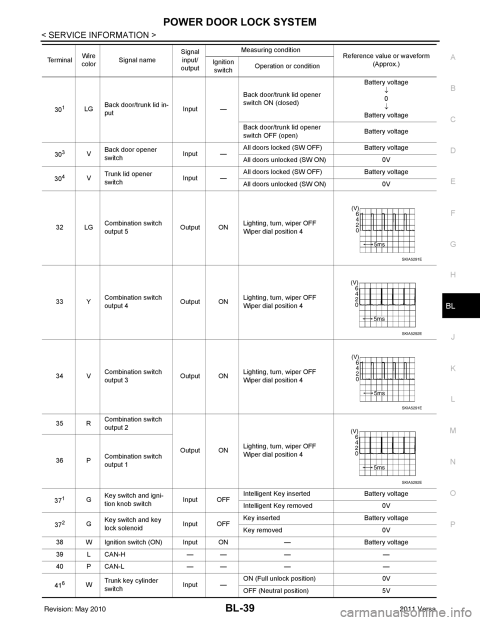
301LG Back door/trunk lid in-
put Input —Back door/trunk lid opener
switch ON (closed) Battery voltage
↓0
↓
Battery voltage
Back door/trunk lid opener
switch OFF (open) Battery voltage
30
3V Back door opener
switch
Input —All doors locked (SW OFF)
Battery voltage
All doors unlocked (SW ON) 0V
30
4V Trunk lid opener
switch
Input —All doors locked (SW OFF)
Battery voltage
All doors unlocked (SW ON) 0V
32 LG Combination switch
output 5 Output ONLighting, turn, wiper OFF
Wiper dial position 4
33 Y Combination switch
output 4 Output ON
Lighting, turn, wiper OFF
Wiper dial position 4
34 V Combination switch
output 3
Output ONLighting, turn, wiper OFF
Wiper dial position 4
35 R Combination switch
output 2
Output ONLighting, turn, wiper OFF
Wiper dial position 4
36 P Combination switch
output 1
37
1G Key switch and igni-
tion knob switch Input OFFIntelligent Key inserted
Battery voltage
Intelligent Key removed 0V
37
2G Key switch and key
lock solenoid Input OFFKey inserted
Battery voltage
Key removed 0V
38 W Ignition switch (ON) Input ON —Battery voltage
39 L CAN-H — —— —
40 P CAN-L — —— —
41
6W Trunk key cylinder
switch
Input —ON (Full unlock position)
0V
OFF (Neutral position) 5V
Te r m i n a l
Wire
color Signal name Signal
input/
output Measuring condition
Reference value or waveform
(Approx.)
Ignition
switch Operation or condition
SKIA5291E
SKIA5292E
SKIA5291E
SKIA5292E
Revision: May 2010
2011 Versa
Page 550 of 3787
BL-40
< SERVICE INFORMATION >
POWER DOOR LOCK SYSTEM
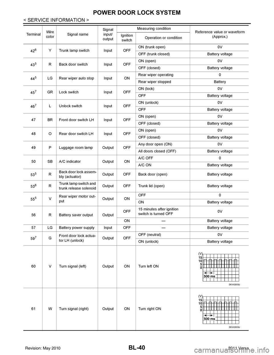
426Y Trunk lamp switch Input OFFON (trunk open)
0V
OFF (trunk closed) Battery voltage
43
5R Back door switch Input OFF ON (open) 0V
OFF (closed)
Battery voltage
44
5LG Rear wiper auto stop Input ON Rear wiper operating 0
Rear wiper stopped
Battery
45
7GR Lock switch Input OFFON (lock)
0V
OFF Battery voltage
46
7L Unlock switch Input OFFON (unlock)
0V
OFF Battery voltage
47 BR Front door switch LH Input OFF ON (open)
0V
OFF (closed) Battery voltage
48 O Rear door switch LH Input OFF ON (open)
0V
OFF (closed) Battery voltage
49 P Luggage room lamp Output OFF Any door open (ON)
0V
All doors closed (OFF) Battery voltage
50 SB A/C indicator Output ONA/C OFF
0
A/C ON Battery voltage
53
5R Back door lock assem-
bly (actuator)
Output OFF Back door (open)
Battery voltage
53
6R Trunk lamp switch and
trunk release solenoid Output OFF Trunk lid (open)
Battery voltage
55
5V Rear wiper motor out-
put
Output ONOFF
0
ON Battery voltage
56 R Battery saver output Output OFF
15 minutes after ignition
switch is turned OFF 0V
ON — Battery voltage
57 LG Battery power supply Input OFF —Battery voltage
59
7G Front door lock actua-
tor LH (unlock)
Output OFFOFF (neutral)
0V
ON (unlock) Battery voltage
60 V Turn signal (left) Output ON Turn left ON
61 W Turn signal (right) Output ON Turn right ON
Te r m i n a l
Wire
color Signal name Signal
input/
output Measuring condition
Reference value or waveform
(Approx.)
Ignition
switch Operation or condition
SKIA3009J
SKIA3009J
Revision: May 2010
2011 Versa
Page 551 of 3787

POWER DOOR LOCK SYSTEMBL-41
< SERVICE INFORMATION >
C
DE
F
G H
J
K L
M A
B
BL
N
O P
1: With Intelligent Key
2: Without Intelligent Key
3: Hatchback without Intelligent Key
4: Sedan without Intelligent Key
5: Hatchback
6: Sedan
7: With power door locks
8: With power windows
Work FlowINFOID:0000000005929290
1. Check the symptom and customer's requests.
2. Understand the outline of system. Refer to BL-23, "
System Description" .
3. According to the trouble diagnosis chart, repair or replace the cause of the malfunction. Refer to BL-119,
"Trouble Diagnosis Symptom Chart" .
4. Does power door lock system operate normally? OK: GO TO 5, NG: GO TO 3.
5. Inspection End.
CONSULT-III Function (BCM)INFOID:0000000005929291
CONSULT-III can display each diagnostic item using the diagnostic test modes shown following.
63 BR Interior room lamp Output OFF Any door
switchON (open)
0V
OFF (closed) Battery voltage
65
7SB All door lock actuators
(lock) Output OFFOFF (neutral)
0V
ON (lock) Battery voltage
66
7G Front door lock actua-
tor RH, rear door lock
actuators LH/RH (un-
lock) Output OFFOFF (neutral)
0V
ON (unlock) Battery voltage
67 B Ground Input ON—0V
68
8L Power window power
supply (RAP)
Output —Ignition switch ON
Battery voltage
Within 45 seconds after igni-
tion switch OFF Battery voltage
More than 45 seconds after ig-
nition switch OFF 0V
When front door LH or RH is
open or power window timer
operates 0V
69
8P Battery power supply OutputOFF
— Battery voltage
70 Y Battery power supply Input OFF —Battery voltage
Te r m i n a l
Wire
color Signal name Signal
input/
output Measuring condition
Reference value or waveform
(Approx.)
Ignition
switch Operation or condition
Diagnostic mode
Description
WORK SUPPORT Supports inspections and adjustments. Commands are transmitted to the BCM for setting the status
suitable for required operation, input/output signals are received from the BCM and received date
is displayed.
DATA MONITOR Displays BCM input/output data in real time. ACTIVE TEST Operation of electrical loads can be checked by sending drive signal to them.
SELF DIAGNOSTIC RESULT Displays BCM self-diagnosis results.
CAN DIAG SUPPORT MNTR The result of transmit/receive diagnosis of CAN communication can be read.
Revision: May 2010 2011 Versa
Page 552 of 3787

BL-42
< SERVICE INFORMATION >
POWER DOOR LOCK SYSTEM
WORK SUPPORT
DATA MONITOR
*: With Remote Keyless Entry system
**: With Intelligent Key system
ACTIVE TEST
ECU IDENTIFICATION BCM part number can be read.CONFIGURATION Performs BCM configuration read/write functions.Diagnostic mode
Description
Work item Description
DOOR LOCK-UNLOCK SET Select unlock mode can be changed in this mode. Selects ON-OFF of select unlock mode.
ANTI-LOCK OUT SET Key reminder door mode can be changed in this mode. Selects ON-OFF of key reminder door mode.
AUTOMATIC DOOR LOCK
SELECT The following modes can be selected for automatic door lock function:
• VH SPD: All doors are locked when vehicle speed is more than 15 MPH (25 km/h) (factory setting).
• SHIFT OUT OF P: Not allowed.
AUTOMATIC DOOR UN-
LOCK SELECT The following modes can be selected for automatic door unlock function:
• MODE1: Allowed (factory setting for vehicles with Intelligent Key). All doors are unlocked when
the ignition switch is turned from ON to OFF.
• MODE2: Not allowed.
• MODE3: Allowed (factory setting for vehicles without Intelligent Key). All doors are unlocked when the key is removed from the ignition switch.
• MODE4: Not allowed.
• MODE5: Not allowed.
• MODE6: Not allowed.
AUTOMATIC LOCK/UNLOCK
SELECT •ON
•OFF
Monitor item
Content
IGN ON SW Indicates [ON/OFF] condition of ignition switch in ON position.
KEY ON SW Indicates [ON/OFF] condition of key switch.
CDL LOCK SW Indicates [ON/OFF] condition of lock signal from door lock and unlock switch.
CDL UNLOCK SW Indicates [ON/OFF] condition of unlock signal from door lock and unlock switch.
DOOR SW-DR Indicates [ON/OFF] condition of front door switch LH.
DOOR SW-AS Indicates [ON/OFF] condition of front door switch RH.
DOOR SW-RR Indicates [ON/OFF] condition of rear door switch RH.
DOOR SW-RL Indicates [ON/OFF] condition of rear door switch LH.
BACK DOOR SW Indicates [ON/OFF] condition of back door switch.
KEY CYL LK-SW Indicates [ON/OFF] condition of lock signal from key cylinder.
KEY CYL UN-SW Indicates [ON/OFF] condition of unlock signal from key cylinder.
KEYLESS LOCK* Indicates [ON/OFF] condition of lock signal from keyfob.
KEYLESS UNLOCK* Indicates [ON/OFF] condition of unlock signal from keyfob.
I-KEY LOCK** Indicates [ON/OFF] condition of lock signal from door request switch.
I-KEY UNLOCK** Indicates [ON/OFF] condition of unlock signal from door request switch.
Test item Content
DOOR LOCK This test is able to check door lock operation [ALL LCK/ALL ULK/DR UNLK/OTR ULK].
Revision: May 2010 2011 Versa
Page 553 of 3787

POWER DOOR LOCK SYSTEMBL-43
< SERVICE INFORMATION >
C
DE
F
G H
J
K L
M A
B
BL
N
O P
Trouble Diagnosis Symptom ChartINFOID:0000000005929292
BCM Power Supply and Gr ound Circuit InspectionINFOID:0000000006215770
1.CHECK FUSES AND FUSIBLE LINK
• Check 40A fusible link (letter g , located in the fuse and fusible link box).
• Check 10A fuses [No. 6, 8 and 20, lo cated in the fuse block (J/B)].
OK or NG
OK >> GO TO 2.
NG >> If fuse is blown, be sure to eliminate cause of malfunction before installing new fuse. Refer to PG-
4, "Schematic" .
2.CHECK BCM POWER SUPPLY CIRCUIT
1. Turn ignition switch OFF.
2. Disconnect BCM.
3. Check voltage between BCM connectors and ground.
Symptom Repair orderRefer to page
Key reminder door function does not operate properly. 1. BCM power supply and ground circuit check
BCS-16
2. Door switch check (hatchback) BL-44
3. Door switch check (sedan)BL-47
4. Key switch (insert) checkBL-48
5. Replace BCM.BCS-19
Power door lock does not operate with door lock and un-
lock switch on main power window and door lock/unlock
switch or power window and door lock/unlock switch RH1. Door lock/unlock switch check
BL-49
2. Replace BCM.BCS-19
One or both rear door lock actuators do not operate. 1. Passenger select unlock relay circuit check BL-56
Front door lock assembly LH (actuator) does not operate. 1. Front door lock assembly LH (actuator) checkBL-52
Specific door lock actuator does not operate.1. Door lock actuator check (Front RH, Rear LH/RH) BL-54
Power door lock does not operate with front door key cyl-
inder switch operation.1. Front door key cylinder switch check
BL-54
2. Replace BCM.BCS-19
All power door locks do not operate.1. BCM power supply and ground circuit check
BCS-162. Door lock/unlock switch check BL-49
3. Replace BCM.BCS-19
Vehicle speed sensing auto door LOCK operation does
not operate.1. Ensure automatic door lock/unlock function (lock
operation) is enabled.
BL-41
2. Check combination meter vehicle speed signal.
DI-16
3. Check intermittent incident.GI-22
Ignition OFF interlock auto door UNLOCK function does
not operate.1. Ensure automatic door lock/unlock function (unlock
operation) is enabled.
BL-41
2. Check BCM for DTCs.
BCS-18
3. Check intermittent incident. GI-22
LIIA2415E
Revision: May 2010 2011 Versa