2011 NISSAN TIIDA Back door lock
[x] Cancel search: Back door lockPage 580 of 3787

BL-70
< SERVICE INFORMATION >
REMOTE KEYLESS ENTRY SYSTEM
CONSULT-III APPLICATION ITEMS
Work Support
HAZARD LAMP SET
AUTO LOCK SET
PANIC ALARM SET
TRUNK OPEN SET
Data Monitor
Diagnostic modeDescription
WORK SUPPORT Supports inspections and adjustments. Commands are transmitted to the BCM for setting
the status suitable for required operation, input/output signals are received from the BCM
and received date is displayed.
DATA MONITOR Displays BCM input/output data in real time.
ACTIVE TEST Operation of electrical loads can be checked by sending drive signal to them.
SELF DIAGNOSTIC RESULT Displays BCM self-diagnosis results. CAN DIAG SUPPORT MNTR The result of transmit/receive diagnosis of CAN communication can be read. ECU IDENTIFICATION BCM part number can be read.CONFIGURATION Performs BCM configuration read/write functions.
Te s t I t e m D e s c r i p t i o n
HORN CHIRP SET Horn chirp (On/Off) when keyfob Lock or Unlock is pressed can be selected.
REMO CONT ID REGIST Keyfob ID code can be registered.
REMO CONT ID ERASER Keyfob ID code can be erased.
REMO CONT ID CONFIR Keyfob ID code can be checked whether it is registered or not.
MODE 1 MODE 2MODE 3 MODE 4
Hazard lamp operation mode NothingUnlock only Lock only Lock and Unlock
MODE 1 MODE 2MODE 3
Auto locking function 30 secondsNothing1 minutes
MODE 1 MODE 2MODE 3
Keyfob operation 0.5 secondsNothing1.5 seconds
MODE 1 MODE 2MODE 3
Keyfob operation 0.5 secondsNothing1.5 seconds
Monitored Item Description
IGN ON SW Indicates [ON/OFF] condition of ignition switch in ON position.
KEY ON SW Indicates [ON/OFF] condition of key switch.
ACC ON SW Indicates [ON/OFF] condition of ignition switch in ACC position.
KEYLESS LOCK Indicates [ON/OFF] condition of lock signal from keyfob.
KEYLESS UNLOCK Indicates [ON/OFF] condition of unlock signal from keyfob.
KEYLESS PANIC Indicates [ON/OFF] condition of panic alarm signal from keyfob.
DOOR SW-DR Indicates [ON/OFF] condition of front door switch driver side.
DOOR SW-AS Indicates [ON/OFF] condition of front door switch passenger side.
DOOR SW-RR Indicates [ON/OFF] condition of rear door switch RH.
DOOR SW-RL Indicates [ON/OFF] condition of rear door switch LH.
TRNK OPN MNTR Indicates [ON/OFF] condition of trunk room lamp switch (sedan).
BACK DOOR SW Indicates [ON/OFF] condition of back door switch (hatchback).
CDL LOCK SW Indicates [ON/OFF] condition of lock signal from door lock and unlock switch.
Revision: May 2010 2011 Versa
Page 581 of 3787
REMOTE KEYLESS ENTRY SYSTEMBL-71
< SERVICE INFORMATION >
C
DE
F
G H
J
K L
M A
B
BL
N
O P
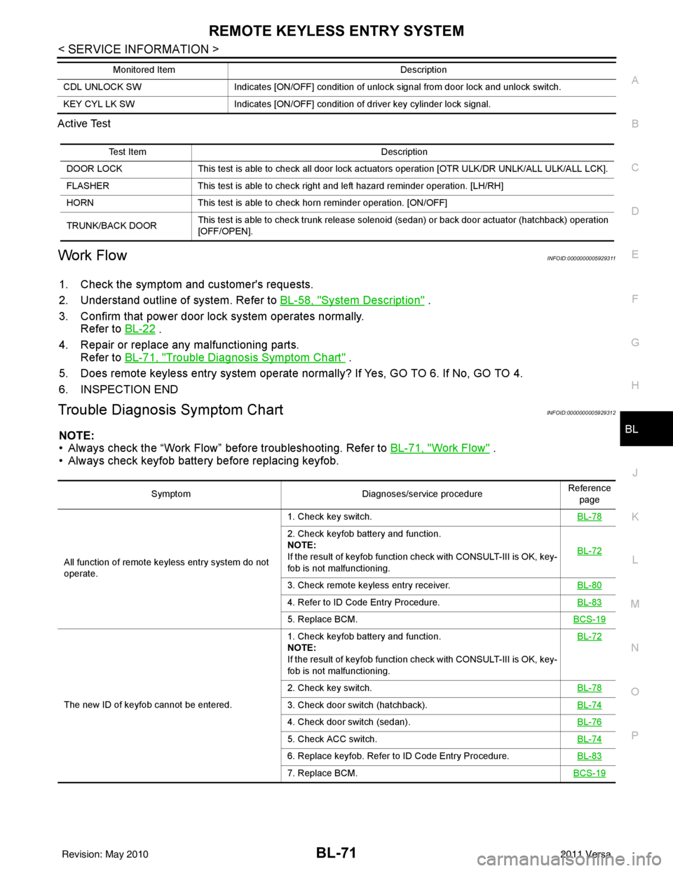
Active Test
Work FlowINFOID:0000000005929311
1. Check the symptom and customer's requests.
2. Understand outline of system. Refer to
BL-58, "
System Description" .
3. Confirm that power door lock system operates normally. Refer to BL-22
.
4. Repair or replace any malfunctioning parts. Refer to BL-71, "
Trouble Diagnosis Symptom Chart" .
5. Does remote keyless entry system operate normally? If Yes, GO TO 6. If No, GO TO 4.
6. INSPECTION END
Trouble Diagnosis Symptom ChartINFOID:0000000005929312
NOTE:
• Always check the “Work Flow” before troubleshooting. Refer to BL-71, "
Work Flow" .
• Always check keyfob battery before replacing keyfob.
CDL UNLOCK SW Indicates [ON/OFF] condition of unlock signal from door lock and unlock switch.
KEY CYL LK SW Indicates [ON/OFF] condition of driver key cylinder lock signal.
Monitored Item
Description
Test ItemDescription
DOOR LOCK This test is able to check all door lock actuators operation [OTR ULK/DR UNLK/ALL ULK/ALL LCK].
FLASHER This test is able to check right and left hazard reminder operation. [LH/RH]
HORN This test is able to check horn reminder operation. [ON/OFF]
TRUNK/BACK DOOR This test is able to check trunk release solenoid (sedan) or back door actuator (hatchback) operation
[OFF/OPEN].
Symptom
Diagnoses/service procedureReference
page
All function of remote keyless entry system do not
operate. 1. Check key switch.
BL-78
2. Check keyfob battery and function.
NOTE:
If the result of keyfob function check with CONSULT-III is OK, key-
fob is not malfunctioning.BL-72
3. Check remote keyless entry receiver.
BL-80
4. Refer to ID Code Entry Procedure.BL-83
5. Replace BCM.BCS-19
The new ID of keyfob cannot be entered.1. Check keyfob battery and function.
NOTE:
If the result of keyfob function check with CONSULT-III is OK, key-
fob is not malfunctioning.
BL-72
2. Check key switch.
BL-78
3. Check door switch (hatchback).BL-74
4. Check door switch (sedan).BL-76
5. Check ACC switch.BL-74
6. Replace keyfob. Refer to ID Code Entry Procedure.BL-83
7. Replace BCM.BCS-19
Revision: May 2010 2011 Versa
Page 582 of 3787

BL-72
< SERVICE INFORMATION >
REMOTE KEYLESS ENTRY SYSTEM
Keyfob Battery and Function Check
INFOID:0000000005929313
1.CHECK KEYFOB FUNCTION
With CONSULT-III
Check keyfob function in “DATA MONITOR” mode with CONSULT-III. When pushing each button of keyfob,
the corresponding monitor item should be turned as follows.
Without CONSULT-III
Door lock does not function with keyfob.
(Power door lock system is “OK”.) 1. Check keyfob function. (Lock)
NOTE:
If the result of keyfob function check with CONSULT-III is OK, key-
fob is not malfunctioning.
BL-822. Replace keyfob. Refer to ID Code Entry Procedure.
BL-83
3. Check door switch (hatchback).BL-74
4. Check door switch (sedan).BL-76
5. Replace BCM.BCS-19
Door unlock does not function with keyfob
(Power door lock system is “OK”)1. Check keyfob function. (Unlock)
BL-82
2. Replace keyfob. Refer to ID Code Entry Procedure.
NOTE:
If the result of keyfob function check with CONSULT-III is OK, key-
fob is not malfunctioning.BL-83
3. Replace BCM.
BCS-19
Hazard reminder does not activate properly when
pressing lock or unlock button of keyfob.1. Check hazard reminder mode.*
*: Hazard reminder mode can be changed.
First check the hazard reminder setting.
BL-69
2. Check hazard function.
BL-79
3. Replace BCM.BCS-19
Panic alarm does not activate when panic alarm but-
ton is continuously pressed.1. Check panic alarm mode.*
*: Panic alarm mode can be changed.
First check the panic alarm setting.
BL-69
2. Check keyfob battery and function.
NOTE:
If the result of keyfob function check with CONSULT-III is OK, key-
fob is not malfunctioning.BL-72
3. Check horn function.
BL-79
4. Check key switch.BL-78
5. Replace keyfob. Refer to ID Code Entry Procedure.BL-83
6. Replace BCM.BCS-19
Auto door lock operation does not activate properly.
(All other remote keyless entry system functions are
OK.)1. Check auto door lock operation mode.*
*: Auto door lock operation mode can be changed.
First check the auto door lock operation setting.
BL-69
2. Replace BCM.
BCS-19
Interior lamp operation does not activate properly.1. Check interior lamp operation.
BL-802. Replace BCM.BCS-19
SymptomDiagnoses/service procedureReference
page
Condition Monitor item
Pushing LOCK KEYLESS LOCK: ON
Pushing UNLOCK KEYLESS UNLOCK: ON
Pushing PANIC KEYLESS PANIC: ON
Revision: May 2010 2011 Versa
Page 584 of 3787
BL-74
< SERVICE INFORMATION >
REMOTE KEYLESS ENTRY SYSTEM
ACC Switch Circuit Check
INFOID:0000000005929314
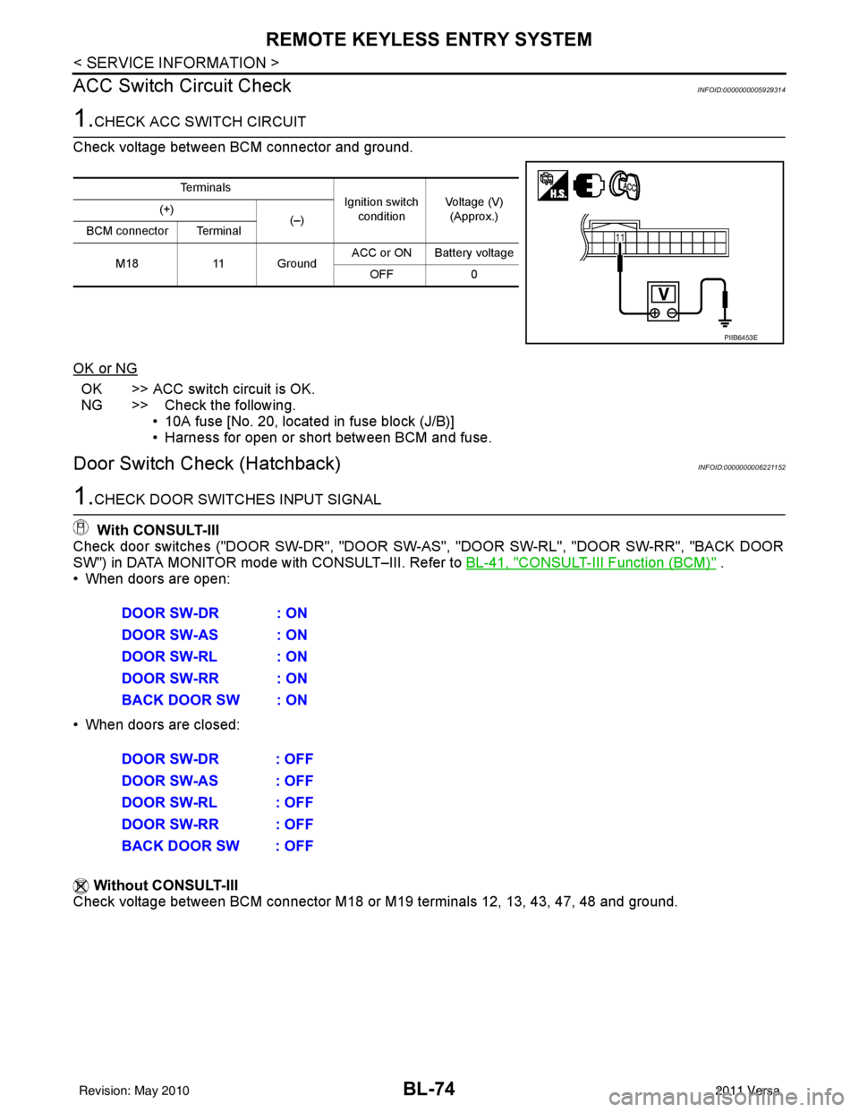
1.CHECK ACC SWITCH CIRCUIT
Check voltage between BCM connector and ground.
OK or NG
OK >> ACC switch circuit is OK.
NG >> Check the following. • 10A fuse [No. 20, located in fuse block (J/B)]
• Harness for open or short between BCM and fuse.
Door Switch Check (Hatchback)INFOID:0000000006221152
1.CHECK DOOR SWITCHES INPUT SIGNAL
With CONSULT-III
Check door switches ("DOOR SW-DR", "DOOR SW-AS", "DOOR SW-RL", "DOOR SW-RR", "BACK DOOR
SW") in DATA MONITOR mode with CONSULT–III. Refer to BL-41, "
CONSULT-III Function (BCM)" .
• When doors are open:
• When doors are closed:
Without CONSULT-III
Check voltage between BCM connector M18 or M19 terminals 12, 13, 43, 47, 48 and ground.
Te r m i n a l s
Ignition switch
condition Voltage (V)
(Approx.)
(+)
(–)
BCM connector Terminal
M18 11 Ground ACC or ON Battery voltage
OFF 0
PIIB6453E
DOOR SW-DR : ON
DOOR SW-AS : ON
DOOR SW-RL : ON
DOOR SW-RR : ON
BACK DOOR SW : ON
DOOR SW-DR : OFF
DOOR SW-AS : OFF
DOOR SW-RL : OFF
DOOR SW-RR : OFF
BACK DOOR SW : OFF
Revision: May 2010 2011 Versa
Page 585 of 3787
REMOTE KEYLESS ENTRY SYSTEMBL-75
< SERVICE INFORMATION >
C
DE
F
G H
J
K L
M A
B
BL
N
O P
OK or NG
OK >> Door switch circuit is OK.
NG >> GO TO 2
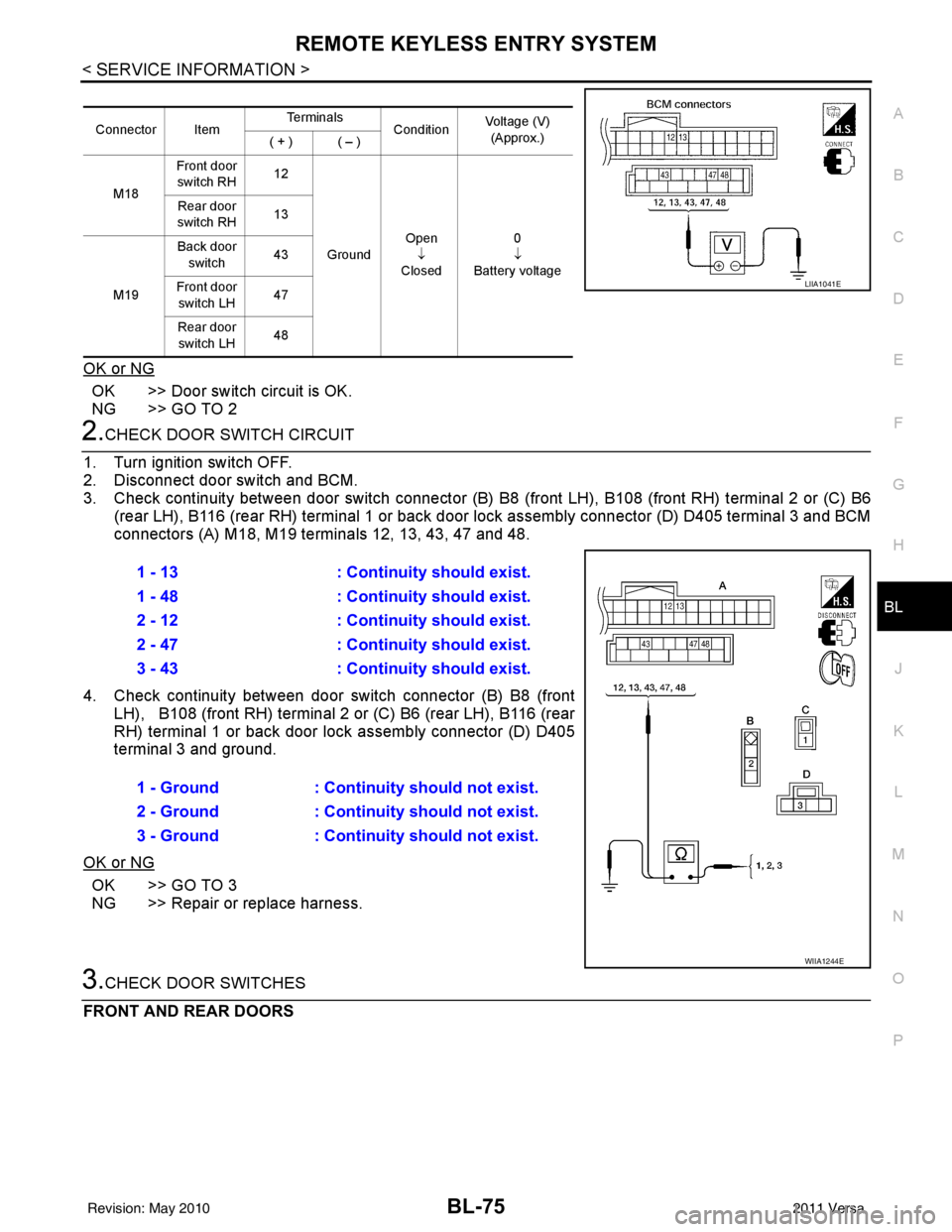
2.CHECK DOOR SWITCH CIRCUIT
1. Turn ignition switch OFF.
2. Disconnect door switch and BCM.
3. Check continuity between door switch connector (B) B8 (front LH), B108 (front RH) terminal 2 or (C) B6
(rear LH), B116 (rear RH) terminal 1 or back door lock assembly connector (D) D405 terminal 3 and BCM
connectors (A) M18, M19 te rminals 12, 13, 43, 47 and 48.
4. Check continuity between door switch connector (B) B8 (front LH), B108 (front RH) terminal 2 or (C) B6 (rear LH), B116 (rear
RH) terminal 1 or back door lo ck assembly connector (D) D405
terminal 3 and ground.
OK or NG
OK >> GO TO 3
NG >> Repair or replace harness.
3.CHECK DOOR SWITCHES
FRONT AND REAR DOORS
Connector Item Te r m i n a l s
ConditionVoltage (V)
(Approx.)
( + ) ( – )
M18 Front door
switch RH 12
Ground Open
↓
Closed 0
↓
Battery voltage
Rear door
switch RH 13
M19 Back door
switch 43
Front door switch LH 47
Rear door switch LH 48
LIIA1041E
1 - 13
: Continuity should exist.
1 - 48 : Continuity should exist.
2 - 12 : Continuity should exist.
2 - 47 : Continuity should exist.
3 - 43 : Continuity should exist.
1 - Ground : Continuity should not exist.
2 - Ground : Continuity should not exist.
3 - Ground : Continuity should not exist.
WIIA1244E
Revision: May 2010 2011 Versa
Page 586 of 3787
BL-76
< SERVICE INFORMATION >
REMOTE KEYLESS ENTRY SYSTEM
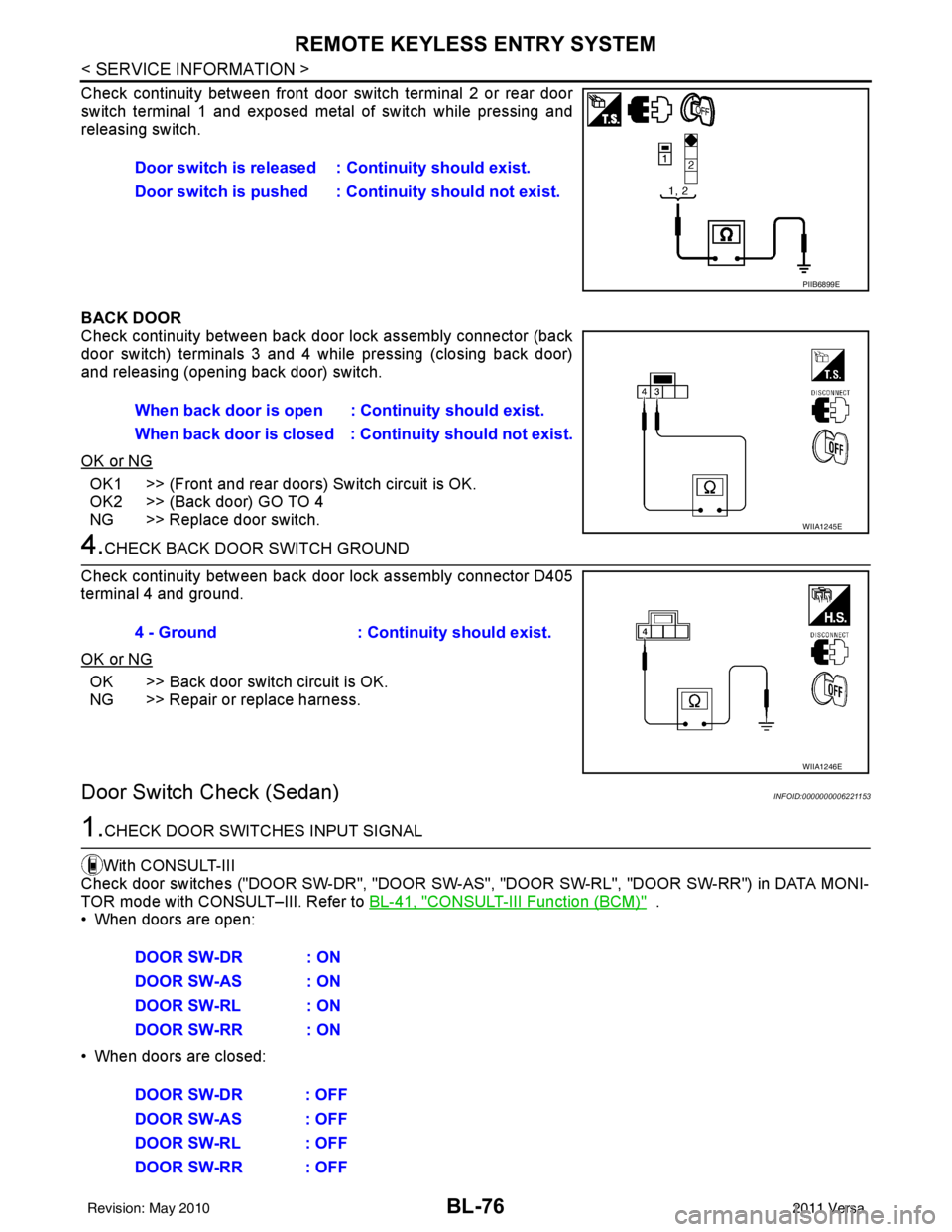
Check continuity between front door switch terminal 2 or rear door
switch terminal 1 and exposed metal of switch while pressing and
releasing switch.
BACK DOOR
Check continuity between back door lock assembly connector (back
door switch) terminals 3 and 4 while pressing (closing back door)
and releasing (opening back door) switch.
OK or NG
OK1 >> (Front and rear doors) Switch circuit is OK.
OK2 >> (Back door) GO TO 4
NG >> Replace door switch.
4.CHECK BACK DOOR SWITCH GROUND
Check continuity between back door lock assembly connector D405
terminal 4 and ground.
OK or NG
OK >> Back door switch circuit is OK.
NG >> Repair or replace harness.
Door Switch Check (Sedan)INFOID:0000000006221153
1.CHECK DOOR SWITCHES INPUT SIGNAL
With CONSULT-III
Check door switches ("DOOR SW-DR", "DOOR SW-AS" , "DOOR SW-RL", "DOOR SW-RR") in DATA MONI-
TOR mode with CONSULT–III. Refer to BL-41, "
CONSULT-III Function (BCM)" .
• When doors are open:
• When doors are closed: Door switch is released :
Continuity should exist.
Door switch is pushed : Co ntinuity should not exist.
PIIB6899E
When back door is open : Continuity should exist.
When back door is closed : Co ntinuity should not exist.
WIIA1245E
4 - Ground: Continuity should exist.
WIIA1246E
DOOR SW-DR : ON
DOOR SW-AS : ON
DOOR SW-RL : ON
DOOR SW-RR : ON
DOOR SW-DR : OFF
DOOR SW-AS : OFF
DOOR SW-RL : OFF
DOOR SW-RR : OFF
Revision: May 2010 2011 Versa
Page 598 of 3787
BL-88
< SERVICE INFORMATION >
INTELLIGENT KEY SYSTEM
System Description
INFOID:0000000005929328
• The Intelligent Key system is a system that makes it possible to lock and unlock the door locks (door lock/
unlock function), and start the engine (engine start func tion) by carrying around the Intelligent Key (without
some key operation), which operates based on the results of electronic ID verification using two-way com-
munications between the Intelligent Key and the vehicle (Intelligent Key unit).
• Vehicles equipped with a manual transmission include a key interlock solenoid located in the steering col- umn to prevent accidental shut-off of the ignition sw itch and locking of the steering wheel during driving con-
dition when the vehicle is moving.
CAUTION:
The driver should always carry the Intelligent Key
• Operation of the remote controller buttons on the Inte lligent Key also provides the same functions as the
remote control entry system. (Remote keyless entry functions)
• If an action that does not meet the operating conditions of the Intelligent Key system is taken, the buzzer
goes off to inform the driver. (Warning chime functions)
• When a door lock is locked or unlocked with request switch or remote controller button operation, the hazard
lamps flash and the buzzer (outside vehicle) sounds (Hazard and buzzer reminder function).
• Even if the Intelligent Key battery is completely discharged, the door locks can be locked and unlocked and the engine started with the mechanical key built into the Intelligent Key.
• The settings for each function can be changed with the CONSULT-III.
• If an Intelligent Key is lost, a new Intelligent Key can be registered. A maximum of 4 Intelligent Keys can be registered.
• It has been made possible to diagnose the system and r egister an Intelligent Key with the CONSULT-III.
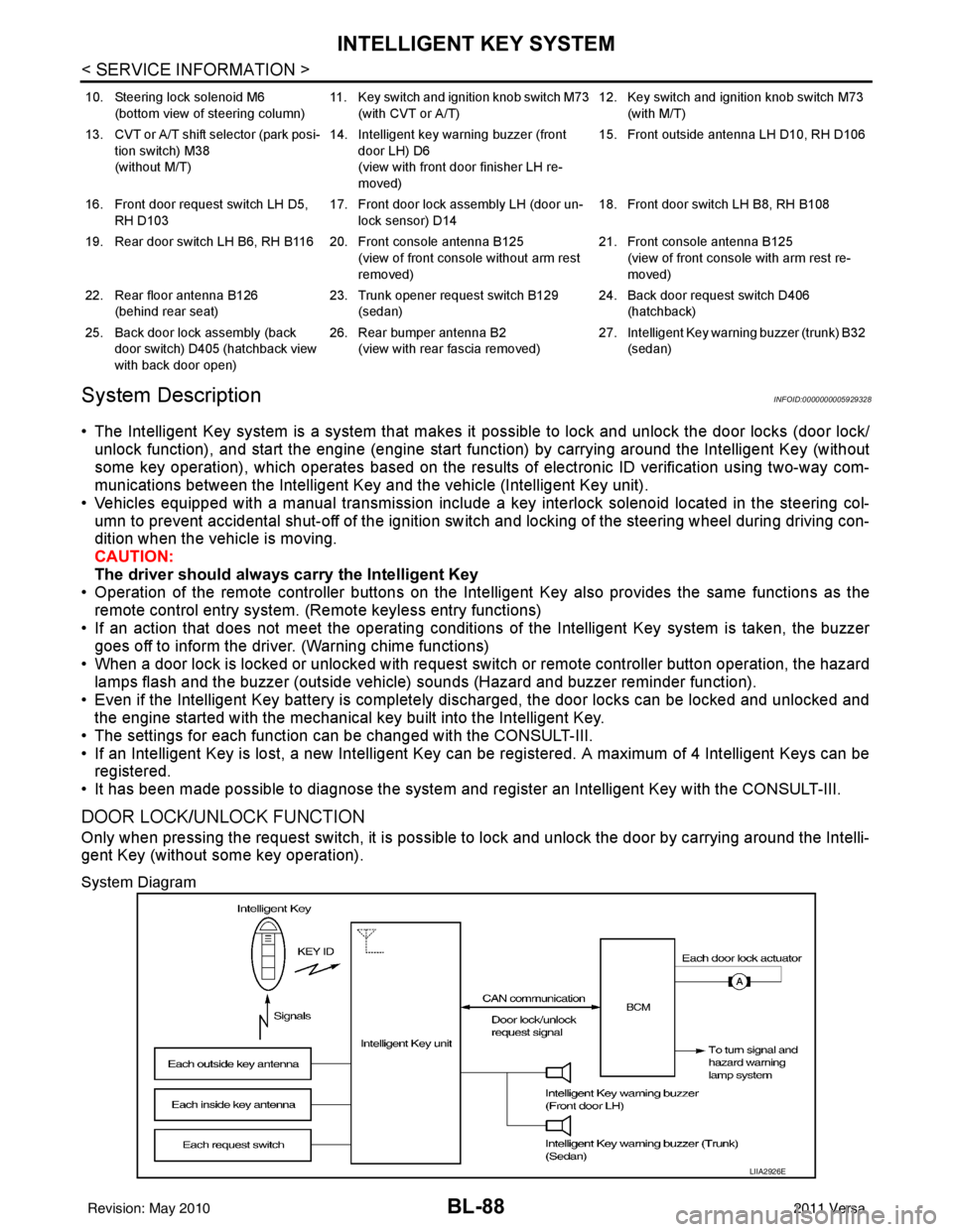
DOOR LOCK/UNLOCK FUNCTION
Only when pressing the request switch, it is possible to lock and unlock the door by carrying around the Intelli-
gent Key (without some key operation).
System Diagram
10. Steering lock solenoid M6
(bottom view of steering column) 11. Key switch and ignition knob switch M73
(with CVT or A/T) 12. Key switch and ignition knob switch M73
(with M/T)
13. CVT or A/T shift selector (park posi- tion switch) M38
(without M/T) 14. Intelligent key warning buzzer (front
door LH) D6
(view with front door finisher LH re-
moved) 15. Front outside antenna LH D10, RH D106
16. Front door request switch LH D5, RH D103 17. Front door lock assembly LH (door un-
lock sensor) D14 18. Front door switch LH B8, RH B108
19. Rear door switch LH B6, RH B116 20. Front console antenna B125 (view of front console without arm rest
removed)21. Front console antenna B125
(view of front console with arm rest re-
moved)
22. Rear floor antenna B126 (behind rear seat) 23. Trunk opener request switch B129
(sedan) 24. Back door request switch D406
(hatchback)
25. Back door lock assembly (back door switch) D405 (hatchback view
with back door open) 26. Rear bumper antenna B2
(view with rear fascia removed) 27. Intelligent Key warn
ing buzzer (trunk) B32
(sedan)
LIIA2926E
Revision: May 2010 2011 Versa
Page 599 of 3787

INTELLIGENT KEY SYSTEMBL-89
< SERVICE INFORMATION >
C
DE
F
G H
J
K L
M A
B
BL
N
O P
Operation Description
• When the Intelligent Key unit detects that each request sw
itch is pressed, it starts the outside key antenna
and inside key antenna corresponding to the pressed request switch and sends the request signal to the
Intelligent Key. And then, make sure that the Intelligent Key is near door.
• If the Intelligent Key is within the outside key antenna detection area, it receives the request signal and sends the key ID signal to the Intelligent Key unit.
• Intelligent Key unit receives the key ID signal and compares it with the registered key ID.
• If the key ID check result is OK, the Intelligent Ke y unit sends the door lock/unlock request signal to BCM
(Body control module) via CAN communication line.
• Intelligent Key unit sends the door lock/unlock signal and sounds Intelligent Key warning buzzer (lock: 2 times, unlock: 1 time) at the same time.
• When BCM receives the door lock/unlock signal, it oper ates door lock actuator and flashes the hazard warn-
ing lamp (lock: 2 times, unlock: 1 time) at the same time as reminder.
Operation Condition
If the following conditions are not satisfied, door lock/unlock operations are not performed even if the request
switch is operated.
*: Even with a registered Intelligent Key remaining inside the vehicle, door locks can be unlocked from outside of the vehicle with a spare
Intelligent Key as long as Key IDs are different.
Outside Key Antenna Detection Area
The outside key antenna detection area of door lock/unloc k function is in the range of approximately 80 cm
(31.50 in) surrounding the request switch (driver side, passenger side and back door or trunk area).
Hazard and Buzzer Reminder
When all doors and trunk (sedan) are locked or unlocked by each request switch, Intelligent Key\
unit sends
hazard request signal to BCM via CAN communication line.
BCM flashes hazard warning lamps as a reminder and Intelligent Key unit sounds Intelligent Key warning
buzzer(s) as a reminder.
Operating function of hazard and buzzer reminder
* : Sedan only
Auto Door Lock Function
When all doors and trunk (sedan) are locked, ignition knob sw itch is OFF (when ignition switch is not pressed)
and key switch is OFF (when mechanical key is out of ignition key cylinder), all doors are unlocked with each
request switch.
When Intelligent Key unit does not receive the following signals within 1 minute, all doors are locked.
• Door switch is ON (door is opened)
• Trunk lamp switch (sedan) is ON (trunk is opened)
• Door lock signal from Intelligent Key button
• Ignition knob switch is ON (ignition switch is pressed)
• Key switch is ON (mechanical key is inserted in ignition key cylinder)
Auto door lock mode can be changed by “AUTO RELOCK TIMER” mode in “WORK SUPPORT”. Refer to BL-
117, "CONSULT-III Application Item".
List of Operation Related Parts
Parts marked with × are the parts related to operation.
Each request switch operation Operation conditionOperation
Lock operation • All doors and trunk (sedan) are closed
• Intelligent Key is outside of the vehicle
• Intelligent Key is within outside key antenna detection area All doors lock
Unlock Operation • All doors and trunk (sedan) are closed
• Intelligent Key is outside of the vehicle
• Intelligent Key is within outside key antenna detection area*
All doors unlock
Request switch operation
Hazard warning lamp flashIntelligent Key warning buzzer (front door LH)
Intelligent Key warning buzzer (trunk)*
Unlock Once Once
Lock Twice Twice
Revision: May 2010 2011 Versa