Page 3369 of 3787

TROUBLE DIAGNOSISMTC-53
< SERVICE INFORMATION >
C
DE
F
G H
I
K L
M A
B
MTC
N
O P
Insufficient HeatingINFOID:0000000005930855
SYMPTOM: Insufficient heating
INSPECTION FLOW
1.CONFIRM SYMPTOM BY PERFORMING OPERAT IONAL CHECK - TEMPERATURE INCREASE
1. Turn temperature control dial clockwise to maximum heat position.
2. Check for hot air at discharge air outlets.
Can the symptom be duplicated?
YES >> GO TO 3.
NO >> GO TO 2.
2.CHECK FOR ANY SYMPTOMS
Perform a complete operational check for any symptoms. Refer to MTC-31, "
Operational Check" .
Does another symptom exist?
YES >> Refer to MTC-23, "How to Perform Trouble Diagnosis for Quick and Accurate Repair" .
NO >> System OK.
3.CHECK FOR SERVICE BULLETINS
Check for any service bulletins.
>> GO TO 4.
4.CHECK COOLANT SYSTEM
1. Check engine coolant level. Refer to CO-11, "
Inspection" (HR16DE) or CO-36, "Inspection" (MR18DE).
2. Check hoses for leaks or kinks.
3. Check Radiator cap. Refer to CO-14, "
Checking Radiator Cap" HR16DE or CO-39, "Checking Radiator
Cap" (MR18DE).
OK or NG
OK >> GO TO 5.
NG >> Repair/replace as necessary.
5.CHECK AIR MIX DOOR CABLE
Check air mix door cable operation. Refer to MTC-65, "
Air Mix Door Cable Adjustment" .
OK or NG
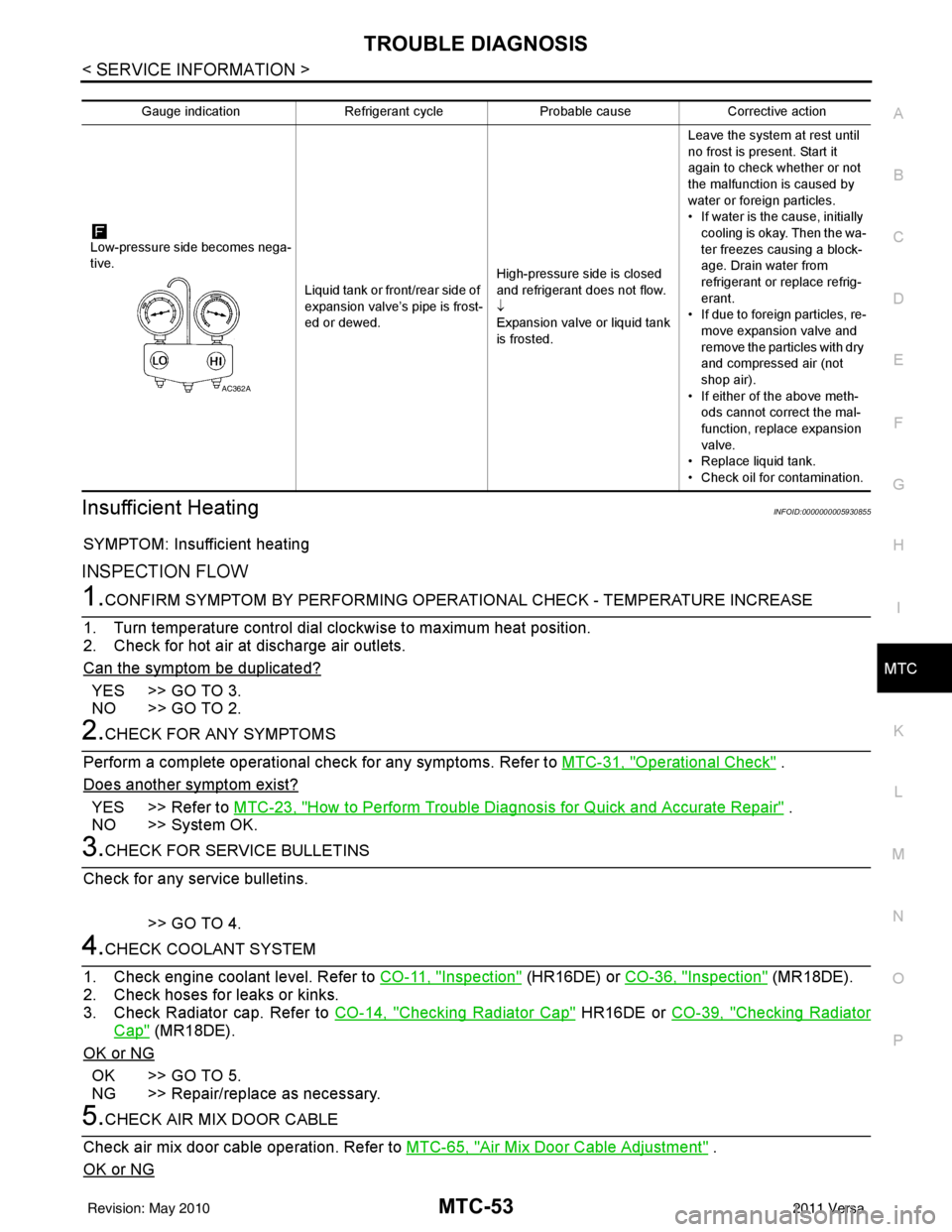
Gauge indication Refrigerant cycleProbable causeCorrective action
Low-pressure side becomes nega-
tive. Liquid tank or front/rear side of
expansion valve’s pipe is frost-
ed or dewed.High-pressure side is closed
and refrigerant does not flow.
↓
Expansion valve or liquid tank
is frosted.Leave the system at rest until
no frost is present. Start it
again to check whether or not
the malfunction is caused by
water or foreign particles.
• If water is the cause, initially
cooling is okay. Then the wa-
ter freezes causing a block-
age. Drain water from
refrigerant or replace refrig-
erant.
• If due to foreign particles, re-
move expansion valve and
remove the particles with dry
and compressed air (not
shop air).
• If either of the above meth- ods cannot correct the mal-
function, replace expansion
valve.
• Replace liquid tank.
• Check oil for contamination.
AC362A
Revision: May 2010 2011 Versa
Page 3370 of 3787

MTC-54
< SERVICE INFORMATION >
TROUBLE DIAGNOSIS
YES >> GO TO 6.
NO >> Adjust or replace air mix door cable. Refer to MTC-65, "
Air Mix Door Cable Adjustment" .
6.CHECK AIR DUCTS
Check ducts for air leaks.
OK or NG
OK >> GO TO 7.
NG >> Repair air leaks.
7.CHECK HEATER HOSE TEMPERATURES
1. Start engine and warm it up to normal operating temperature.
2. Touch both the inlet and outlet heater hoses. The inlet hose should be hot and the outlet hose should be
warm.
Is the inlet hose hot and the outlet hose warm?
YES >> GO TO 8.
NO >> Both hoses warm: GO TO 9.
8.CHECK ENGINE COOLANT TEMPERATURE SENSOR
Check engine control temperature sensor. Refer to EC-172, "
Component Inspection" (MR18DE) or EC-690,
"Component Inspection" (HR16DE).
OK or NG
OK >> System OK.
NG >> Repair or replace as necessary. Retest.
9.CHECK HEATER HOSES
Check heater hoses for proper installation.
OK or NG
OK >> GO TO 10.
NG >> Repair /replace as necessary. Retest GO TO 7.
10.BACK FLUSH HEATER CORE
1. Back flush heater core.
2. Drain the water from the system.
3. Refill system with new engine coolant. Refer to CO-11, "
Changing Engine Coolant" (HR16DE) or CO-36,
"Changing Engine Coolant" (MR18DE) .
4. Start engine and warm it up to normal operating temperature.
5. Touch both the inlet and outlet heater hoses. The inlet hose should be hot and the outlet hose should be
warm.
Is the inlet hose hot and the outlet hose warm?
YES >> System OK.
NO >> Replace heater core and refill engine coolant. Refer to MTC-68, "
Removal and Installation" .
NoiseINFOID:0000000005930856
SYMPTOM: Noise
INSPECTION FLOW
Revision: May 2010 2011 Versa
Page 3466 of 3787

PG-46
< SERVICE INFORMATION >
HARNESS
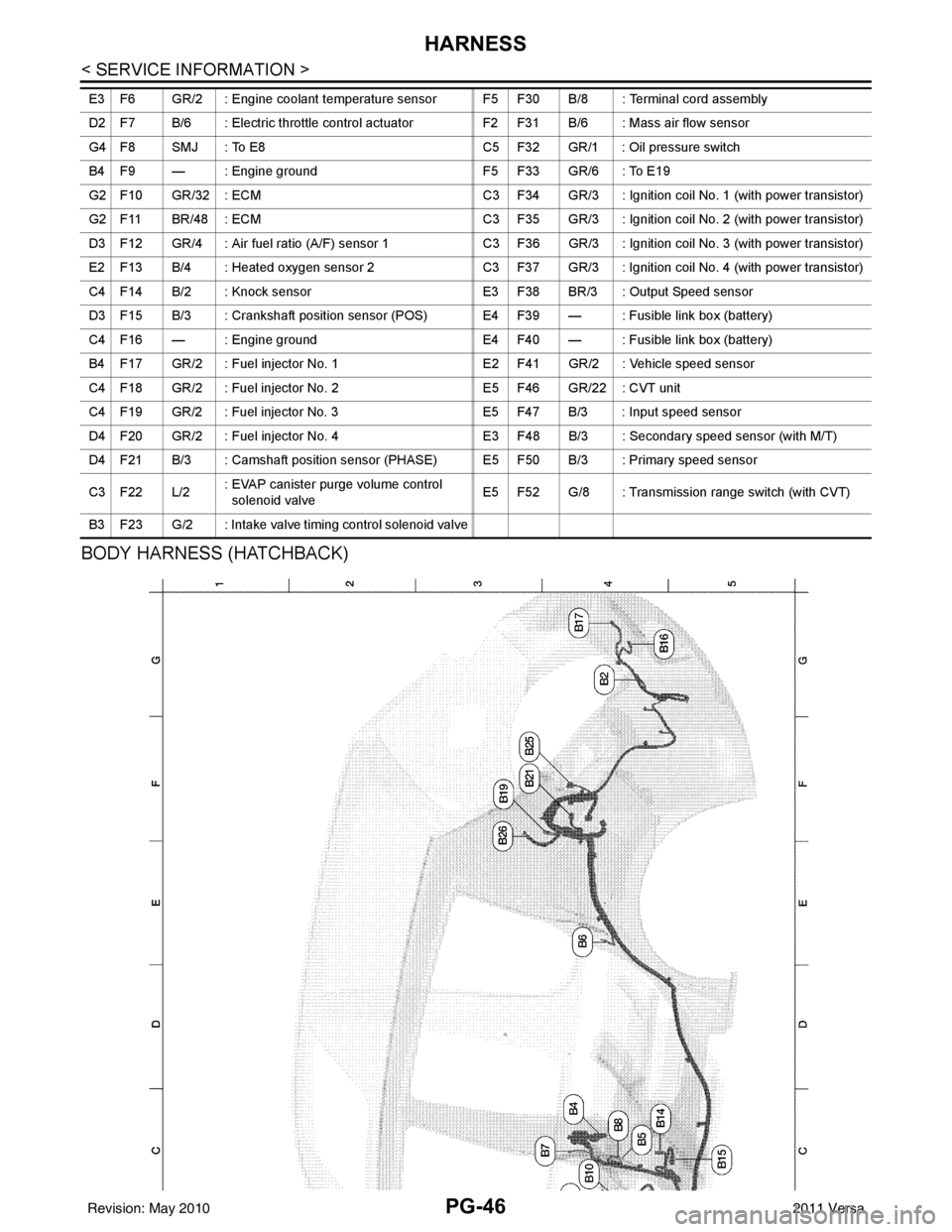
BODY HARNESS (HATCHBACK)
E3 F6 GR/2 : Engine coolant temperature sensor F5 F30 B/8 : Terminal cord assembly
D2 F7 B/6 : Electric throttle control actuatorF2 F31 B/6 : Mass air flow sensor
G4 F8 SMJ : To E8 C5 F32 GR/1 : Oil pressure switch
B4 F9 — : Engine ground F5 F33 GR/6 : To E19
G2 F10 GR/32 : ECM C3 F34 GR/3 : Ignition coil No. 1 (with power transistor)
G2 F11 BR/48 : ECM C3 F35 GR/3 : Ignition coil No. 2 (with power transistor)
D3 F12 GR/4 : Air fuel ratio (A/F) sensor 1 C3 F36 GR/3 : Ignition coil No. 3 (with power transistor)
E2 F13 B/4 : Heated oxygen sensor 2 C3 F37 GR/3 : Ignition coil No. 4 (with power transistor)
C4 F14 B/2 : Knock sensor E3 F38 BR/3 : Output Speed sensor
D3 F15 B/3 : Crankshaft position sensor (POS) E4 F39 — : Fusible link box (battery)
C4 F16 — : Engine ground E4 F40 — : Fusible link box (battery)
B4 F17 GR/2 : Fuel injector No. 1 E2 F41 GR/2 : Vehicle speed sensor
C4 F18 GR/2 : Fuel injector No. 2E5 F46 GR/22 : CVT unit
C4 F19 GR/2 : Fuel injector No. 3 E5 F47 B/3 : Input speed sensor
D4 F20 GR/2 : Fuel injector No. 4 E3 F48 B/3 : Secondary speed sensor (with M/T)
D4 F21 B/3 : Camshaft position sensor (PHASE) E5 F50 B/3 : Primary speed sensor
C3 F22 L/2 : EVAP canister purge volume control
solenoid valve E5 F52 G/8 : Transmission range switch (with CVT)
B3 F23 G/2 : Intake valve timing control solenoid valve
Revision: May 2010 2011 Versa
Page 3478 of 3787

PG-58
< SERVICE INFORMATION >
HARNESS
Wiring Diagram Codes (Cell Codes)
INFOID:0000000005928356
Use the chart below to find out what each wiring diagram code stands for.
Refer to the wiring diagram code in the alphabetical index to find the location (page number) of each wiring
diagram.
D4 D406 W/2 : Back door request switch C2 D413 B/1 : Rear window defogger (-)
E2 D407 W/2 : High mounted stop lamp
Code Section Wiring Diagram Name
ABS BRC Anti-lock Brake System
A/C,M MTC Manual Air Conditioner
APPS1 EC Accelerator Pedal Position Sensor
A/F EC Air Fuel Ratio Sensor 1
A/FH EC Air Fuel Ratio Sensor 1 Heater
APPS2 EC Accelerator Pedal Position Sensor
APPS3 EC Accelerator Pedal Position Sensor
ASC/BS EC ASCD Brake Switch
ASC/SW EC ASCD Steering Switch
ASCBOF EC ASCD Brake Switch
ASCIND EC ASCD Indicator
AT/IND DI A/T Indicator Lamp
AUDIO AV Audio
BACK/L LT Back-up Lamp
BA/FTS AT A/T Fluid Temperature Sensor and TCM Power Supply
B/DOOR BL Back Door Opener
BRK/SW EC Brake Switch
CAN AT CAN Communication Line
CAN CVT CAN Communication Line
CAN EC CAN Communication Line
CAN LAN CAN System
CHARGE SC Charging System
CHIME DI Warning Chime
COOL/F EC Cooling Fan Control
COMBSW LT Combination Switch
COMM AV Audio Visual Communication System
CVTIND DI CVT Indicator Lamp
D/LOCK BL Power Door Lock
DEF GW Rear Window Defogger
DTRL LT Headlamp - With Daytime Light System
ECTS EC Engine Coolant Temperature Sensor
ENGSS AT Engine Speed Signal
EPS STC Electronic Controlled Power Steering
ETC1 EC Electric Throttle Control Function
ETC2 EC Throttle Control Motor Relay
ETC3 EC Throttle Control Motor
F/FOG LT Front Fog Lamp
F/PUMP EC Fuel Pump
FTS AT A/T Fluid Temperature Sensor
FTS CVT CVT Fluid Temperature Sensor Circuit
FTTS EC Fuel Tank Temperature Sensor
FUEL EC Fuel Ignition System Function
HEATER MTC Heater System
Revision: May 2010 2011 Versa
Page 3597 of 3787

STARTING SYSTEMSC-19
< SERVICE INFORMATION >
C
DE
F
G H
I
J
L
M A
B
SC
N
O P
• 10A fuse (No. 49, M/T model s, located in the IPDM E/R)
• 15A fuse (No. 52, located in the IPDM E/R)
• 20A fuse (No. 53, located in the IPDM E/R)
• Transmission range switch, clutch interlock switch or TCM depending on equipment
• Ignition switch
• Ignition relay IPDM E/R
• Starter relay IPDM E/R
• Starter relay request ON signal from BCM
• Harness for open or short circuit
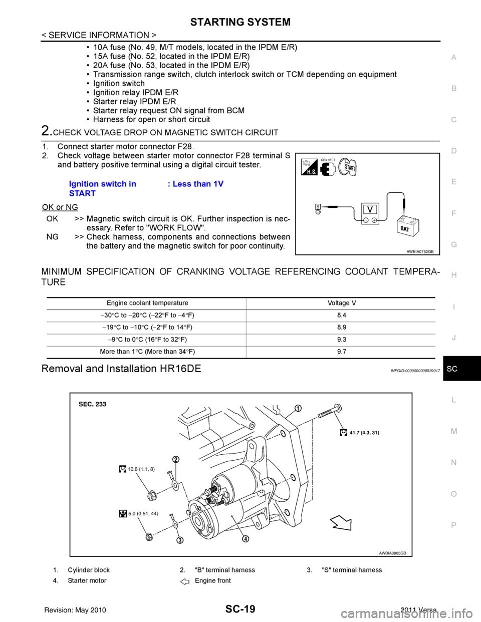
2.CHECK VOLTAGE DROP ON MAGNETIC SWITCH CIRCUIT
1. Connect starter motor connector F28.
2. Check voltage between starter motor connector F28 terminal S and battery positive terminal using a digital circuit tester.
OK or NG
OK >> Magnetic switch circuit is OK. Further inspection is nec-
essary. Refer to "WORK FLOW".
NG >> Check harness, components and connections between the battery and the magnetic switch for poor continuity.
MINIMUM SPECIFICATION OF CRANKING VO LTAGE REFERENCING COOLANT TEMPERA-
TURE
Removal and Installation HR16DEINFOID:0000000005929017
Ignition switch in
START : Less than 1V
AWBIA0752GB
Engine coolant temperature
Voltage V
− 30 °C to − 20°C ( −22 °F to −4 °F) 8.4
− 19 °C to − 10°C ( −2°F to 14 °F) 8.9
− 9 °C to 0 °C (16 °F to 32 °F) 9.3
More than 1 °C (More than 34 °F) 9.7
1. Cylinder block2. "B" terminal harness3. "S" terminal harness
4. Starter motor Engine front
AWBIA0885GB
Revision: May 2010 2011 Versa