2011 NISSAN TIIDA coolant temperature
[x] Cancel search: coolant temperaturePage 2214 of 3787
![NISSAN TIIDA 2011 Service Repair Manual EC-920
< SERVICE INFORMATION >[MR18DE]
DTC P1217 ENGINE OVER TEMPERATURE
*1: Turn the ignition switch ON.
*2: Engine running at 3,000 rpm for 10 minutes.
*3: Drive at 90 km/h (55 MPH) for 30 minutes a NISSAN TIIDA 2011 Service Repair Manual EC-920
< SERVICE INFORMATION >[MR18DE]
DTC P1217 ENGINE OVER TEMPERATURE
*1: Turn the ignition switch ON.
*2: Engine running at 3,000 rpm for 10 minutes.
*3: Drive at 90 km/h (55 MPH) for 30 minutes a](/manual-img/5/57396/w960_57396-2213.png)
EC-920
< SERVICE INFORMATION >[MR18DE]
DTC P1217 ENGINE OVER TEMPERATURE
*1: Turn the ignition switch ON.
*2: Engine running at 3,000 rpm for 10 minutes.
*3: Drive at 90 km/h (55 MPH) for 30 minutes and then let idle for 10 minutes.
*4: After 60 minutes of cool down time.
For more informat
ion, refer to CO-32
.
Component InspectionINFOID:0000000006342107
COOLING FAN MOTOR
Model with A/C
1. Disconnect cooling fan motor harness connectors.
2. Supply cooling fan motor terminals with battery voltage and
check operation.
Cooling fan motor should operate.
If NG, replace cooling fan motor.
Models without A/C
1. Disconnect cooling fan motor harness connectors.
2. Supply cooling fan motor terminals with battery voltage and check operation.
Cooling fan motor should operate.
If NG, replace cooling fan motor.
OFF*410 •Coolant retu
rn from res-
ervoir tank to radiator •Visual Should be initial level in
reservoir tank See
CO-36.
OFF 11 • Water control valve • Remove and inspect
the valve Within the specified value See
CO-47
OFF12 • Cylinder head
• Straight gauge feeler
gauge 0.1 mm (0.004 in) Maxi-
mum distortion (warping)
See
EM-186
.
13 • Cylinder block and pis-
tons •Visual No scuffing on cylinder
walls or piston See
EM-202
.
Engine Step Inspection item
EquipmentStandardReference
Cooling fan motor Te r m i n a l s
(+) (-) 12
SEF888V
Cooling fan motor Speed
terminals
(+) (− )
Low 14
23
High 1 and 2 3 and 4
SEF734W
Revision: May 2010 2011 Versa
Page 2329 of 3787
![NISSAN TIIDA 2011 Service Repair Manual SERVICE DATA AND SPECIFICATIONS (SDS)EC-1035
< SERVICE INFORMATION > [MR18DE]
C
D
E
F
G H
I
J
K L
M A
EC
NP
O
SERVICE DATA AND SPECIFICATIONS (SDS)
Fuel PressureINFOID:0000000006342252
Idle Speed and NISSAN TIIDA 2011 Service Repair Manual SERVICE DATA AND SPECIFICATIONS (SDS)EC-1035
< SERVICE INFORMATION > [MR18DE]
C
D
E
F
G H
I
J
K L
M A
EC
NP
O
SERVICE DATA AND SPECIFICATIONS (SDS)
Fuel PressureINFOID:0000000006342252
Idle Speed and](/manual-img/5/57396/w960_57396-2328.png)
SERVICE DATA AND SPECIFICATIONS (SDS)EC-1035
< SERVICE INFORMATION > [MR18DE]
C
D
E
F
G H
I
J
K L
M A
EC
NP
O
SERVICE DATA AND SPECIFICATIONS (SDS)
Fuel PressureINFOID:0000000006342252
Idle Speed and Ignition TimingINFOID:0000000006342253
*: Under the following conditions:
• Air conditioner switch: OFF
• Electric load: OFF (Lights, heater fan & rear window defogger)
• Steering wheel: Kept in straight-ahead position
Calculated Load ValueINFOID:0000000006342254
Mass Air Flow SensorINFOID:0000000006342255
*: Engine is warmed up to normal operating temperature and running under no load.
Intake Air Temperature SensorINFOID:0000000006342256
Engine Coolant Temperature SensorINFOID:0000000006342257
Fuel pressure at idle
Approximately 350 kPa (3.57 kg/cm2, 51 psi)
Target idle speedA/T No load* (in P or N position)
700 ± 50 rpm
CVT No load* (In P or N position)
M/T No load* (in Neutral position)
Air conditioner: ON A/T In P or N position
850 rpm or more
CVT In P or N position
M/T In Neutral position
Ignition timing A/T In P or N position
13 ± 5 ° BTDC
CVT In P or N position
M/T In Neutral position
Calculated load value (Using CONSULT-III or GST)
At idle 10 - 35 %
At 2,500 rpm 10 - 35 %
Supply voltageBattery voltage (11 - 14 V )
Output voltage at idle 1.0 - 1.3* V
Mass air flow (Using CONSULT-III or GST) 1.0 - 4.0 g·m/sec at idle*
2.0 - 10.0 g·m/sec at 2,500 rpm*
Temperature [ °C ( °F)] Resistance (k Ω)
25 (77) 1.800 - 2.200
Temperature [°C ( °F)] Resistance (k Ω)
20 (68) 2.1 - 2.9
50 (122) 0.68 - 1.00
90 (194) 0.236 - 0.260
Revision: May 2010 2011 Versa
Page 2751 of 3787

TERMINOLOGYGI-47
< SERVICE INFORMATION >
C
DE
F
G H
I
J
K L
M B
GI
N
O PTERMINOLOGY
SAE J1930 Terminology ListINFOID:0000000005929743
All emission related terms used in this publication in accordance with SAE J1930 are listed. Accordingly, new
terms, new acronyms/abbreviations and old terms are listed in the following chart.
NEW TERM NEW ACRONYM /
ABBREVIATION OLD TERM
Air cleaner ACL Air cleaner
Barometric pressure BARO ***
Barometric pressure sensor-BCDD BAROS-BCDD BCDD
Camshaft position CMP***
Camshaft position sensor CMPSCrank angle sensor
Canister ***Canister
Carburetor CARB Carburetor
Charge air cooler CACIntercooler
Closed loop CLClosed loop
Closed throttle position switch CTP switchIdle switch
Clutch pedal position switch CPP switchClutch switch
Continuous fuel injection system CFI system ***
Continuous trap oxidizer system CTOX system***
Crankshaft position CKP ***
Crankshaft position sensor CKPS ***
Data link connector DLC***
Data link connector fo r CONSULT-III DLC for CONSULT-III Diagnostic connector for CONSULT-III
Diagnostic test mode DTMDiagnostic mode
Diagnostic test mode selector DTM selectorDiagnostic mode selector
Diagnostic test mode I DTM IMode I
Diagnostic test mode II DTM IIMode II
Diagnostic trouble code DTCMalfunction code
Direct fuel injection system DFI system ***
Distributor ignition system DI system Ignition timing control
Early fuel evaporation-mixture heater EFE-mixture heater Mixture heater
Early fuel evaporation system EFE systemMixture heater control
Electrically erasable programmable read
only memory EEPROM
***
Electronic ignition system EI systemIgnition timing control
Engine control EC ***
Engine control module ECMECCS control unit
Engine coolant temperature ECTEngine temperature
Engine coolant temperature sensor ECTS Engine temperature sensor
Engine modification EM ***
Engine speed RPMEngine speed
Erasable programmable read only memory EPROM ***
Evaporative emission canister EVAP canisterCanister
Evaporative emission system EVAP systemCanister control solenoid valve
Exhaust gas recirculation valve EGR valve EGR valve
Revision: May 2010 2011 Versa
Page 2873 of 3787
![NISSAN TIIDA 2011 Service Repair Manual CAN COMMUNICATION SYSTEMLAN-27
< SERVICE INFORMATION > [CAN]
C
D
E
F
G H
I
J
L
M A
B
LAN
N
O P
CAN Communication Signal ChartINFOID:0000000005928534
Refer to LAN-16, "How to Use CAN Communication Sig NISSAN TIIDA 2011 Service Repair Manual CAN COMMUNICATION SYSTEMLAN-27
< SERVICE INFORMATION > [CAN]
C
D
E
F
G H
I
J
L
M A
B
LAN
N
O P
CAN Communication Signal ChartINFOID:0000000005928534
Refer to LAN-16, "How to Use CAN Communication Sig](/manual-img/5/57396/w960_57396-2872.png)
CAN COMMUNICATION SYSTEMLAN-27
< SERVICE INFORMATION > [CAN]
C
D
E
F
G H
I
J
L
M A
B
LAN
N
O P
CAN Communication Signal ChartINFOID:0000000005928534
Refer to LAN-16, "How to Use CAN Communication Signal Chart" for how to use CAN communication signal
chart.
NOTE:
Refer to LAN-22, "
Abbreviation List" for the abbreviations of the connecting units.
T: Transmit R: Receive
Signal name/Connecting unitECM
BCM
EPS
I-KEY M&A
STRG ABS
TCM
*1
TCM
*2
IPDM-E
A/C compressor request signal T R
Accelerator pedal position signal T
R
*3RR
ASCD CRUISE lamp signal T R
ASCD SET lamp signal T R
Closed throttle position signal T R R
Cooling fan motor operation signal T R
Engine coolant temperature signal TR
Engine speed signal TR
R
*3R
Engine status signal T R R R
Fuel consumption monitor signal T R
Malfunction indicator lamp signal TR
Wide open throttle position signal T R R
A/C switch signal R T
Blower fan motor switch signal R T
Buzzer output signal TR
TR
Day time running light request signal
*4TR
Door lock/unlock status signal TR
Door switch signal TR R R
Front wiper request signal T R
High beam request signal TR R
Horn chirp signal T R
Ignition switch signal T R
Low beam request signal T R
Position lights request signal TR R
Rear window defogger switch signal T R
Sleep/wake up signal TRR
R
RT
Theft warning horn request signal T R
Tire pressure signal
*5TR
Trunk open/close status signal TR
Turn indicator signal TR
EPS operation signal TR
EPS warning lamp signal TR
Door lock/unlock/trunk open request signal RT
Hazard request signal RT
Ignition knob switch signal RT
Revision: May 2010 2011 Versa
Page 3179 of 3787

MA-8
< SERVICE INFORMATION >
GENERAL MAINTENANCE
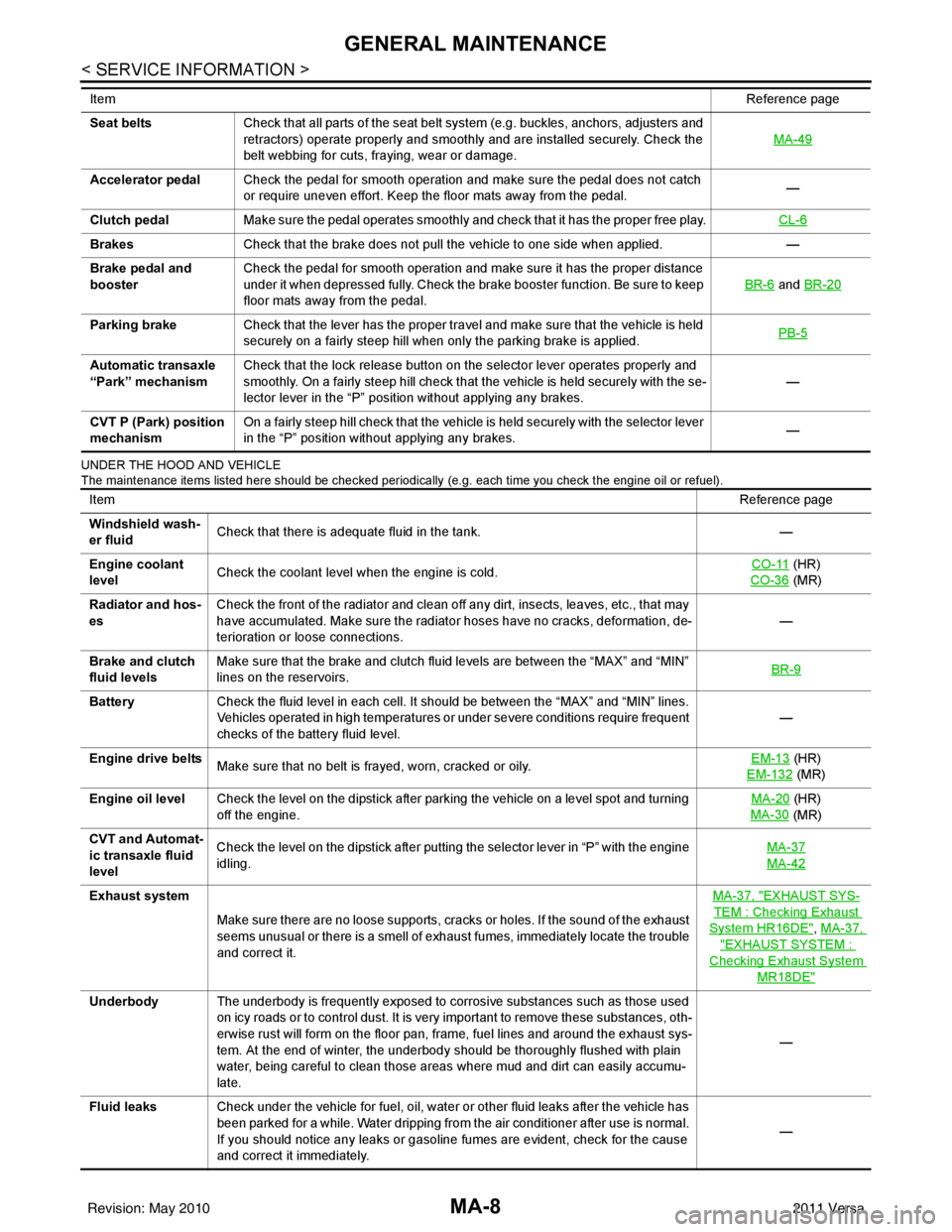
UNDER THE HOOD AND VEHICLE
The maintenance items listed here should be checked periodically (e.g. each time you check the engine oil or refuel).
Seat beltsCheck that all parts of the seat belt system (e.g. buckles, anchors, adjusters and
retractors) operate properly and smoothly and are installed securely. Check the
belt webbing for cuts, fraying, wear or damage. MA-49
Accelerator pedal
Check the pedal for smooth operation and make sure the pedal does not catch
or require uneven effort. Keep the floor mats away from the pedal. —
Clutch pedal Make sure the pedal operates smoothly and check that it has the proper free play. CL-6
BrakesCheck that the brake does not pull the vehicle to one side when applied. —
Brake pedal and
booster Check the pedal for smooth operation and make sure it has the proper distance
under it when depressed fully. Check the brake booster function. Be sure to keep
floor mats away from the pedal. BR-6
and
BR-20
Parking brake Check that the lever has the proper travel and make sure that the vehicle is held
securely on a fairly steep hill when only the parking brake is applied. PB-5
Automatic transaxle
“Park” mechanismCheck that the lock release button on the selector lever operates properly and
smoothly. On a fairly steep hill check that the vehicle is held securely with the se-
lector lever in the “P” position without applying any brakes. —
CVT P (Park) position
mechanism On a fairly steep hill check that the vehicle is held securely with the selector lever
in the “P” position without applying any brakes.
—
Item
Reference page
ItemReference page
Windshield wash-
er fluid Check that there is adequate fluid in the tank.
—
Engine coolant
level Check the coolant level when the engine is cold. CO-11
(HR)
CO-36
(MR)
Radiator and hos-
es Check the front of the radiator and clean off any dirt, insects, leaves, etc., that may
have accumulated. Make sure the radiator hoses have no cracks, deformation, de-
terioration or loose connections.
—
Brake and clutch
fluid levels Make sure that the brake and clutch fluid levels are between the “MAX” and “MIN”
lines on the reservoirs.
BR-9
Battery
Check the fluid level in each cell. It should be between the “MAX” and “MIN” lines.
Vehicles operated in high temperatures or under severe conditions require frequent
checks of the battery fluid level. —
Engine drive belts Make sure that no belt is frayed, worn, cracked or oily. EM-13
(HR)
EM-132
(MR)
Engine oil level Check the level on the dipstick after parking the vehicle on a level spot and turning
off the engine. MA-20
(HR)
MA-30
(MR)
CVT and Automat-
ic transaxle fluid
level Check the level on the dipstick after putting the selector lever in “P” with the engine
idling.
MA-37
MA-42
Exhaust system
Make sure there are no loose supports, cracks or holes. If the sound of the exhaust
seems unusual or there is a smell of exhaust fumes, immediately locate the trouble
and correct it. MA-37, "EXHAUST SYS-
TEM : Checking Exhaust
System HR16DE", MA-37,
"EXHAUST SYSTEM :
Checking Exhaust System
MR18DE"
Underbody
The underbody is frequently exposed to corrosive substances such as those used
on icy roads or to control dust. It is very important to remove these substances, oth-
erwise rust will form on the floor pan, frame, fuel lines and around the exhaust sys-
tem. At the end of winter, the underbody should be thoroughly flushed with plain
water, being careful to clean those areas where mud and dirt can easily accumu-
late. —
Fluid leaks Check under the vehicle for fuel, oil, water or other fluid leaks after the vehicle has
been parked for a while. Water dripping from the air conditioner after use is normal.
If you should notice any leaks or gasoline fumes are evident, check for the cause
and correct it immediately. —
Revision: May 2010
2011 Versa
Page 3180 of 3787

PERIODIC MAINTENANCEMA-9
< SERVICE INFORMATION >
C
DE
F
G H
I
J
K
M A
B
MA
N
O P
PERIODIC MAINTENANCE
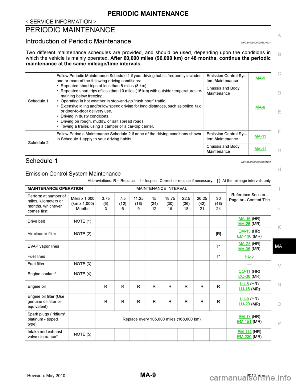
Introduction of Periodic MaintenanceINFOID:0000000005931131
Two different maintenance schedules are provi ded, and should be used, depending upon the conditions in
which the vehicle is mainly operated. After 60,000 miles (96,000 km) or 48 months, continue the periodic
maintenance at the same mileage/time intervals.
Schedule 1INFOID:0000000005931132
Emission Control System Maintenance
Abbreviations: R = Replace. I = Inspect. Correct or r eplace if necessary. [ ]: At the mileage intervals only
Schedule 1Follow Periodic Maintenance Schedule 1 if your driving habits frequently includes
one or more of the following driving conditions:
• Repeated short trips of less than 5 miles (8 km).
• Repeated short trips of less than 10 miles (16 km) with outside temperatures re-
maining below freezing.
• Operating in hot weather in stop-and-go “rush hour” traffic.
• Extensive idling and/or low speed driving for long distances, such as police, taxi
or door-to-door delivery use.
• Driving in dusty conditions.
• Driving on rough, muddy, or salt spread roads.
• Towing a trailer, using a camper or a car-top carrier. Emission Control Sys-
tem Maintenance
MA-9
Chassis and Body
Maintenance
MA-9
Schedule 2Follow Periodic Maintenance Schedule 2 if none of the driving conditions shown
in Schedule 1 apply to your driving habits.
Emission Control Sys-
tem Maintenance
MA-11Chassis and Body
Maintenance
MA-11
MAINTENANCE OPERATION
MAINTENANCE INTERVAL
Reference Section -
Page or - Content Title
Perform at number of
miles, kilometers or
months, whichever
comes first. Miles x 1,000
(km x 1,000) Months 3.75
(6)3 7.5
(12) 6 11 . 2 5
(18) 9 15
(24) 12 18.75
(30)15 22.5
(36) 18 26.25
(42)21 30
(48) 24
Drive belt NOTE (1) MA-16
(HR)
MA-26
(MR)
Air cleaner filter NOTE (2) [R]EM-13
(HR)
EM-136
(MR)
EVAP vapor lines I*MA-25
(HR)
MA-36
(MR)
Fuel lines I*FL-5
Fuel filter NOTE (3) —
Engine coolant* NOTE (4) CO-11
(HR)
CO-36
(MR)
Engine oil R R R R R R R R LU-8
(HR)
LU-18
(MR)
Engine oil filter (Use
genuine oil filter or
equivalent) RRRRRRRR
LU-9
(HR)
LU-20
(MR)
Spark plugs (Iridium/
platinum - tipped
type) Replace every 105,000 miles (168,000 km)
EM-17
(HR)
EM-151
(MR)
Intake and exhaust
valve clearance* NOTE (5) EM-114
(HR)
EM-230
(MR)
Revision: May 2010 2011 Versa
Page 3186 of 3787

RECOMMENDED FLUIDS AND LUBRICANTSMA-15
< SERVICE INFORMATION >
C
DE
F
G H
I
J
K
M A
B
MA
N
O P
SAE Viscosity NumberINFOID:0000000005931135
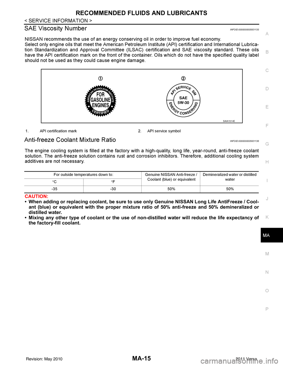
NISSAN recommends the use of an energy conser ving oil in order to improve fuel economy.
Select only engine oils that meet the American Petroleum Institute (API) certification and International Lubrica-
tion Standardization and Approval Committee (ILSAC) ce rtification and SAE viscosity standard. These oils
have the API certification mark on the front of the container. Oils which do not have the specified quality label
should not be used as they could cause engine damage.
Anti-freeze Coolant Mixture RatioINFOID:0000000005931136
The engine cooling system is filled at the factory wit h a high-quality, long life, year-round, anti-freeze coolant
solution. The anti-freeze solution contains rust and corrosion inhibitors. Therefore, additional cooling system
additives are not necessary.
CAUTION:
• When adding or replacing coolant, be sure to u se only Genuine NISSAN Long Life AntiFreeze / Cool-
ant (blue) or equivalent with the proper mixture ratio of 50% an ti-freeze and 50% demineralized or
distilled water.
• Mixing any other type of coolant or the use of non-distilled water will reduce the life expectancy of
the factory-fi ll coolant.
SAIA1514E
1. API certification mark 2. API service symbol
For outside temperatures down to :Genuine NISSAN Anti-freeze /
Coolant (blue) or equivalent Demineralized water or distilled
water
° C °F
-35 -3050% 50%
Revision: May 2010 2011 Versa
Page 3190 of 3787

ENGINE MAINTENANCE (HR16DE)MA-19
< SERVICE INFORMATION >
C
DE
F
G H
I
J
K
M A
B
MA
N
O P
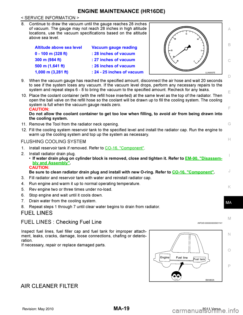
8. Continue to draw the vacuum until the gauge reaches 28 inches of vacuum. The gauge may not reach 28 inches in high altitude
locations, use the vacuum specifications based on the altitude
above sea level.
9. When the vacuum gauge has reached the specified amount, disconnect the air hose and wait 20 seconds
to see if the system loses any vacuum. If the vacuum level drops, perform any necessary repairs to the
system and repeat steps 6 - 8 to br ing the vacuum to the specified amount. Recheck for any leaks.
10. Place the coolant container (with the refill hose inserted) at the same level as the top of the radiator. Then
open the ball valve on the refill hose so the coolant will be drawn up to fill the cooling system. The cooling
system is full when the vacuum gauge reads zero.
CAUTION:
Do not allow the coolant container to get too low when filling, to avoid air from being drawn into
the cooling system.
11. Remove the Tool from the radiator neck opening.
12. Fill the cooling system reservoir tank to the specif ied level and install the radiator cap. Run the engine to
warm up the cooling system and top up the system as necessary.
FLUSHING COOLING SYSTEM
1. Install reservoir tank if removed. Refer to CO-16, "Component".
2. Install radiator drain plug. •If water drain plug on cylinder block is removed, close and tighten it. Refer to EM-90, "
Disassem-
bly and Assembly".
CAUTION:
Be sure to clean radiator drain plug and install with new O-ring. Refer to CO-16, "
Component".
3. Fill radiator and reservoir tank with water and reinstall radiator cap.
4. Run engine and warm it up to normal operating temperature.
5. Rev engine two or three times under no-load.
6. Stop engine and wait until it cools down.
7. Drain water from the cooling system.
8. Repeat steps 1 through 7 until clear water begins to drain from radiator.
FUEL LINES
FUEL LINES : Checking Fuel LineINFOID:0000000005931141
Inspect fuel lines, fuel filler cap and fuel tank for improper attach-
ment, leaks, cracks, damage, loos e connections, chafing or deterio-
ration.
If necessary, repair or replace damaged parts.
AIR CLEANER FILTER
Altitude above sea level Vacuum gauge reading
0 - 100 m (328 ft) : 28 inches of vacuum
300 m (984 ft) : 27 inches of vacuum
500 m (1,641 ft) : 26 inches of vacuum
1,000 m (3,281 ft) : 24 - 25 inches of vacuum
LLIA0057E
SMA803A
Revision: May 2010 2011 Versa