Page 3043 of 3787
HEADLAMP (FOR USA)LT-11
< SERVICE INFORMATION >
C
DE
F
G H
I
J
L
M A
B
LT
N
O P
Terminal and Reference Value for BCMINFOID:0000000005929033
Refer to BCS-12, "Terminal and Reference Value for BCM" .
Terminal and Reference Value for IPDM E/RINFOID:0000000005929034
Refer to PG-25, "Terminal and Reference Value for IPDM E/R" .
LKWA0321E
Revision: May 2010 2011 Versa
Page 3044 of 3787
LT-12
< SERVICE INFORMATION >
HEADLAMP (FOR USA)
How to Perform Trouble Diagnosis
INFOID:0000000005929035
1. Confirm the symptom or customer complaint.
2. Understand operation, description and function description. Refer to LT- 5 , "
System Description" .
3. Perform the Preliminary Check. Refer to LT-12, "
Preliminary Check" .
4. Check symptom and repair or replace the cause of the malfunction.
5. Do the headlamps operate normally? If YES, GO TO 6. If NO, GO TO 4.
6. INSPECTION END
Preliminary CheckINFOID:0000000005929036
CHECK POWER SUPPLY AND GROUND CIRCUIT FOR BCM
Refer to BCS-16, "BCM Power Supply and Ground Circuit Inspection" .
CHECK POWER SUPPLY AND GROUND CIRCUIT FOR IPDM E/R
Refer to PG-27, "IPDM E/R Power/Ground Circuit Inspection" .
CONSULT-III Function (BCM)INFOID:0000000006227566
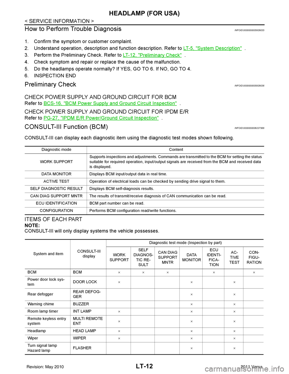
CONSULT-III can display each diagnostic item us ing the diagnostic test modes shown following.
ITEMS OF EACH PART
NOTE:
CONSULT-III will only display systems the vehicle possesses.
Diagnostic mode Content
WORK SUPPORT Supports inspections and adjustments. Commands are transmitted to the BCM for setting the status
suitable for required operation, input/output signals are received from the BCM and received data
is displayed.
DATA MONITOR Displays BCM input/output data in real time. ACTIVE TEST Operation of electrical loads can be checked by sending drive signal to them.
SELF DIAGNOSTIC RESULT Displays BCM self-diagnosis results.
CAN DIAG SUPPORT MNTR The results of transmit/receive diagnosis of CAN communication can be read. ECU IDENTIFICATION BCM part number can be read.CONFIGURATION Performs BCM configuration read/write functions.
System and item CONSULT-III
display Diagnostic test mode (Inspection by part)
WORK
SUPPORT SELF
DIAGNOS- TIC RE-SULT CAN DIAG
SUPPORT
MNTR DATA
MONITOR ECU
IDENTI- FICA-TION AC-
TIVE
TEST CON-
FIGU-
RATION
BCM BCM×× × × ×
Power door lock sys-
tem DOOR LOCK
×× ×
Rear defogger REAR DEFOG-
GER ××
Warning chime BUZZER ××
Room lamp timer INT LAMP ×× ×
Remote keyless entry
system MULTI REMOTE
ENT
××
×
Headlamp HEAD LAMP×× ×
Wiper WIPER×× ×
Turn signal lamp
Hazard lamp FLASHER
××
Revision: May 2010 2011 Versa
Page 3048 of 3787
LT-16
< SERVICE INFORMATION >
HEADLAMP (FOR USA)
Without CONSULT-III
1. Start auto active test. Refer to PG-20, "
Auto Active Test" .
2. Make sure headlamp high beam operates.
OK or NG
OK >> GO TO 3.
NG >> GO TO 4.
3.CHECK IPDM E/R
1. Select “IPDM E/R” on CONSULT-III. Select “DATA MONITOR” on “SELECT DIAG MODE” screen.
2. Make sure “HL HI REQ” turns ON when lighting switch is in high position.
OK or NG
OK >> Replace IPDM E/R. Refer to PG-28, "Removal and Installation of IPDM E/R" .
NG >> Replace BCM. Refer to BCS-19, "
Removal and Installation of BCM" .
4.HEADLAMP HIGH BEAM FUSE INSPECTION
Inspect 10A fuse No. 34 (RH) and fuse No. 35 (LH).
OK or NG
OK >> GO TO 5.
NG >> Repair harness.
5.BULB INSPECTION
Inspect inoperative headlamp bulbs.
OK or NG
OK >> GO TO 6.
NG >> Replace headlamp bulb. LT-24, "
Bulb Replacement" .
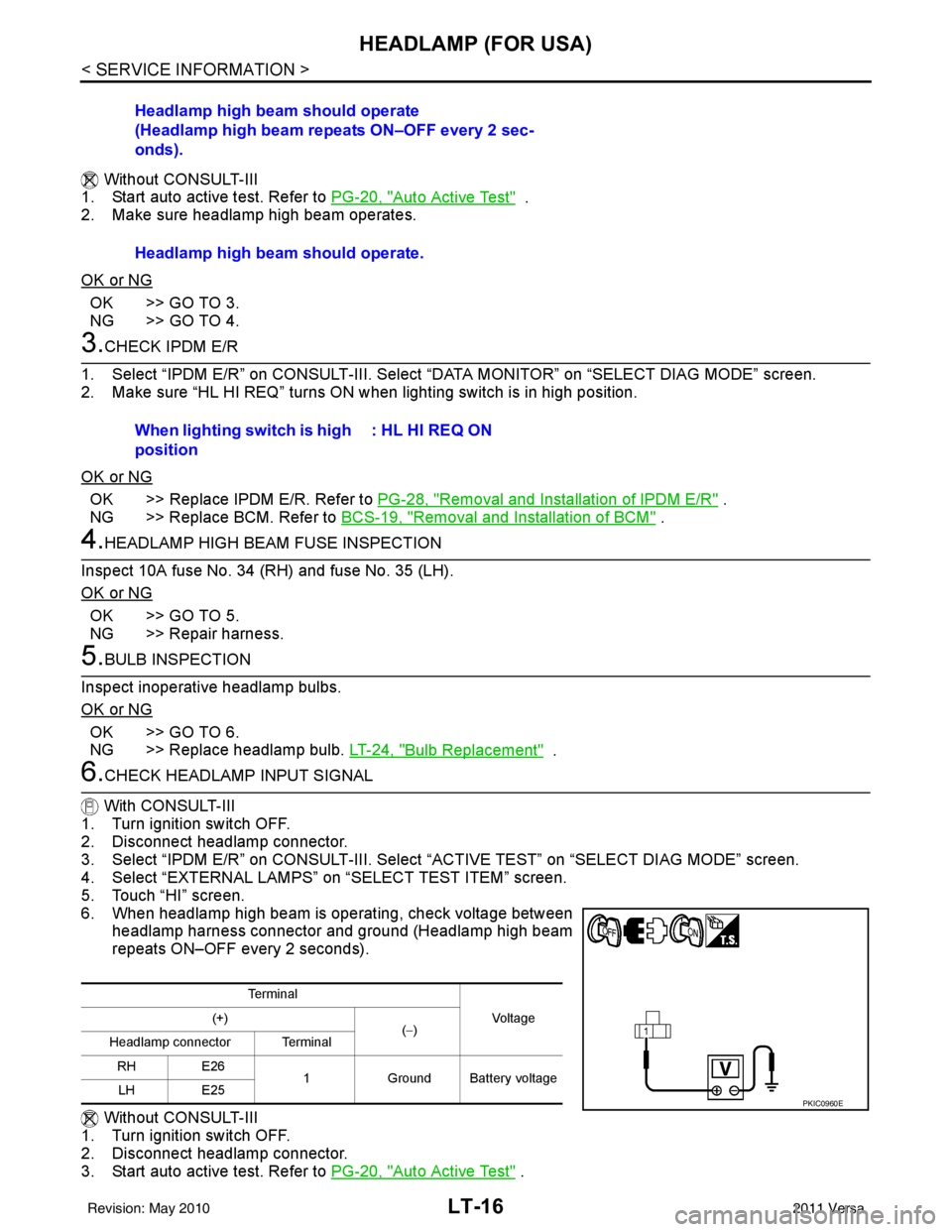
6.CHECK HEADLAMP INPUT SIGNAL
With CONSULT-III
1. Turn ignition switch OFF.
2. Disconnect headlamp connector.
3. Select “IPDM E/R” on CONSULT-III. Select “ACTIVE TEST” on “SELECT DIAG MODE” screen.
4. Select “EXTERNAL LAMPS” on “SELECT TEST ITEM” screen.
5. Touch “HI” screen.
6. When headlamp high beam is operating, check voltage between headlamp harness connector and ground (Headlamp high beam
repeats ON–OFF every 2 seconds).
Without CONSULT-III
1. Turn ignition switch OFF.
2. Disconnect headlamp connector.
3. Start auto active test. Refer to PG-20, "
Auto Active Test" .
Headlamp high beam should operate
(Headlamp high beam repeats ON–OFF every 2 sec-
onds).
Headlamp high beam should operate.
When lighting switch is high
position
: HL HI REQ ON
Te r m i n a l
Vo l ta g e
(+)
(−)
Headlamp connector Terminal
RH E26 1Ground Battery voltage
LH E25
PKIC0960E
Revision: May 2010 2011 Versa
Page 3051 of 3787
HEADLAMP (FOR USA)LT-19
< SERVICE INFORMATION >
C
DE
F
G H
I
J
L
M A
B
LT
N
O P
Headlamp Low Beam Does No t Illuminate (Both Sides)INFOID:0000000005929042
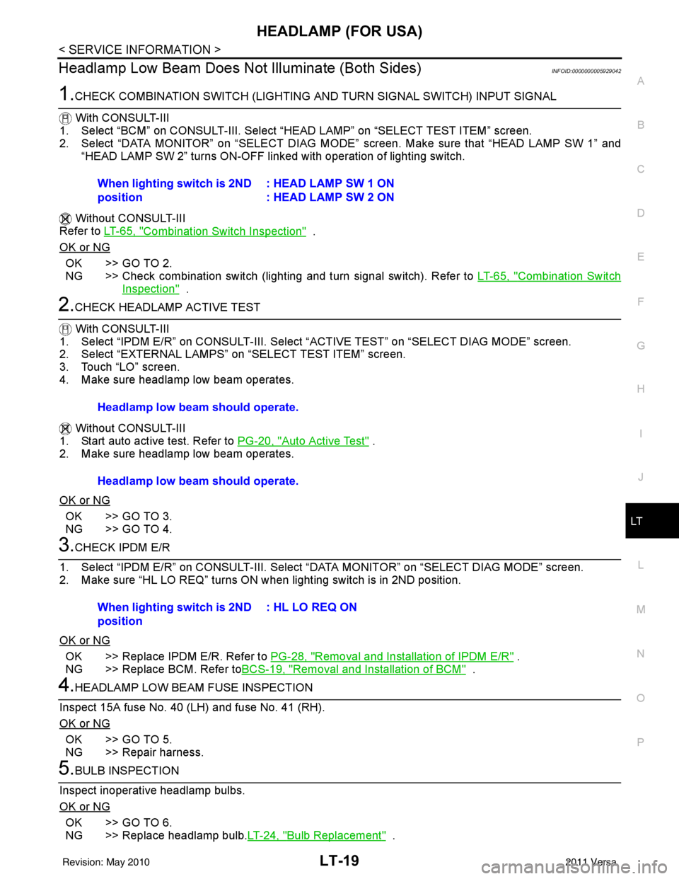
1.CHECK COMBINATION SWITCH (LIGHTING AND TURN SIGNAL SWITCH) INPUT SIGNAL
With CONSULT-III
1. Select “BCM” on CONSULT-III. Select “HEAD LAMP” on “SELECT TEST ITEM” screen.
2. Select “DATA MONITOR” on “SELECT DIAG MODE” screen. Make sure that “HEAD LAMP SW 1” and
“HEAD LAMP SW 2” turns ON-OFF li nked with operation of lighting switch.
Without CONSULT-III
Refer to LT-65, "
Combination Switch Inspection" .
OK or NG
OK >> GO TO 2.
NG >> Check combination switch (lighting and turn signal switch). Refer to LT-65, "
Combination Switch
Inspection" .
2.CHECK HEADLAMP ACTIVE TEST
With CONSULT-III
1. Select “IPDM E/R” on CONSUL T-III. Select “ACTIVE TEST” on “SELECT DIAG MODE” screen.
2. Select “EXTERNAL LAMPS” on “SELECT TEST ITEM” screen.
3. Touch “LO” screen.
4. Make sure headlamp low beam operates.
Without CONSULT-III
1. Start auto active test. Refer to PG-20, "
Auto Active Test" .
2. Make sure headlamp low beam operates.
OK or NG
OK >> GO TO 3.
NG >> GO TO 4.
3.CHECK IPDM E/R
1. Select “IPDM E/R” on CONSUL T-III. Select “DATA MONITOR” on “SELECT DIAG MODE” screen.
2. Make sure “HL LO REQ” turns ON when lighting switch is in 2ND position.
OK or NG
OK >> Replace IPDM E/R. Refer to PG-28, "Removal and Installation of IPDM E/R" .
NG >> Replace BCM. Refer to BCS-19, "
Removal and Installation of BCM" .
4.HEADLAMP LOW BEAM FUSE INSPECTION
Inspect 15A fuse No. 40 (LH) and fuse No. 41 (RH).
OK or NG
OK >> GO TO 5.
NG >> Repair harness.
5.BULB INSPECTION
Inspect inoperative headlamp bulbs.
OK or NG
OK >> GO TO 6.
NG >> Replace headlamp bulb. LT-24, "
Bulb Replacement" .
When lighting switch is 2ND
position
: HEAD LAMP SW 1 ON
: HEAD LAMP SW 2 ON
Headlamp low beam should operate.
Headlamp low beam should operate.
When lighting switch is 2ND
position: HL LO REQ ON
Revision: May 2010
2011 Versa
Page 3061 of 3787
HEADLAMP (FOR CANADA) - DAYTIME LIGHT SYSTEM -
LT-29
< SERVICE INFORMATION >
C
D E
F
G H
I
J
L
M A
B
LT
N
O P
• to IPDM E/R terminal 56,
• through 10A fuse (No. 34, located in IPDM E/R) and
• through both de-energized headlamp high relays
• to 10A fuse (No. 35, located in IPDM E/R),
• through IPDM E/R terminal 55
• to front combination lamp LH terminal high beam 1.
Ground is supplied
• to front combination lamp LH terminal 2
• through grounds E15 and E24,
• to daytime light relay 1 terminal 1
• through IPDM E/R terminal 6.
With power and ground supplied, high beam headlamps illuminate at reduced intensity.
COMBINATION SWITCH READING FUNCTION
Refer to BCS-4, "System Description" .
EXTERIOR LAMP BATTERY SAVER CONTROL
Refer to LT-74, "System Description" .
CAN Communication System DescriptionINFOID:0000000005929051
Refer to LAN-7, "System Description" .
Revision: May 2010 2011 Versa
Page 3066 of 3787
LT-34
< SERVICE INFORMATION >
HEADLAMP (FOR CANADA) - DAYTIME LIGHT SYSTEM -
Terminal and Reference Value for BCM
INFOID:0000000005929054
Refer to BCS-12, "Terminal and Reference Value for BCM"
Terminal and Reference Value for IPDM E/RINFOID:0000000005929055
Refer to PG-25, "Terminal and Reference Value for IPDM E/R" .
LKWA0325E
Revision: May 2010 2011 Versa
Page 3067 of 3787
HEADLAMP (FOR CANADA) - DAYTIME LIGHT SYSTEM -
LT-35
< SERVICE INFORMATION >
C
D E
F
G H
I
J
L
M A
B
LT
N
O P
How to Perform Trouble DiagnosisINFOID:0000000005929056
1. Confirm the symptom or customer complaint.
2. Understand operation, description and function description. Refer to LT-27, "
System Description" .
3. Perform the Preliminary Check. Refer to LT-35, "
Preliminary Check" .
4. Check symptom and repair or replace the cause of the malfunction.
5. Does the daytime light system operate norma lly? If YES, GO TO 6. If NO, GO TO 4.
6. INSPECTION END
Preliminary CheckINFOID:0000000005929057
CHECK BCM CONFIGURATION
1.CHECK BCM CONFIGURATION
Confirm BCM configuration for "DTRL" is set to "WITH". Refer to BCS-19, "
Configuration" .
OK or NG
OK >> Continue preliminary check. Refer to BCS-16, "BCM Power Supply and Ground Circuit Inspec-
tion" .
NG >> Change BCM configuration for "DTRL" to "WITH". Refer to BCS-19, "
Configuration" .
CHECK POWER SUPPLY AND GROUND CIRCUIT FOR BCM
Refer to BCS-16, "BCM Power Supply and Ground Circuit Inspection" .
CHECK POWER SUPPLY AND GROUND CIRCUIT FOR IPDM E/R
Refer to PG-27, "IPDM E/R Power/Ground Circuit Inspection" .
CONSULT-III Function (BCM)INFOID:0000000005929058
Refer to LT-12, "CONSULT-III Function (BCM)" .
CONSULT-III Function (IPDM E/R)INFOID:0000000005929059
Refer to PG-18, "CONSULT-III Function (IPDM E/R)" .
Daytime Light Control Does Not Operate Properly (High Beam Headlamps Operate
Properly)
INFOID:0000000005929060
1.CHECK DAYTIME LIGHT RELAY 1 FUSE
Inspect daytime light relay fuse 10A fuse (No. 26, located in the fuse and fusible link box).
OK or NG
OK >> GO TO 2.
NG >> Repair harness.
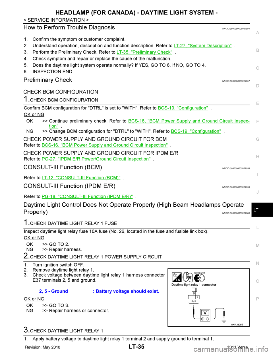
2.CHECK DAYTIME LIGHT RELAY 1 POWER SUPPLY CIRCUIT
1. Turn ignition switch OFF.
2. Remove daytime light relay 1.
3. Check voltage between daytime light relay 1 harness connector E37 terminals 2, 5 and ground.
OK or NG
OK >> GO TO 3.
NG >> Repair harness or connector.
3.CHECK DAYTIME LIGHT RELAY 1
1. Apply battery voltage to daytime light relay 1 terminal 2 and supply ground to terminal 1. 2, 5 - Ground
: Battery voltage should exist.
WKIA3305E
Revision: May 2010 2011 Versa
Page 3068 of 3787
LT-36
< SERVICE INFORMATION >
HEADLAMP (FOR CANADA) - DAYTIME LIGHT SYSTEM -
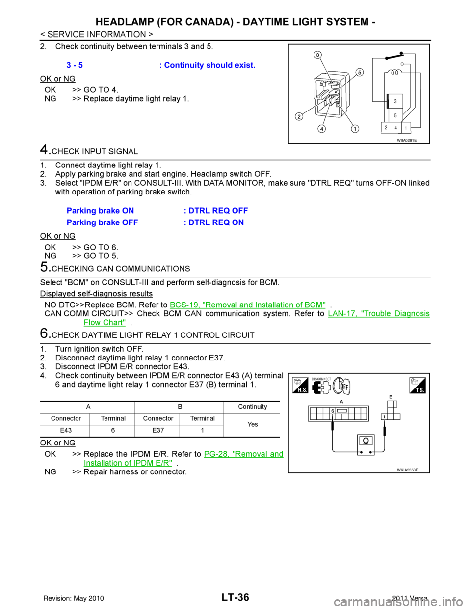
2. Check continuity between terminals 3 and 5.
OK or NG
OK >> GO TO 4.
NG >> Replace daytime light relay 1.
4.CHECK INPUT SIGNAL
1. Connect daytime light relay 1.
2. Apply parking brake and start engine. Headlamp switch OFF.
3. Select "IPDM E/R" on CONSULT-III. With DATA MO NITOR, make sure "DTRL REQ" turns OFF-ON linked
with operation of parking brake switch.
OK or NG
OK >> GO TO 6.
NG >> GO TO 5.
5.CHECKING CAN COMMUNICATIONS
Select "BCM" on CONSULT-III and perform self-diagnosis for BCM.
Displayed self-diagnosis results
NO DTC>>Replace BCM. Refer to BCS-19, "Removal and Installation of BCM" .
CAN COMM CIRCUIT>> Check BCM CAN communication system. Refer to LAN-17, "
Trouble Diagnosis
Flow Chart" .
6.CHECK DAYTIME LIGHT RELAY 1 CONTROL CIRCUIT
1. Turn ignition switch OFF.
2. Disconnect daytime light relay 1 connector E37.
3. Disconnect IPDM E/R connector E43.
4. Check continuity between IPDM E/R connector E43 (A) terminal 6 and daytime light relay 1 connector E37 (B) terminal 1.
OK or NG
OK >> Replace the IPDM E/R. Refer to PG-28, "Removal and
Installation of IPDM E/R" .
NG >> Repair harness or connector. 3 - 5
: Continuity should exist.
WIIA0291E
Parking brake ON : DTRL REQ OFF
Parking brake OFF : DTRL REQ ON
ABC on tin uit y
Connector Terminal Connector Terminal Ye s
E43 6E37 1
WKIA5553E
Revision: May 2010 2011 Versa