2011 NISSAN TIIDA Bcs
[x] Cancel search: BcsPage 3542 of 3787
TROUBLE DIAGNOSISRF-19
< FUNCTION DIAGNOSIS >
C
DE
F
G H
J
K L
M A
B
RF
N
O P
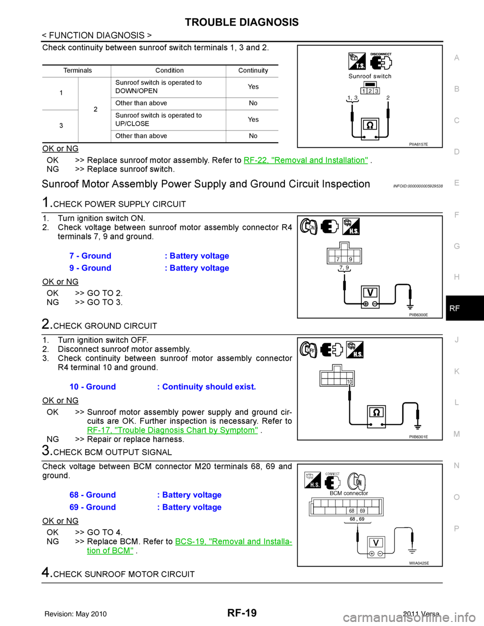
Check continuity between sunroof switch terminals 1, 3 and 2.
OK or NG
OK >> Replace sunroof motor assembly. Refer to RF-22, "Removal and Installation" .
NG >> Replace sunroof switch.
Sunroof Motor Assembly Power Supply and Ground Circuit InspectionINFOID:0000000005929538
1.CHECK POWER SUPPLY CIRCUIT
1. Turn ignition switch ON.
2. Check voltage between sunroof motor assembly connector R4 terminals 7, 9 and ground.
OK or NG
OK >> GO TO 2.
NG >> GO TO 3.
2.CHECK GROUND CIRCUIT
1. Turn ignition switch OFF.
2. Disconnect sunroof motor assembly.
3. Check continuity between sunroof motor assembly connector R4 terminal 10 and ground.
OK or NG
OK >> Sunroof motor assembly power supply and ground cir- cuits are OK. Further inspection is necessary. Refer to
RF-17, "
Trouble Diagnosis Chart by Symptom" .
NG >> Repair or replace harness.
3.CHECK BCM OUTPUT SIGNAL
Check voltage between BCM connector M20 terminals 68, 69 and
ground.
OK or NG
OK >> GO TO 4.
NG >> Replace BCM. Refer to BCS-19, "
Removal and Installa-
tion of BCM" .
4.CHECK SUNROOF MOTOR CIRCUIT
Terminals ConditionContinuity
1 2Sunroof switch is operated to
DOWN/OPEN
Ye s
Other than above No
3 Sunroof switch is operated to
UP/CLOSE
Ye s
Other than above No
PIIA6157E
7 - Ground: Battery voltage
9 - Ground : Battery voltage
PIIB6300E
10 - Ground: Continuity should exist.
PIIB6301E
68 - Ground : Battery voltage
69 - Ground : Battery voltage
WIIA0425E
Revision: May 2010 2011 Versa
Page 3544 of 3787
TROUBLE DIAGNOSISRF-21
< FUNCTION DIAGNOSIS >
C
DE
F
G H
J
K L
M A
B
RF
N
O P
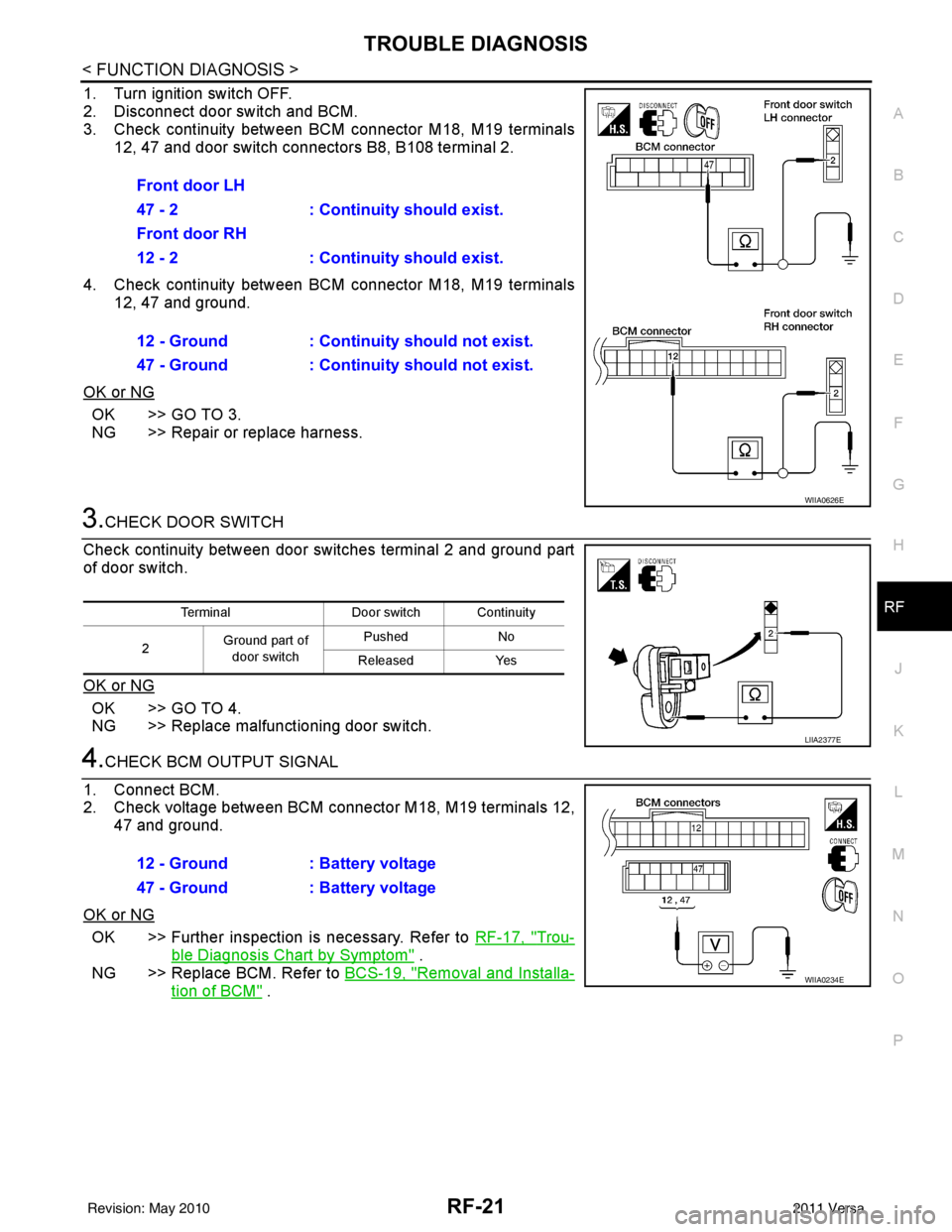
1. Turn ignition switch OFF.
2. Disconnect door switch and BCM.
3. Check continuity between BCM connector M18, M19 terminals 12, 47 and door switch connectors B8, B108 terminal 2.
4. Check continuity between BCM connector M18, M19 terminals 12, 47 and ground.
OK or NG
OK >> GO TO 3.
NG >> Repair or replace harness.
3.CHECK DOOR SWITCH
Check continuity between door switches terminal 2 and ground part
of door switch.
OK or NG
OK >> GO TO 4.
NG >> Replace malfunctioning door switch.
4.CHECK BCM OUTPUT SIGNAL
1. Connect BCM.
2. Check voltage between BCM connector M18, M19 terminals 12, 47 and ground.
OK or NG
OK >> Further inspection is necessary. Refer to RF-17, "Trou-
ble Diagnosis Chart by Symptom" .
NG >> Replace BCM. Refer to BCS-19, "
Removal and Installa-
tion of BCM" .
Front door LH
47 - 2 : Continuity should exist.
Front door RH
12 - 2 : Continuity should exist.
12 - Ground : Continuity should not exist.
47 - Ground : Continuity should not exist.
WIIA0626E
Terminal
Door switch Continuity
2 Ground part of
door switch Pushed
No
Released Yes
LIIA2377E
12 - Ground : Battery voltage
47 - Ground : Battery voltage
WIIA0234E
Revision: May 2010 2011 Versa
Page 3730 of 3787
WT-12
< SERVICE INFORMATION >
TROUBLE DIAGNOSES
TROUBLE DIAGNOSES
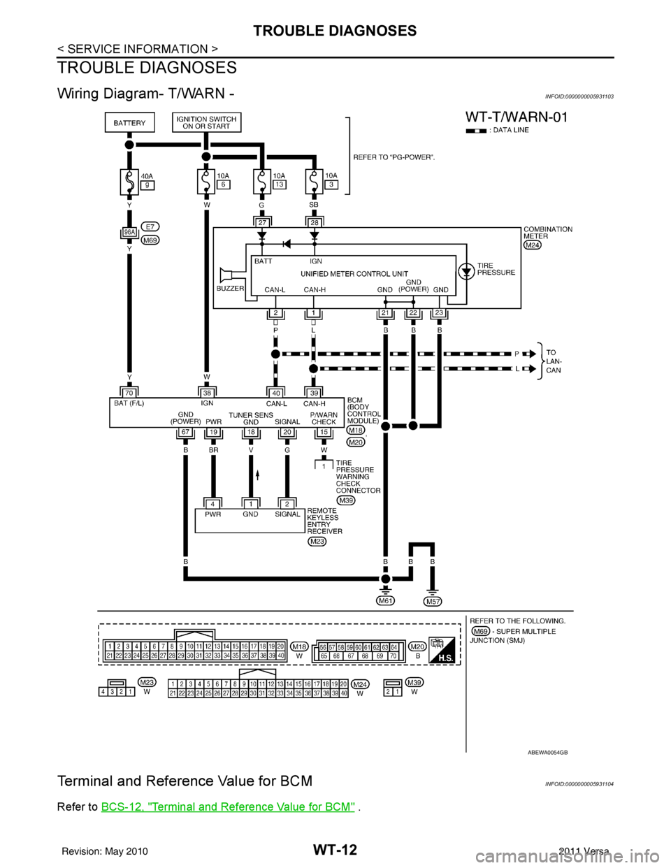
Wiring Diagram- T/WARN -INFOID:0000000005931103
Terminal and Reference Value for BCMINFOID:0000000005931104
Refer to BCS-12, "Terminal and Reference Value for BCM" .
ABEWA0054GB
Revision: May 2010 2011 Versa
Page 3738 of 3787
WT-20
< SERVICE INFORMATION >
TROUBLE DIAGNOSIS FOR SELF-DIAGNOSTIC ITEMS
TROUBLE DIAGNOSIS FOR SELF-DIAGNOSTIC ITEMS
Data from Transmitter Not Being ReceivedINFOID:0000000005931112
MALFUNCTION CODE NO. 21, 22, 23 OR 24 (DTC C1708, C1709, C1710 OR C1711)
1.CHECK BCM
Drive for several minutes. Check all tire pressures with CONSULT-III.
Are all tire pressures displayed as 0 kPa?
YES >> GO TO 2.
NO >> GO TO 3.
2.CHECK REMOTE KEYLESS EN TRY RECEIVER CONNECTOR
Check remote keyless entry receiver connector for damage or loose connections.
OK or NG
OK >> Replace BCM, then GO TO 3. Refer to BCS-19, "Removal and Installation of BCM".
NG >> Repair or replace remote keyless entry receiver connector.
3.PERFORM ID REGISTRATION
Carry out ID registration of all transmitters. Refer to WT-13, "
ID Registration Procedure".
Is there a tire that cannot register ID?
YES >> Replace transmitter of the tire, then GO TO 5. Refer to WT-26, "Transmitter (Pressure Sensor)".
NO >> GO TO 4.
4.DRIVE VEHICLE
1. Drive at a speed of 40 km/h (25 MPH) or more for several minutes without stopping.
2. Check all tire pressures with CONSULT-III within 15 minutes after vehicle speed becomes 17 km/h (11 MPH).
Does
“DATA MONITOR ITEM” display tire pressure as normal without any warning lamp?
YES >> Inspection End.
NO >> GO TO 5.
5.ID REGISTRATION AND VEHICLE DRIVING
1. Carry out ID registration of all transmitters. Refer to WT-13, "
ID Registration Procedure".
2. Drive at a speed of 40 km/h (25 MPH) or more fo r 3 minutes, and then drive the vehicle at any speed for
10 minutes.
3. Check all tire pressures with CONSULT-III within 5 minutes.
Does
“DATA MONITOR ITEM” display tire pressure as normal without any warning lamp?
YES >> Inspection End.
NO >> GO TO the inspection applicable to DTC.
Transmitter MalfunctionINFOID:0000000005931113
MALFUNCTION CODE NO. 31, 32, 33, 34, 41, 42, 43, 44, 45, 46, 47 OR 48 (DTC C1712, C1713,
C1714, C1715, C1720, C1721, C1722, C1723, C1724, C1725, C1726 OR C1727)
1.PERFORM ID REGISTRATION
1. Carry out ID registration of all transmitters. Refer to WT-13, "
ID Registration Procedure".
2. Drive at a speed of 40 km/h (25 MPH) or more fo r 3 minutes, and then drive the vehicle at any speed for
10 minutes.
>> GO TO 2.
2.REPLACE TRANSMITTER
1. Check low tire pressure warning lamp again for fl ashing, replace malfunctioning transmitter. Refer to WT-
26, "Transmitter (Pressure Sensor)".
2. Carry out ID registration of all transmitters. Refer to WT-13, "
ID Registration Procedure".
Revision: May 2010 2011 Versa
Page 3739 of 3787
TROUBLE DIAGNOSIS FOR SELF-DIAGNOSTIC ITEMS
WT-21
< SERVICE INFORMATION >
C
D F
G H
I
J
K L
M A
B
WT
N
O P
Can ID registration of all transmitters be completed?
YES >> GO TO 3.
NO >> GO TO WT-20, "
Data from Transmitter Not Being Received".
3.DRIVE VEHICLE
1. Drive at a speed of 40 km/h (25 MPH) or more fo r 3 minutes, and then drive the vehicle at any speed for
10 minutes.
2. Check all tire pressures with CONSULT-III within 5 minutes.
Does
“DATA MONITOR ITEM” display tire pressure as normal without any warning lamp?
YES >> Inspection End.
NO >> Replace malfunctioning transmitter, and perform Step 3 again. Refer to WT-26, "
Transmitter
(Pressure Sensor)".
Transmitter Pressure MalfunctionINFOID:0000000005931114
MALFUNCTION CODE NO. 35, 36, 37 OR 38 (DTC C1716, C1717, C1718 OR C1719)
1.CHECK ALL TIRE PRESSURES
Check all tire pressures. Refer to WT-28, "
Tire".
Are there any tires with pressure of 64 psi or more?
YES >> Adjust tire pressure to specified value.
NO >> GO TO 2.
2.ID REGISTRATION AND VEHICLE DRIVING
1. Carry out ID registration of all transmitters. Refer to WT-13, "
ID Registration Procedure".
2. Drive at a speed of 40 km/h (25 MPH) or more for several minutes without stopping.
3. Check all tire pressures with CONSULT-III within 15 minutes after vehicle speed becomes 17 km/h (11 MPH).
Does
“DATA MONITOR ITEM” display 64 psi or more?
YES >> Replace transmitter. Refer to WT-26, "Transmitter (Pressure Sensor)". GO TO 3.
NO >> GO TO 3.
3.ID REGISTRATION AND VEHICLE DRIVING
1. Carry out ID registration of all transmitters. Refer to WT-13, "
ID Registration Procedure".
2. Drive at a speed of 40 km/h (25 MPH) or more fo r 3 minutes, and then drive the vehicle at any speed for
10 minutes.
3. Check all tire pressures with CONSULT-III within 5 minutes.
Does
“DATA MONITOR ITEM” display tire pressure as normal without any warning lamp?
YES >> Inspection End.
NO >> GO TO the inspection applicable to DTC.
Vehicle Speed SignalINFOID:0000000005931115
MALFUNCTION CODE NO. 52 (DTC C1729)
1.SELF-DIAGNOSTIC RESULT CHECK
Using CONSULT-III, check display contents in self-diagnostic results.
Is " CAN COMM CIRCUIT" displayed in the self-diagnosis display items?
YES >> Malfunction in CAN communication system. GO TO LAN-13, "CAN Diagnosis with CONSULT-III".
NO >> GO TO 2.
2.CHECK BCM
Perform BCM diagnosis. Refer to BCS-17, "
CONSULT-III Function (BCM)".
Inspection results OK?
OK >> Perform Vehicle Speed Sensor Inspection. Refer to EC-352, "Diagnosis Procedure" (HR16DE) or
EC-888, "
Diagnosis Procedure" (MR18DE).
NG >> Replace BCM. Refer to BCS-19, "
Removal and Installation of BCM".
Revision: May 2010 2011 Versa
Page 3740 of 3787
WT-22
< SERVICE INFORMATION >
TROUBLE DIAGNOSIS FOR SELF-DIAGNOSTIC ITEMS
Vehicle Ignition Signal
INFOID:0000000005931116
MALFUNCTION CODE NO. 54 (DTC C1735)
1.CAN IGNITION SIGNAL
Check BCM IGN RLY signal with CONSULT-III. Refer to BCS-12, "
Terminal and Reference Value for BCM".
Are the inspection results normal with the ignition switch ON?
YES >> GO TO 2.
NO >> Check CAN system. Refer to LAN-17, "
Trouble Diagnosis Flow Chart".
2.BCM POWER SUPPLY
Check BCM power supply (ignition ON). Refer to BCS-16, "
BCM Power Supply and Ground Circuit Inspec-
tion".
Is the power supply with the ignition switch ON normal?
YES >> GO TO 3.
NO >> Repair power supply as necessary.
3.DRIVE VEHICLE
Clear DTC and then test drive the vehicle and check the low tire pressure warning lamp.
Does the vehicle operate without any low tire pressure warning lamp?
YES >> Inspection End.
NO >> Replace BCM. Refer to BCS-19, "
Removal and Installation of BCM".
Revision: May 2010 2011 Versa
Page 3741 of 3787
TROUBLE DIAGNOSIS FOR SYMPTOMSWT-23
< SERVICE INFORMATION >
C
DF
G H
I
J
K L
M A
B
WT
N
O P
TROUBLE DIAGNOSIS FOR SYMPTOMS
Low Tire Pressure Warning Lamp Does Not Come On When Ignition Switch Is Turned
On
INFOID:0000000005931117
DIAGNOSTIC PROCEDURE
1.SELF-DIAGNOSTIC RESULT CHECK
Using CONSULT-III, check display contents in self-diagnostic results.
Is "CAN COMM CIRCUIT" displayed in the self-diagnosis display items?
YES >> Malfunction in CAN communication system. GO TO LAN-13, "CAN Diagnosis with CONSULT-
III".
NO >> GO TO 2.
2.CHECK COMBINATION METER
Check combination meter operation. Refer to DI-11, "
Self-Diagnosis Mode of Combination Meter".
Inspection results OK?
OK >> GO TO 3.
NG >> Replace combination meter. Refer to IP-12, "
Removal and Installation".
3.CHECK LOW TIRE PRE SSURE WARNING LAMP
Disconnect BCM harness connector.
Does the low tire pressure warning lamp activate?
YES >> Replace BCM. Refer to BCS-19, "Removal and Installation of BCM".
NO >> Check combination meter operation. Refer to DI-11, "
Self-Diagnosis Mode of Combination
Meter".
Low Tire Pressure Warning Lamp Stays On When Ignition Switch Is Turned On
INFOID:0000000005931118
DIAGNOSTIC PROCEDURE
1.CHECK BCM CONNECTORS
1. Turn ignition switch OFF.
2. Disconnect BCM harness connectors M18 and M20.
3. Check terminals for damage or loose connections.
Inspection results OK?
OK >> GO TO 2.
NG >> Repair or replace damaged parts.
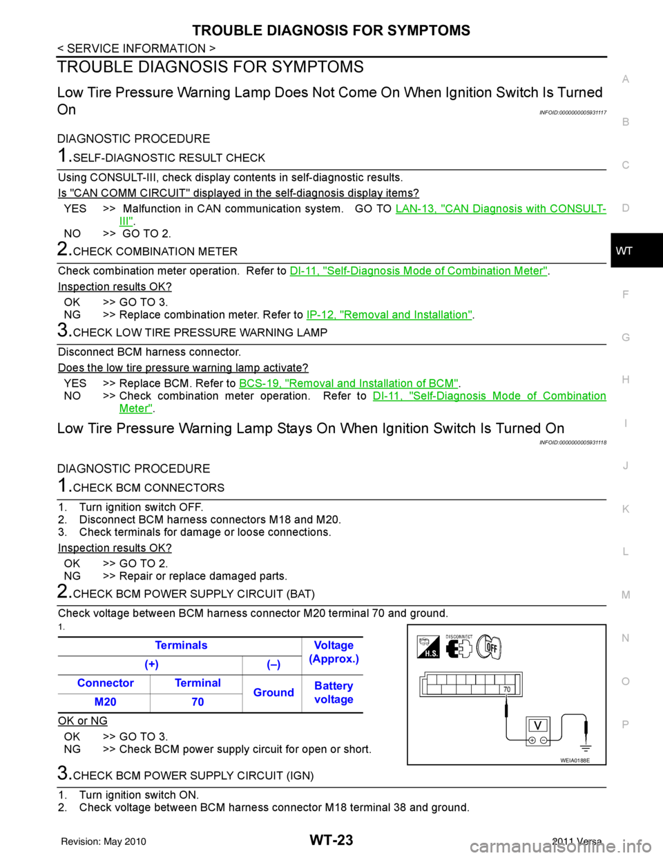
2.CHECK BCM POWER SUPPLY CIRCUIT (BAT)
Check voltage between BCM harness connector M20 terminal 70 and ground.
1.
OK or NG
OK >> GO TO 3.
NG >> Check BCM power supply circuit for open or short.
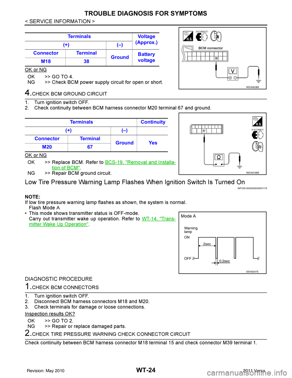
3.CHECK BCM POWER SUPPLY CIRCUIT (IGN)
1. Turn ignition switch ON.
2. Check voltage between BCM harness connector M18 terminal 38 and ground. Terminals Voltage
(Approx.)
(+) (–)
Connector Terminal GroundBattery
voltage
M20 70
WEIA0188E
Revision: May 2010 2011 Versa
Page 3742 of 3787
WT-24
< SERVICE INFORMATION >
TROUBLE DIAGNOSIS FOR SYMPTOMS
OK or NG
OK >> GO TO 4.
NG >> Check BCM power supply circuit for open or short.
4.CHECK BCM GROUND CIRCUIT
1. Turn ignition switch OFF.
2. Check continuity between BCM harnes s connector M20 terminal 67 and ground.
OK or NG
OK >> Replace BCM. Refer to BCS-19, "Removal and Installa-
tion of BCM".
NG >> Repair BCM ground circuit.
Low Tire Pressure Warning Lamp Flashes When Ignition Switch Is Turned On
INFOID:0000000005931119
NOTE:
If low tire pressure warning lamp flashes as shown, the system is normal. Flash Mode A
• This mode shows transmitter status is OFF-mode. Carry out transmitter wake up operation. Refer to WT-14, "
Trans-
mitter Wake Up Operation".
DIAGNOSTIC PROCEDURE
1.CHECK BCM CONNECTORS
1. Turn ignition switch OFF.
2. Disconnect BCM harness connectors M18 and M20.
3. Check terminals for damage or loose connections.
Inspection results OK?
OK >> GO TO 2.
NG >> Repair or replace damaged parts.
2.CHECK TIRE PRESSURE WARNING CHECK CONNECTOR CIRCUIT
Check continuity between BCM harness connector M 18 terminal 15 and check connector M39 terminal 1.
Terminals
Voltage
(Approx.)
(+) (–)
Connector Terminal GroundBattery
voltage
M18 38
WEIA0038E
Terminals Continuity
(+) (–)
Connector Terminal Ground Yes
M20 67
WEIA0189E
SEIA0347E
Revision: May 2010 2011 Versa