2011 NISSAN TIIDA Bcs
[x] Cancel search: BcsPage 773 of 3787
NATS (NISSAN ANTI-THEFT SYSTEM)BL-263
< SERVICE INFORMATION >
C
DE
F
G H
J
K L
M A
B
BL
N
O P
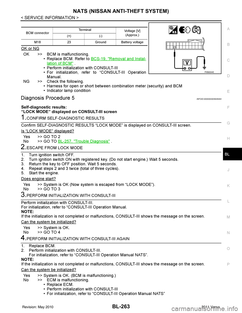
OK or NG
OK >> BCM is malfunctioning. • Replace BCM. Refer to BCS-19, "
Removal and Instal-
lation of BCM" .
• Perform initialization with CONSULT-III
• For initialization, refer to “CONSULT-III Operation Manual.
NG >> Check the following. • Harness for open or short between combination meter (security) and BCM
• Indicator lamp condition
Diagnosis Procedure 5INFOID:0000000005929444
Self-diagnostic results:
“LOCK MODE” displayed on CONSULT-III screen
1.CONFIRM SELF-DIAGNOSTIC RESULTS
Confirm SELF-DIAGNOSTIC RESULTS “LOCK MODE” is displayed on CONSULT-III screen.
Is
“LOCK MODE” displayed?
Yes >> GO TO 2
No >> GO TO BL-257, "
Trouble Diagnosis" .
2.ESCAPE FROM LOCK MODE
1. Turn ignition switch OFF.
2. Turn ignition switch ON with registered key. (Do not start engine.) Wait 5 seconds.
3. Return the key to OFF position. Wait 5 seconds.
4. Repeat steps 2 and 3 twice (total of three cycles).
5. Start the engine.
Does engine start?
Yes >> System is OK (Now system is escaped from “LOCK MODE”).
No >> GO TO 3
3.PERFORM INITIALIZATION WITH CONSULT-III
Perform initialization with CONSULT-III.
For initialization, refer to “CONSULT-III Operation Manual.
NOTE:
If the initialization is not completed or malf unctions, CONSULT-III shows the message on the screen.
Can the system be initialized?
Yes >> System is OK.
No >> GO TO 4
4.PERFORM INITIALIZATION WITH CONSULT-III AGAIN
1. Replace BCM.
2. Perform initialization with CONSULT-III. For initialization, refer to “CON SULT-III Operation Manual NATS”.
NOTE:
If the initialization is not completed or malf unctions, CONSULT-III shows the message on the screen.
Can the system be initialized?
Yes >> System is OK. (BCM is malfunctioning.)
No >> ECM is malfunctioning. • Replace ECM.
• Perform initialization with CONSULT-III
• For initialization, refer to “CONSULT-III Operation Manual NATS”
BCM connector Terminal
Voltage [V]
(Approx.)
(+) (-)
M18 23Ground Battery voltage
PIIB6594E
Revision: May 2010 2011 Versa
Page 774 of 3787
BL-264
< SERVICE INFORMATION >
NATS (NISSAN ANTI-THEFT SYSTEM)
Diagnosis Procedure 6
INFOID:0000000005929445
Self-diagnostic results:
“DIFFERENCE OF KEY” disp layed on CONSULT-III screen
1.CONFIRM SELF-DIAGNOSTIC RESULTS
Confirm SELF-DIAGNOSTIC RESU LTS “DIFFERENCE OF KEY” displayed on CONSULT-III screen.
Is
“DIFFERENCE OF KEY” displayed?
YES >> GO TO 2
NO >> GO TO BL-257, "
Trouble Diagnosis".
2.PERFORM INITIALIZATION WITH CONSULT-III
Perform initialization with CONSULT-III. Re-register all NATS ignition key IDs.
For initialization and registration of NATS ignition key IDs, refer to CONSULT-III Operation Manual.
NOTE:
If the initialization is not completed or ma lfunctions, CONSULT-III shows message on the screen.
Can the system be initialized and can the engine be started with re-registered NATS ignition key?
YES >> • Ignition key ID was unregistered.
NO >> • BCM is malfunctioning. • Replace BCM. Refer to BCS-19, "
Removal and Installation of BCM".
• Perform initialization with CONSULT-III.
• For initialization, refer to CONSULT-III Operation Manual.
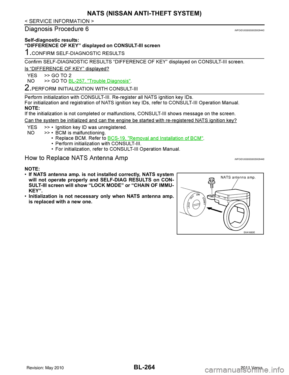
How to Replace NATS Antenna AmpINFOID:0000000005929446
NOTE:
• If NATS antenna amp. is not installed correctly, NATS system
will not operate properly and SELF-DIAG RESULTS on CON-
SULT-III screen will show “LOCK MODE” or “CHAIN OF IMMU-
KEY”.
• Initialization is not necessary only when NATS antenna amp.
is replaced with a new one.
SIIA1683E
Revision: May 2010 2011 Versa
Page 1286 of 3787
WARNING CHIMEDI-47
< SERVICE INFORMATION >
C
DE
F
G H
I
J
L
M A
B
DI
N
O P
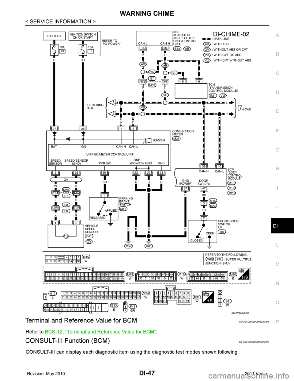
Terminal and Reference Value for BCMINFOID:0000000005929194
Refer to BCS-12, "Terminal and Reference Value for BCM".
CONSULT-III Function (BCM)INFOID:0000000005929195
CONSULT-III can display each diagnostic item using the diagnostic test modes shown following.
ABNWA0848GB
Revision: May 2010 2011 Versa
Page 1288 of 3787
WARNING CHIMEDI-49
< SERVICE INFORMATION >
C
DE
F
G H
I
J
L
M A
B
DI
N
O P
1.CHECK BCM
Perform self-diagnosis of BCM. Refer to DI-47, "
CONSULT-III Function (BCM)".
Self
-diagnostic results content
No malfunction detected>> GO TO 2.
Malfunction detected>> Check applicable parts, and repair or replace corresponding parts.
2.CHECK COMBINATION METER
Perform self-diagnosis of combination meter. Refer to DI-13, "
CONSULT-III Function (METER/M&A)".
Self
-diagnostic results content
No malfunction detected>> Inspection End.
Malfunction detected>> Check applicable parts, and repair or replace corresponding parts.
SYMPTOM CHART
Combination Meter Buzzer Circuit InspectionINFOID:0000000005929197
1.CHECK CHIME OPERATION
1. Select “BUZZER” of “BCM” on CONSULT-III.
2. Perform “LIGHT WARN ALM” or “IGN KEY WARN ALM” of “ACTIVE TEST”.
Does chime sound?
YES >> Combination meter buzzer circuit is OK. Return to DI-48, "Trouble Diagnosis".
NO >> GO TO 2.
2.CHECK COMBINATION METER INPUT SIGNAL
1. Select “METER/M&A” on CONSULT-III.
2. Turn on hazard switch or lighting switch while monitoring “BUZZER” of “DATA MONITOR” and check
operation status.
OK or NG
Symptom Diagnoses/Service procedure
All warning chime systems do not activate. Perform the following inspections.
•
DI-49, "
Combination Meter Buzzer Circuit Inspection"
•DI-50, "Front Door Switch LH Signal Inspection"
If above check is OK, replace BCM. Refer to BCS-19, "Removal
and Installation of BCM".
Key warning chime
does not activate. Without Intelligent Key.
Perform
DI-51, "
Key Switch Signal Inspection (Without Intelligent
Key)".
If above check is OK, replace BCM. Refer to BCS-19, "
Removal
and Installation of BCM".
With Intelligent Key, when mechanical key
is used. Perform
DI-52, "
Key Switch and Ignition Knob Switch Signal In-
spection (With Intelligent Key, When Mechanical Key Is Used)".
If above check is OK, replace BCM. Refer to BCS-19, "
Removal
and Installation of BCM".
With Intelligent Key, when Intelligent Key
is carried with the driver. Refer to BL-119, "
Trouble Diagnosis Symptom Chart".
Light warning chime does not activate. Perform
DI-54, "
Lighting Switch Signal Inspection".
If above check is OK, replace BCM. Refer to BCS-19, "
Removal
and Installation of BCM".
Parking brake warning chime does not activate Perform the following inspections
•
DI-54, "
Parking Brake Switch Signal Inspection"
•DI-16, "Vehicle Speed Signal Inspection"
“BUZZER”
While hazard switch or
lighting switch is ON : ON and OFF repeatedly
Except above : OFF
Revision: May 2010 2011 Versa
Page 1289 of 3787
DI-50
< SERVICE INFORMATION >
WARNING CHIME
OK >> Check battery power supply circuit of combination meter. If OK, replace combination meter. Referto IP-12, "
Removal and Installation".
NG >> Replace BCM. Refer to BCS-19, "
Removal and Installation of BCM".
Front Door Switch LH Signal InspectionINFOID:0000000005929198
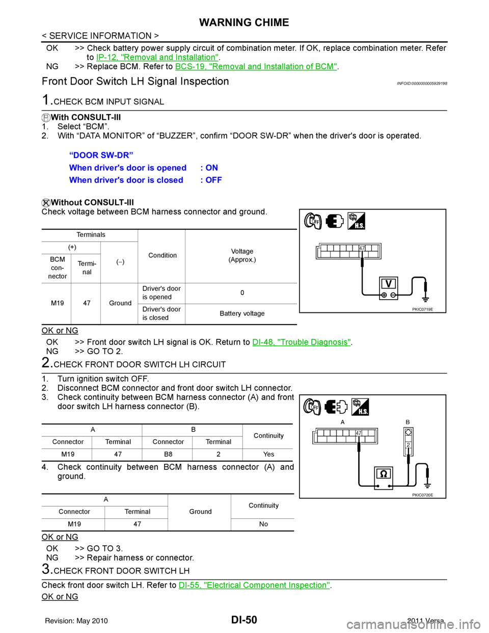
1.CHECK BCM INPUT SIGNAL
With CONSULT-III
1. Select “BCM”.
2. With “DATA MONITOR” of “BUZZER”, confirm “DOOR SW-DR” when the driver's door is operated.
Without CONSULT-III
Check voltage between BCM harness connector and ground.
OK or NG
OK >> Front door switch LH signal is OK. Return to DI-48, "Trouble Diagnosis".
NG >> GO TO 2.
2.CHECK FRONT DOOR SWITCH LH CIRCUIT
1. Turn ignition switch OFF.
2. Disconnect BCM connector and front door switch LH connector.
3. Check continuity between BCM harness connector (A) and front door switch LH harness connector (B).
4. Check continuity between BCM harness connector (A) and ground.
OK or NG
OK >> GO TO 3.
NG >> Repair harness or connector.
3.CHECK FRONT DOOR SWITCH LH
Check front door switch LH. Refer to DI-55, "
Electrical Component Inspection".
OK or NG
“DOOR SW-DR”
When driver's door is opened : ON
When driver's door is closed : OFF
Te r m i n a l s
Condition Vol tag e
(Approx.)
(+)
(−)
BCM
con-
nector Te r m i -
nal
M19 47 Ground Driver's door
is opened
0
Driver's door
is closed Battery voltage
PKIC0719E
AB
Continuity
Connector Terminal Connector Terminal
M19 47B8 2Yes
A GroundContinuity
Connector Terminal
M19 47 No
PKIC0720E
Revision: May 2010 2011 Versa
Page 1290 of 3787
WARNING CHIMEDI-51
< SERVICE INFORMATION >
C
DE
F
G H
I
J
L
M A
B
DI
N
O P
OK >> Replace BCM. Refer to BCS-19, "Removal and Installation of BCM".
NG >> Replace front door switch LH.
Key Switch Signal Inspection (Without Intelligent Key)INFOID:0000000005929199
1.CHECK FUSE
Check if the key switch and key lock solenoid 10A fuse [No. 14, located in the fuse block (J/B)] is blown.
OK or NG
OK >> GO TO 2.
NG >> Be sure to repair the cause of malfunction before installing new fuse. Refer to PG-4
.
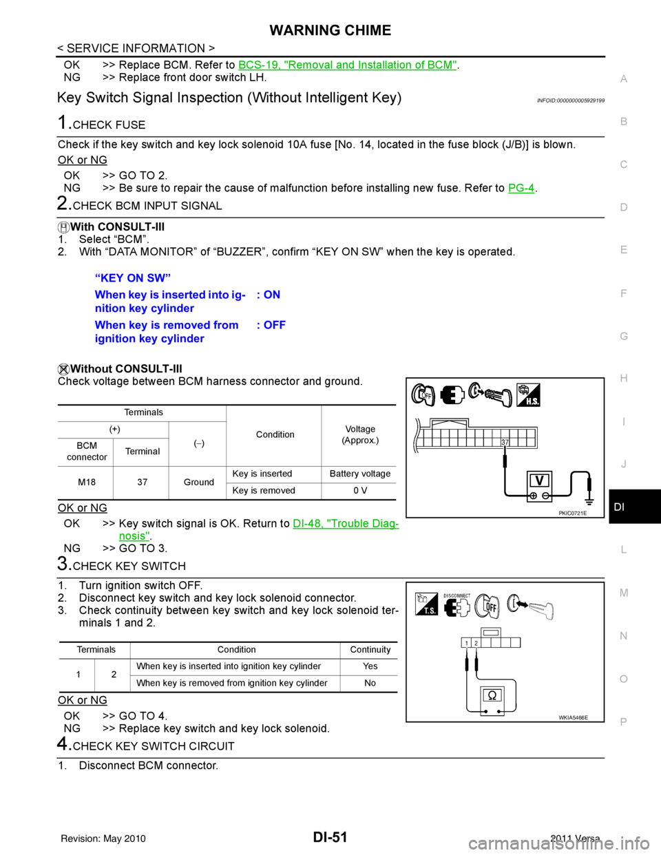
2.CHECK BCM INPUT SIGNAL
With CONSULT-III
1. Select “BCM”.
2. With “DATA MONITOR” of “BUZZER”, confirm “KEY ON SW” when the key is operated.
Without CONSULT-III
Check voltage between BCM harness connector and ground.
OK or NG
OK >> Key switch signal is OK. Return to DI-48, "Trouble Diag-
nosis".
NG >> GO TO 3.
3.CHECK KEY SWITCH
1. Turn ignition switch OFF.
2. Disconnect key switch and key lock solenoid connector.
3. Check continuity between key switch and key lock solenoid ter- minals 1 and 2.
OK or NG
OK >> GO TO 4.
NG >> Replace key switch and key lock solenoid.
4.CHECK KEY SWITCH CIRCUIT
1. Disconnect BCM connector. “KEY ON SW”
When key is inserted into ig-
nition key cylinder
: ON
When key is removed from
ignition key cylinder : OFF
Te r m i n a l s
ConditionVoltag e
(Approx.)
(+)
(−)
BCM
connector Te r m i n a l
M18 37 Ground Key is inserted Battery voltage
Key is removed
0 V
PKIC0721E
Terminals ConditionContinuity
12 When key is inserted into ignition key cylinder Yes
When key is removed from ignition key cylinder No
WKIA5466E
Revision: May 2010
2011 Versa
Page 1291 of 3787
DI-52
< SERVICE INFORMATION >
WARNING CHIME
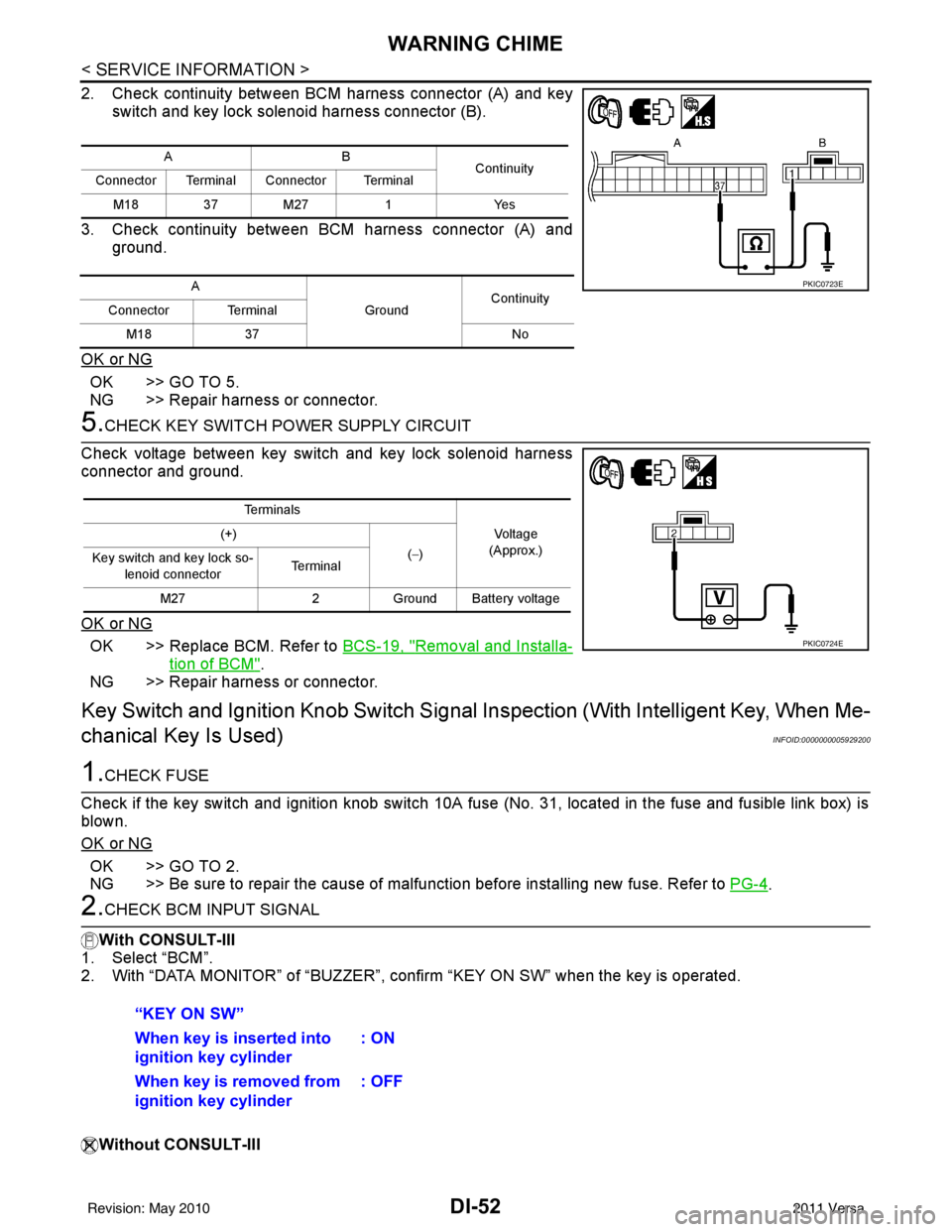
2. Check continuity between BCM harness connector (A) and keyswitch and key lock solenoid harness connector (B).
3. Check continuity between BCM harness connector (A) and ground.
OK or NG
OK >> GO TO 5.
NG >> Repair harness or connector.
5.CHECK KEY SWITCH PO WER SUPPLY CIRCUIT
Check voltage between key switch and key lock solenoid harness
connector and ground.
OK or NG
OK >> Replace BCM. Refer to BCS-19, "Removal and Installa-
tion of BCM".
NG >> Repair harness or connector.
Key Switch and Ignition Knob Switch Signal Inspection (With Intelligent Key, When Me-
chanical Key Is Used)
INFOID:0000000005929200
1.CHECK FUSE
Check if the key switch and ignition knob switch 10A fuse (No. 31, located in the fuse and fusible link box) is
blown.
OK or NG
OK >> GO TO 2.
NG >> Be sure to repair the cause of malfunction before installing new fuse. Refer to PG-4
.
2.CHECK BCM INPUT SIGNAL
With CONSULT-III
1. Select “BCM”.
2. With “DATA MONITOR” of “BUZZER”, c onfirm “KEY ON SW” when the key is operated.
Without CONSULT-III
AB Continuity
Connector Terminal Connector Terminal
M18 37 M27 1Yes
A GroundContinuity
Connector Terminal
M18 37 No
PKIC0723E
Te r m i n a l s
Voltage
(Approx.)
(+)
(−)
Key switch and key lock so-
lenoid connector Te r m i n a l
M27 2Ground Battery voltage
PKIC0724E
“KEY ON SW”
When key is inserted into
ignition key cylinder : ON
When key is removed from
ignition key cylinder : OFF
Revision: May 2010
2011 Versa
Page 1293 of 3787
DI-54
< SERVICE INFORMATION >
WARNING CHIME
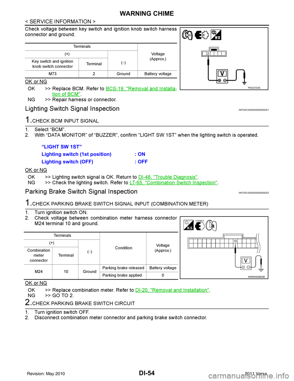
Check voltage between key switch and ignition knob switch harness
connector and ground.
OK or NG
OK >> Replace BCM. Refer to BCS-19, "Removal and Installa-
tion of BCM".
NG >> Repair harness or connector.
Lighting Switch Signal InspectionINFOID:0000000005929201
1.CHECK BCM INPUT SIGNAL
1. Select “BCM”.
2. With “DATA MONITOR” of “BUZZER”, confirm “LIG HT SW 1ST” when the lighting switch is operated.
OK or NG
OK >> Lighting switch signal is OK. Return to DI-48, "Trouble Diagnosis".
NG >> Check the lighting switch. Refer to LT-65, "
Combination Switch Inspection".
Parking Brake Switch Signal InspectionINFOID:0000000005929202
1.CHECK PARKING BRAKE SWITCH SIGNAL INPUT (COMBINATION METER)
1. Turn ignition switch ON.
2. Check voltage between combination meter harness connector M24 terminal 10 and ground.
OK or NG
OK >> Replace combination meter. Refer to DI-20, "Removal and Installation".
NG >> GO TO 2.
2.CHECK PARKING BRAKE SWITCH CIRCUIT
1. Turn ignition switch OFF.
2. Disconnect combination meter connector and parking brake switch connector.
Te r m i n a l s
Vo l ta g e
(Approx.)
(+)
(−)
Key switch and ignition
knob switch connector Te r m i n a l
M73 2Ground Battery voltage
PKIC0724E
“LIGHT SW 1ST”
Lighting switch ( 1st position) : ON
Lighting switch (OFF) : OFF
Te r m i n a l s
ConditionVoltag e
(Approx.)
(+)
(−)
Combination
meter
connector Te r m i n a l
M24 10 Ground Parking brake released Battery voltage
Parking brake applied 0
AWMIA0066GB
Revision: May 2010
2011 Versa