2011 NISSAN LATIO fuse chart
[x] Cancel search: fuse chartPage 463 of 3787
![NISSAN LATIO 2011 Service Repair Manual AV-66
< SERVICE INFORMATION >[AUDIO WITH NAVIGATION]
AUDIO
END ON-BOARD DIAGNOSIS
Turn OFF ignition switch.
Noise InspectionINFOID:0000000005931317
The vehicle itself can be a source of noise if noise NISSAN LATIO 2011 Service Repair Manual AV-66
< SERVICE INFORMATION >[AUDIO WITH NAVIGATION]
AUDIO
END ON-BOARD DIAGNOSIS
Turn OFF ignition switch.
Noise InspectionINFOID:0000000005931317
The vehicle itself can be a source of noise if noise](/manual-img/5/57357/w960_57357-462.png)
AV-66
< SERVICE INFORMATION >[AUDIO WITH NAVIGATION]
AUDIO
END ON-BOARD DIAGNOSIS
Turn OFF ignition switch.
Noise InspectionINFOID:0000000005931317
The vehicle itself can be a source of noise if noise
prevention parts or electrical equipment is malfunctioning.
Check if noise is caused and/or changed by engine speed, ignition switch turned to each position, and opera-
tion of each piece of electrical equipment, and determine the cause.
NOTE:
The source of the noise can be found easily by listening to the noise while removing the fuses of electrical
components, one by one.
TYPE OF NOISE AND POSSIBLE CAUSE
Symptom ChartINFOID:0000000006216708
MALFUNCTION WITH NAVIGATION
System configuration • 8 pulses speed
• Clock ON/OFF
• Equalizer setup X11C
• RF tuning
• Antenna type
• Sound system
• Sub Out: Code
• Steering wheel The device is configured by a connect-
ed hardware circuit.
The parameter is
influenced.
Self test •Bluetooth
® module Access Mal-
function
• SD-card Access Malfunction
• Radio-Antenna Circuit Malfunc-
tion
• GPS Antenna Circuit Malfunc-
tion
• Microphone Circuit Malfunction A system self test is executed: the re-
sult is stored into
the error memory
which is shown afterwards as a list of
codes of the detected malfunctions.
Mode
ItemContent
Occurrence condition Possible cause
Occurs only when engine is ON. A continuous growling noise occurs. The speed of
the noise varies with changes in the engine speed.
Ignition components
A whistling noise occurs while the engine speed is
high. A booming noise occurs while the engine is
running and the lighting switch is ON. Generator
Noise only occurs when various
electrical components are oper-
ating. A cracking or snapping sound occurs with the op-
eration of various switches.
Relay malfunction, radio malfunction
The noise occurs when various motors are operat-
ing. • Motor case ground
• Motor
The noise occurs constantly, not just under certain conditions. • Rear defogger coil malfunction
• Open circuit in printed heater
A cracking or snapping sound occurs while the vehicle is being driven, especially when
it is vibrating excessively. • Ground wire of body parts.
• Ground due to improper part installation
• Wiring connections or a short circuit
Symptoms
Check itemsProbable malfunction location / Action to
take
Display does not turn ON. All switches cannot be operated.
AV control unit power supply and ground
circuit. Refer to
AV- 6 9
.
All switches can be operated. AV control unit. Refer to AV- 6 9
.
Revision: May 2010 2011 Versa
Page 553 of 3787
POWER DOOR LOCK SYSTEMBL-43
< SERVICE INFORMATION >
C
DE
F
G H
J
K L
M A
B
BL
N
O P
Trouble Diagnosis Symptom ChartINFOID:0000000005929292
BCM Power Supply and Gr ound Circuit InspectionINFOID:0000000006215770
1.CHECK FUSES AND FUSIBLE LINK
• Check 40A fusible link (letter g , located in the fuse and fusible link box).
• Check 10A fuses [No. 6, 8 and 20, lo cated in the fuse block (J/B)].
OK or NG
OK >> GO TO 2.
NG >> If fuse is blown, be sure to eliminate cause of malfunction before installing new fuse. Refer to PG-
4, "Schematic" .
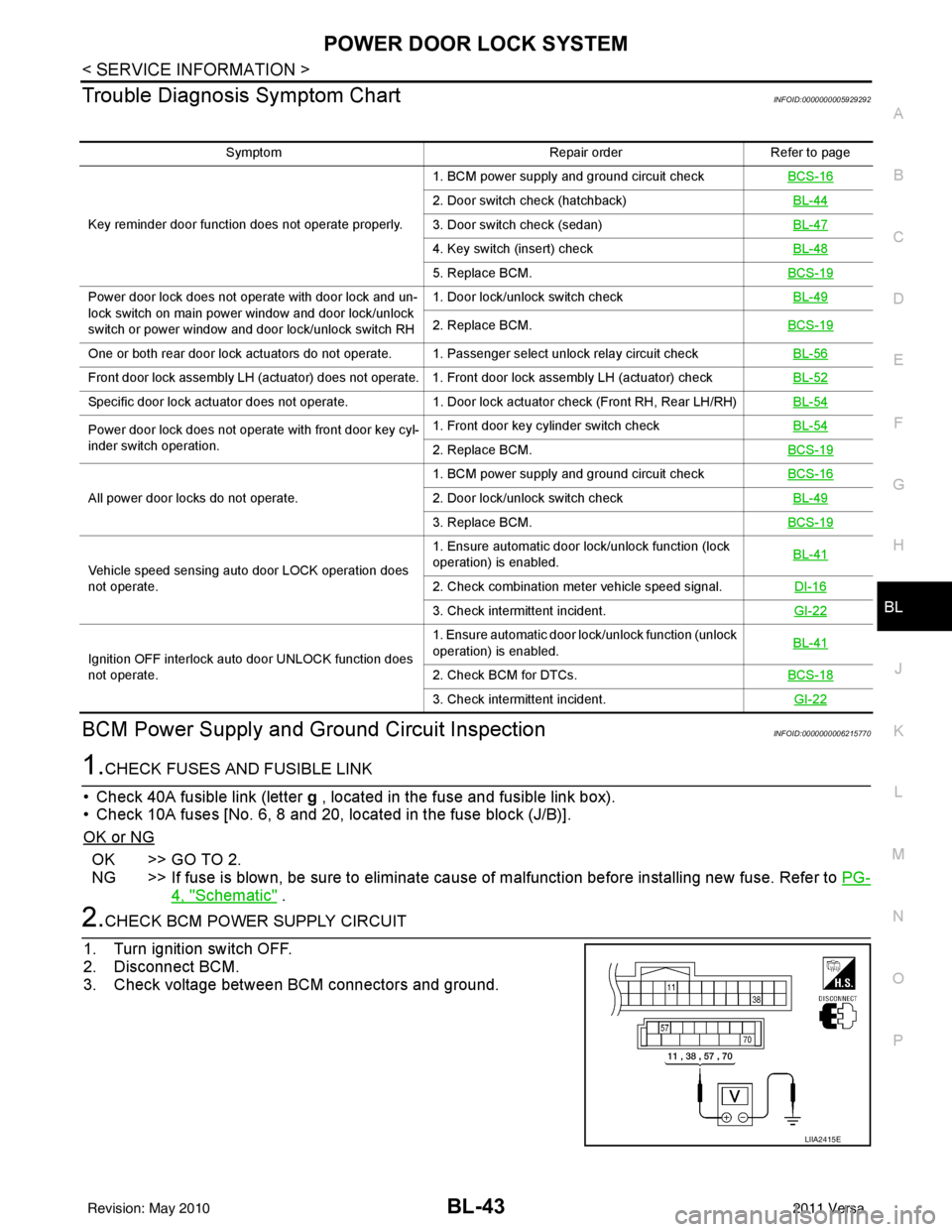
2.CHECK BCM POWER SUPPLY CIRCUIT
1. Turn ignition switch OFF.
2. Disconnect BCM.
3. Check voltage between BCM connectors and ground.
Symptom Repair orderRefer to page
Key reminder door function does not operate properly. 1. BCM power supply and ground circuit check
BCS-16
2. Door switch check (hatchback) BL-44
3. Door switch check (sedan)BL-47
4. Key switch (insert) checkBL-48
5. Replace BCM.BCS-19
Power door lock does not operate with door lock and un-
lock switch on main power window and door lock/unlock
switch or power window and door lock/unlock switch RH1. Door lock/unlock switch check
BL-49
2. Replace BCM.BCS-19
One or both rear door lock actuators do not operate. 1. Passenger select unlock relay circuit check BL-56
Front door lock assembly LH (actuator) does not operate. 1. Front door lock assembly LH (actuator) checkBL-52
Specific door lock actuator does not operate.1. Door lock actuator check (Front RH, Rear LH/RH) BL-54
Power door lock does not operate with front door key cyl-
inder switch operation.1. Front door key cylinder switch check
BL-54
2. Replace BCM.BCS-19
All power door locks do not operate.1. BCM power supply and ground circuit check
BCS-162. Door lock/unlock switch check BL-49
3. Replace BCM.BCS-19
Vehicle speed sensing auto door LOCK operation does
not operate.1. Ensure automatic door lock/unlock function (lock
operation) is enabled.
BL-41
2. Check combination meter vehicle speed signal.
DI-16
3. Check intermittent incident.GI-22
Ignition OFF interlock auto door UNLOCK function does
not operate.1. Ensure automatic door lock/unlock function (unlock
operation) is enabled.
BL-41
2. Check BCM for DTCs.
BCS-18
3. Check intermittent incident. GI-22
LIIA2415E
Revision: May 2010 2011 Versa
Page 693 of 3787
BACK DOOR LOCKBL-183
< SERVICE INFORMATION >
C
DE
F
G H
J
K L
M A
B
BL
N
O P
CONSULT-III APPLICATION ITEMS
Data Monitor
Active Test
Work FlowINFOID:0000000005929385
1. Check the symptom and customer's requests.
2. Understand the outline of system. Refer to BL-173, "
System Description".
3. Repair or replace any malfunctioning parts. Refer to BL-183, "
Trouble Diagnosis Chart by Symptom".
4. Does back door opener operate normally? If Yes, GO TO 5. If No, GO TO 3.
5. Inspection End.
Trouble Diagnosis Chart by SymptomINFOID:0000000005929386
BCM Power Supply and Gr ound Circuit InspectionINFOID:0000000006215774
1.CHECK FUSES AND FUSIBLE LINK
• Check 40A fusible link (letter g , located in the fuse and fusible link box).
• Check 10A fuses [No. 6, 8 and 20, lo cated in the fuse block (J/B)].
OK or NG
OK >> GO TO 2.
Monitor item Content
IGN ON SW Indicates [ON/OFF] condition of ignition switch.
TRNK OPNR SW Indicates [ON/OFF] condition of back door open signal from back door opener switch.
VEHICLE SPEED Indicates [km/h] condition of vehicle speed.
Test item Content
TRUNK/BACK DOOR This test checks back door lock assembly operation.
Back door opens when “Open” is selected.
Symptom
Diagnoses/service procedureReference
page
Back door opener does not operate.
(Without Intelligent Key or power windows) 1. Check BCM power supply and ground circuit.
BCS-16
2. Check back door opener switch circuit. BL-184
3. Check back door lock assembly (actuator) circuit.BL-191
4. Replace BCM.BCS-19
Back door opener does not operate.
(Without Intelligent Key, with power windows)1. Check BCM power supply and ground circuit.
BCS-162. Check back door opener switch circuit. BL-187
3. Check back door lock assembly (actuator) circuit.BL-191
4. Replace BCM.BCS-19
Back door opener does not operate.
(With Intelligent Key)1. Check BCM power supply and ground circuit.
BCS-16
2.Check Intelligent Key power supply and ground cir-
cuit.
BL-126
3. Check back door opener switch circuit.
BL-189
4. Check back door lock assembly (actuator) circuit.BL-191
5. Replace BCM.BCS-19
Revision: May 2010 2011 Versa
Page 718 of 3787
BL-208
< SERVICE INFORMATION >
TRUNK LID OPENER
CONSULT-III APPLICATION ITEMS
Data Monitor
Active Test
Work FlowINFOID:0000000005929403
1. Check the symptom and customer's requests.
2. Understand the outline of system. Refer to BL-198, "
System Description".
3. Repair or replace any malfunctioning parts. Refer to BL-208, "
Trouble Diagnosis Chart by Symptom".
4. Does trunk lid opener operate normally? If Yes, GO TO 5. If No, GO TO 3.
5. Inspection End.
Trouble Diagnosis Chart by SymptomINFOID:0000000005929404
BCM Power Supply and Ground Circuit InspectionINFOID:0000000006215777
1.CHECK FUSES AND FUSIBLE LINK
• Check 40A fusible link (letter g , located in the fuse and fusible link box).
• Check 10A fuses [No. 6, 8 and 20, lo cated in the fuse block (J/B)].
OK or NG
OK >> GO TO 2.
Monitor item Content
IGN ON SW Indicates [ON/OFF] condition of ignition switch.
TRNK OPNR SW Indicates [ON/OFF] condition of trun k open signal from trunk lid opener switch.
VEHICLE SPEED Indicates [km/h] condition of vehicle speed.
Test item Content
TRUNK/BACK DOOR This test checks trunk release solenoid operation.
Trunk opens when “Open” is selected.
Symptom
Diagnoses/service procedureReference
page
Trunk lid opener does not operate.
(Without Intelligent Key or power windows) 1. Check BCM power supply and ground circuit.
BCS-16
2. Check trunk lid opener switch circuit. BL-209
3. Check trunk lid lock assembly (actuator) circuit.BL-214
4. Replace BCM.BCS-19
Trunk lid opener does not operate.
(Without Intelligent Key, with power windows)1. Check BCM power supply and ground circuit.
BCS-162. Check trunk lid opener switch circuit. BL-209
3. Check trunk lid lock assembly (actuator) circuit.BL-214
4. Replace BCM.BCS-19
Trunk lid opener does not operate.
(With Intelligent Key)1. Check BCM power supply and ground circuit.
BCS-16
2.Check Intelligent Key power supply and ground cir-
cuit.
BL-126
3. Check trunk lid opener switch circuit.
BL-212
4. Check trunk lid lock assembly (actuator) circuit.BL-214
5. Replace BCM.BCS-19
Revision: May 2010 2011 Versa
Page 768 of 3787
BL-258
< SERVICE INFORMATION >
NATS (NISSAN ANTI-THEFT SYSTEM)
Self-diagnosis related item
• *: When NATS detects trouble, the security indicator lights up while ignition key is in the “ON” position.
SYMPTOM MATRIX CHART 2
Non self-diagnosis related item
*: CONSULT-III self-diagnostic results display screen “no malfunction is detected”.
Diagnosis Procedure 1INFOID:0000000005929440
Self-diagnostic results:
“CHAIN OF ECM-IMMU” displayed on CONSULT-III screen
First perform the “SELF-DIAG RESU LTS” in “BCM” with CONSULT-III, then perform the trouble diag-
nosis of malfunction system indicated “SELF-DIAG RESULTS” of “BCM”. Refer to BCS-18, "
CAN Com-
munication Inspection Using CONSULT-III (Self-Diagnosis)" .
SYMPTOMDisplayed “SELF-DIAG
RESULTS” on CON- SULT-III screen. DIAGNOSTIC PROCE-
DURE
(Reference page) SYSTEM
(Malfunctioning part or mode)
• Security indicator lighting up*
• Engine cannot be started CHAIN OF ECM-IMMU
[P1612] PROCEDURE 1
(BL-258
) In rare case, “CHAIN OF ECM-IMMU” might be stored
during key registration procedure, even if the system is
not malfunctioning.
Open circuit in battery voltage line of BCM circuit
Open circuit in ignition line of BCM circuit
Open circuit in ground line of BCM circuit
Open or short circuit between BCM and ECM commu-
nication line
ECM
BCM
DIFFERENCE OF KEY [P1615] PROCEDURE 6
(BL-264
) Unregistered ignition key is used.
BCM is malfunctioning.
CHAIN OF IMMU-KEY [P1614] PROCEDURE 2
(BL-260
) Malfunction of key ID chip
Communication line between ANT/ AMP and BCM:
Open circuit or short circuit of battery voltage line or
ground line
Open circuit in power source line of ANT/ AMP circuit
Open circuit in ground line of ANT/ AMP circuit
NATS antenna amp.
BCM
ID DISCORD, IMM- ECM
[P1611] PROCEDURE 3
(BL-261
) System initialization has not yet been completed.
ECM
LOCK MODE [P1610] PROCEDURE 5
(BL-263
) When the starting operation is carried out five or more
times consecutively under the following conditions,
NATS will shift the mode to one which prevents the en-
gine from being started.
• Unregistered ignition key is used.
• BCM or ECM’s malfunctioning.
Security indicator
lighting up* DON'T ERASE BE-
FORE CHECKING ENG DIAG WORK FLOW
(BL-255
) Engine trouble data and NATS trouble data have been
detected in ECM
SYMPTOM
DIAGNOSTIC PROCEDURE
(Reference page) SYSTEM
(Malfunctioning part or mode)
Security indicator does not light up*. PROCEDURE 4
(BL-262
) Security indictor.
Open circuit between Fuse and BCM
BCM
Revision: May 2010
2011 Versa
Page 1254 of 3787
COMBINATION METERSDI-15
< SERVICE INFORMATION >
C
DE
F
G H
I
J
L
M A
B
DI
N
O P
YES >> GO TO 2.
NO >> Check power supply and ground circuit of combination meter. Refer to DI-15, "
Power Supply and
Ground Circuit Inspection" .
2.CHECK COMBINATION METER (CONSULT-III)
Select “METER/M&A” on CONSULT-II I and perform self-diagnosis of combination meter. Refer to DI-13,
"CONSULT-III Function (METER/M&A)" .
Self
-diagnostic results content
No malfunction detected>> Refer to DI-15, "Symptom Chart" .
Malfunction detected>> Refer to DI-13, "
CONSULT-III Function (METER/M&A)" .
Symptom ChartINFOID:0000000005929169
Power Supply and Gro und Circuit InspectionINFOID:0000000005929170
1.CHECK FUSE
Check for blown combination meter fuses.
OK or NG
OK >> GO TO 2.
NG >> Be sure to eliminate cause of malfunction before installing new fuse. Refer to PG-4
.
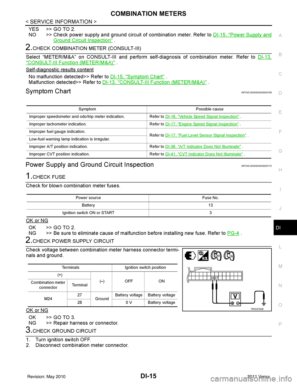
2.CHECK POWER SUPPLY CIRCUIT
Check voltage between combination meter harness connector termi-
nals and ground.
OK or NG
OK >> GO TO 3.
NG >> Repair harness or connector.
3.CHECK GROUND CIRCUIT
1. Turn ignition switch OFF.
2. Disconnect combination meter connector.
Symptom Possible cause
Improper speedometer and odo/trip meter indication. Refer to DI-16, "
Vehicle Speed Signal Inspection" .
Improper tachometer indication. Refer to DI-17, "
Engine Speed Signal Inspection" .
Improper fuel gauge indication. Refer to DI-17, "
Fuel Level Sensor Signal Inspection" .
Low-fuel warning lamp indication is irregular.
Improper A/T position indication. Refer to DI-36, "
A/T Indicator Does Not Illuminate" .
Improper CVT position indication. Refer to DI-41, "
CVT Indicator Does Not Illuminate" .
Power source Fuse No.
Battery 13
Ignition switch ON or START 3
TerminalsIgnition switch position
(+) (–) OFF ON
Combination meter
connector Te r m i n a l
M24 27
Ground Battery voltage Battery voltage
28 0 V Battery voltage
PKIC0700E
Revision: May 2010 2011 Versa
Page 2721 of 3787
HOW TO USE THIS MANUALGI-17
< SERVICE INFORMATION >
C
DE
F
G H
I
J
K L
M B
GI
N
O P
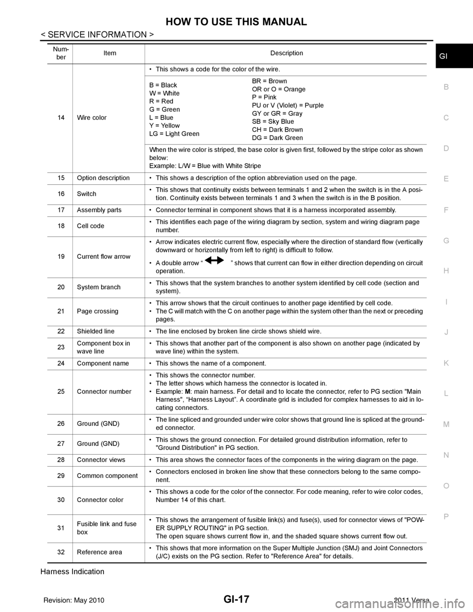
Harness Indication
14 Wire color • This shows a code for the color of the wire.
B = Black
W = White
R = Red
G = Green
L = Blue
Y = Yellow
LG = Light Green BR = Brown
OR or O = Orange
P = Pink
PU or V (Violet) = Purple
GY or GR = Gray
SB = Sky Blue
CH = Dark Brown
DG = Dark Green
When the wire color is striped, the base color is given first, followed by the stripe color as shown
below:
Example: L/W = Blue with White Stripe
15 Option description • This shows a description of the option abbreviation used on the page.
16 Switch • This shows that continuity exists between terminals 1 and 2 when the switch is in the A posi-
tion. Continuity exists between terminals 1 and 3 when the switch is in the B position.
17 Assembly parts • Connector terminal in component shows that it is a harness incorporated assembly.
18 Cell code • This identifies each page of the wiring diagram by section, system and wiring diagram page
number.
19 Current flow arrow • Arrow indicates electric current flow, especially where the direction of standard flow (vertically
downward or horizontally from left to right) is difficult to follow.
• A double arrow “ ” shows that current can flow in either direction depending on circuit operation.
20 System branch • This shows that the system branches to another system identified by cell code (section and
system).
21 Page crossing • This arrow shows that the circuit continues to another page identified by cell code.
• The C will match with the C on another page within the system other than the next or preceding
pages.
22 Shielded line • The line enclosed by broken line circle shows shield wire.
23 Component box in
wave line • This shows that another part of the component is also shown on another page (indicated by
wave line) within the system.
24 Component name • This shows the name of a component.
25 Connector number • This shows the connector number.
• The letter shows which harness the connector is located in.
•Example:
M: main harness. For detail and to locate the connector, refer to PG section "Main
Harness", “Harness Layout”. A coordinate grid is included for complex harnesses to aid in lo-
cating connectors.
26 Ground (GND) • The line spliced and grounded under wire color shows that ground line is spliced at the ground-
ed connector.
27 Ground (GND) • This shows the ground connection. For detailed ground distribution information, refer to
"Ground Distribution" in PG section.
28 Connector views • This area shows the connector faces of the components in the wiring diagram on the page.
29 Common component • Connectors enclosed in broken line show that these connectors belong to the same compo-
nent.
30 Connector color • This shows a code for the color of the connector. For code meaning, refer to wire color codes,
Number 14 of this chart.
31 Fusible link and fuse
box • This shows the arrangement of fusible link(s) and fuse(s), used for connector views of "POW-
ER SUPPLY ROUTING" in PG section.
The open square shows current flow in, and the shaded square shows current flow out.
32 Reference area • This shows that more information on the Super Multiple Junction (SMJ) and Joint Connectors
(J/C) exists on the PG section. Refer to "Reference Area" for details.
Num-
ber Item
Description
Revision: May 2010 2011 Versa
Page 2785 of 3787
POWER WINDOW SYSTEMGW-31
< SERVICE INFORMATION >
C
DE
F
G H
J
K L
M A
B
GW
N
O P
WORK SUPPORT
DATA MONITOR
Power Window Auto Operation InitializationINFOID:0000000005929478
1. Turn the ignition switch ON.
2. Open the window—all the way DOWN.
3. Pull all the way UP on the switch and hold (close the window). • Continue holding the switch all the way UP for 4 seconds after the window is closed.
4. Confirm the window is now operating correctly. NOTE:
• If the window is still not operating correctly, refer to GW-31, "
Trouble Diagnosis Symptom Chart".
• The above initialization procedure must be performed if any of the following occur:
- Battery cable is disconnected
- Power window switch connector is disconnected
- Power window regulator is replaced
- Power window motor is replaced
- Window glass is removed
- Window glass run rubber is replaced
- Power window fuse is blown
- Window is partly opened and/or closed many times without being fully closed.
Trouble Diagnosis Symptom ChartINFOID:0000000005929479
Check that other systems us ing the signal of the following systems operate normally.
Test Item Description
RETAINED PWR This test is able to supply RAP signal (powe
r) from BCM (body control module) to power window
system and power sunroof system (if equipped). Those systems can be operated when turning on
“RETAINED PWR” on CONSULT-III screen even if the ignition switch is turned OFF.
NOTE:
During this test, CONSULT-III can be operated with ignition switch in OFF position. “RETAINED
PWR” should be turned “ON” or “OFF” on CONSULT-III screen when ignition switch is ON. Then
turn ignition switch OFF to check retained power operation. CONSULT-III might be stuck if “RE-
TAINED PWR” is turned “ON” or “OFF” on CONSULT-III screen when ignition switch is OFF.
Work item Description
RETAINED PWR RAP signal’s power supply period can be changed by mode setting. Selects RAP signal’s power
supply period between three steps
• MODE1 (45 sec.)/MODE2 (OFF)/MODE3 (2 min.).
Work item
Description
IGN ON SW Indicates (ON/OFF) condition of ignition switch
DOOR SW-DR Indicates (ON/OFF) condition of front door switch LH
DOOR SW-AS Indicates (ON/OFF) condition of front door switch RH
Symptom Repair orderRefer to page
None of the power windows can be operated using any switch 1. BCM power supply and ground circuit check
BCS-16
2. Main power window and door lock/unlock
power supply and ground circuit check GW-32
3. Replace main power window and door lock/
unlock switch
EI-36
Front power window LH alone does not operate 1. Front power window motor LH circuit check
GW-332. Replace main power window and door lock/
unlock switch EI-36
Revision: May 2010
2011 Versa