2011 NISSAN LATIO ignition
[x] Cancel search: ignitionPage 199 of 3787
AT-182
< SERVICE INFORMATION >
TROUBLE DIAGNOSIS FOR SYMPTOMS
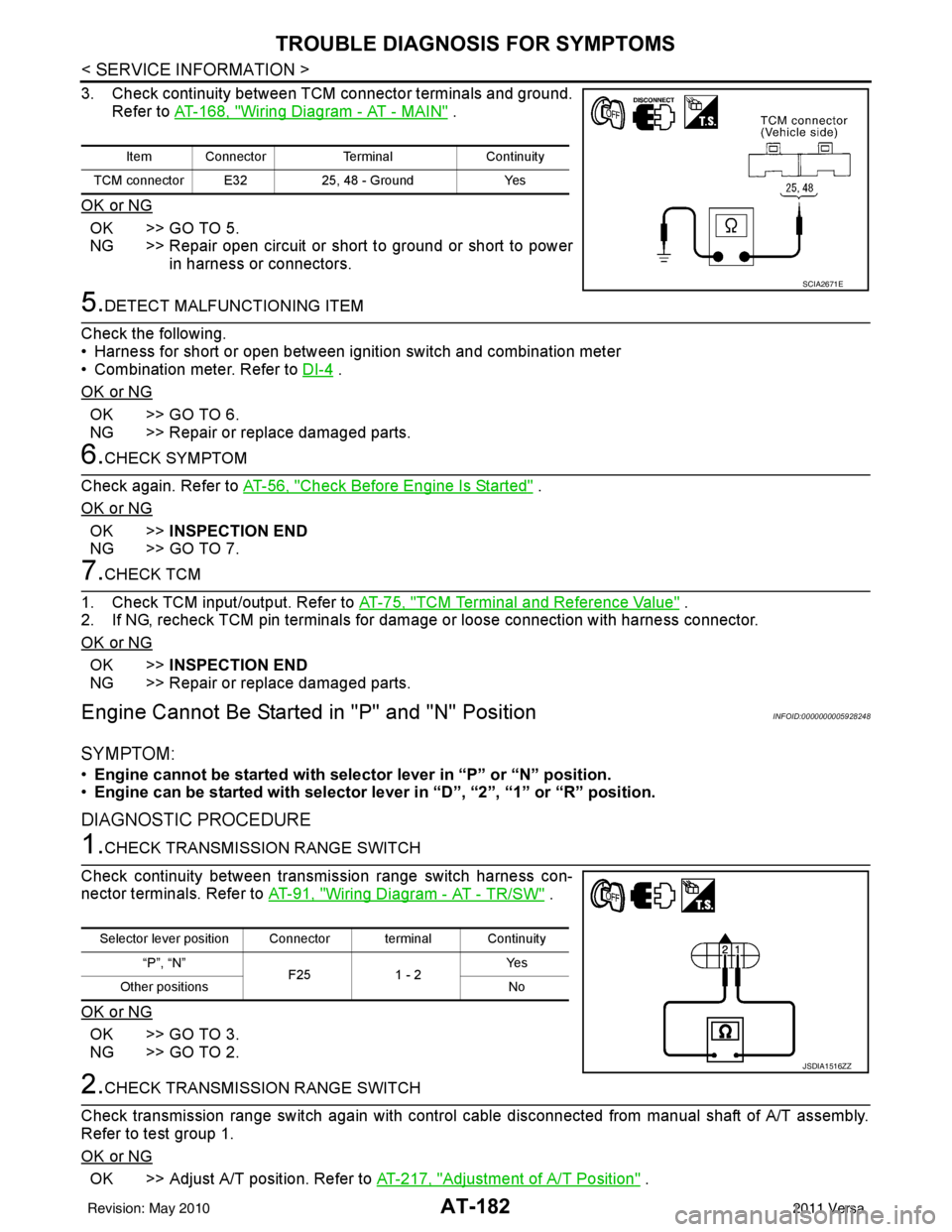
3. Check continuity between TCM connector terminals and ground.Refer to AT-168, "
Wiring Diagram - AT - MAIN" .
OK or NG
OK >> GO TO 5.
NG >> Repair open circuit or short to ground or short to power in harness or connectors.
5.DETECT MALFUNCTIONING ITEM
Check the following.
• Harness for short or open between ignition switch and combination meter
• Combination meter. Refer to DI-4
.
OK or NG
OK >> GO TO 6.
NG >> Repair or replace damaged parts.
6.CHECK SYMPTOM
Check again. Refer to AT-56, "
Check Before Engine Is Started" .
OK or NG
OK >> INSPECTION END
NG >> GO TO 7.
7.CHECK TCM
1. Check TCM input/output. Refer to AT-75, "
TCM Terminal and Reference Value" .
2. If NG, recheck TCM pin terminals for damage or loose connection with harness connector.
OK or NG
OK >> INSPECTION END
NG >> Repair or replace damaged parts.
Engine Cannot Be Started in "P" and "N" PositionINFOID:0000000005928248
SYMPTOM:
•Engine cannot be started with select or lever in “P” or “N” position.
• Engine can be started with selector lever in “D”, “2”, “1” or “R” position.
DIAGNOSTIC PROCEDURE
1.CHECK TRANSMISSION RANGE SWITCH
Check continuity between transmission range switch harness con-
nector terminals. Refer to AT-91, "
Wiring Diagram - AT - TR/SW" .
OK or NG
OK >> GO TO 3.
NG >> GO TO 2.
2.CHECK TRANSMISSION RANGE SWITCH
Check transmission range switch again with control cabl e disconnected from manual shaft of A/T assembly.
Refer to test group 1.
OK or NG
OK >> Adjust A/T position. Refer to AT-217, "Adjustment of A/T Position" .
Item ConnectorTerminalContinuity
TCM connector E32 25, 48 - GroundYes
SCIA2671E
Selector lever position Connector terminal Continuity
“P”, “N” F251 - 2 Ye s
Other positions No
JSDIA1516ZZ
Revision: May 2010 2011 Versa
Page 214 of 3787
TROUBLE DIAGNOSIS FOR SYMPTOMSAT-197
< SERVICE INFORMATION >
DE
F
G H
I
J
K L
M A
B
AT
N
O P
OK or NG
OK >> GO TO 6.
NG >> Repair or replace damaged parts.
6.CHECK SYMPTOM
Check again. Refer to AT-58, "
Cruise Test - Part 1" .
OK or NG
OK >> INSPECTION END
NG >> GO TO 7.
7.CHECK TCM
1. Check TCM input/output signals. Refer to AT-75, "
TCM Terminal and Reference Value" .
2. If NG, recheck TCM pin terminals for dam age or loose connection with harness connector.
OK or NG
OK >> INSPECTION END
NG >> Repair or replace damaged parts.
A/T Does Not Shift: D4→ D3, When OD OFFINFOID:0000000005928262
SYMPTOM:
A/T does not shift from D4 to D3 when OD OFF (OD OFF indicator lamp is on) on “Cruise Test — Part
3”.
DIAGNOSTIC PROCEDURE
1.CHECK CAN COMMUNICATION LINE
Perform self-diagnosis. Refer to AT-77, "
CONSULT-III Function (TRANSMISSION)" or AT-82, "Diagnosis Pro-
cedure without CONSULT-III" .
Is a malfunction in CAN communication indicated in the results?
YES >> Check CAN communication line. Refer to AT- 8 7 .
NO >> GO TO 2.
2.CHECK OVERDRIVE CO NTROL SWITCH CIRCUIT
With CONSULT-III
1. Turn ignition switch ON. (Do not start engine)
2. Select “TCM INPUT SIGNALS” in “DATA MONI TOR” mode for “TRANSMISSION” with CONSULT-III.
3. Read out “OVERDRIVE SW”. Check the signal of the overdrive control switch is indicated properly.
Without CONSULT-III
1. Turn ignition switch ON. (Do not start engine)
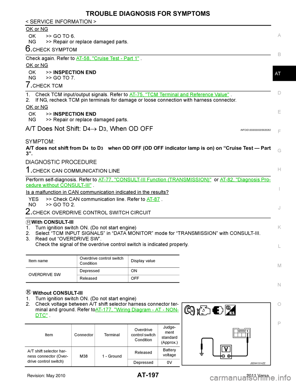
2. Check voltage between A/T shift selector harness connector ter- minal and ground. Refer to AT-177, "
Wiring Diagram - AT - NON-
DTC" .
Item name Overdrive control switch
ConditionDisplay value
OVERDRIVE SW Depressed
ON
Released OFF
ItemConnector Terminal Overdrive
control switch Condition Judge-
ment
standard
(Approx.)
A/T shift selector har-
ness connector (Over-
drive control switch) M38 1 - Ground
Released
Battery
voltage
Depressed 0V
JSDIA1514ZZ
Revision: May 2010 2011 Versa
Page 215 of 3787
AT-198
< SERVICE INFORMATION >
TROUBLE DIAGNOSIS FOR SYMPTOMS
OK or NG
OK >> Go to AT-190, "A/T Does Not Shift: D2→ D3" .
NG >> Check overdrive control switch. Refer to AT-175, "
Component Inspection" .
A/T Does Not Shift: D3→ 22, When Selector Lever "D" → "2" PositionINFOID:0000000005928263
SYMPTOM:
A/T does not shift from D3 to 22 when changing selector lever from “D” to “2” position on “Cruise
Test — Part 3”.
DIAGNOSTIC PROCEDURE
1.CHECK SYMPTOM
Check symptom. Refer to AT-58, "
Cruise Test - Part 1" or AT-61, "Cruise Test - Part 2" .
Is
“A/T Does Not Shift: D1 → D2 or Does Not Kickdown: D4→ D2” OK?
YES (With CONSULT-III) >>GO TO 2.
YES (Without CONSULT-III) >>GO TO 3.
NO >> Go to AT-189, "
A/T Does Not Shift: D1→ D2or Does Not Kickdown: D4→ D2" .
2.CHECK TRANSMISSION RANGE SWITCH CIRCUIT
With CONSULT-III
1. Turn ignition switch ON. (Do not start engine.)
2. Select “TCM INPUT SIGNALS” in “DATA MONITOR” mode for “TRANSMISSION” with CONSULT-III.
3. Read out “P·N”, “R”, “D”, “2” and “1” position switches moving selector lever to each position.
OK or NG
OK >> INSPECTION END
NG >> Check transmission range switch. Refer to AT-175, "
Component Inspection" .
3.CHECK TRANSMISSION RANGE SWITCH CIRCUIT
Without CONSULT-III
1. Turn ignition switch ON. (Do not start engine.)
Monitor item Condition Display value
PN POSI SW When setting selector le
ver to “N” or “P” posi-
tion. ON
When setting selector lever to other positions. OFF
R POSITION SW When setting selector lever to “R” position. ON
When setting selector lever to other positions. OFF
D POSITION SW When setting selector lever to “D” positions. ON
When setting selector lever to other positions. OFF
2 POSITION SW When setting selector lever to “2” position. ON
When setting selector lever to other positions. OFF
1 POSITION SW When setting selector lever to “1” position. ON
When setting selector lever to other positions. OFF
Revision: May 2010
2011 Versa
Page 216 of 3787
TROUBLE DIAGNOSIS FOR SYMPTOMSAT-199
< SERVICE INFORMATION >
DE
F
G H
I
J
K L
M A
B
AT
N
O P
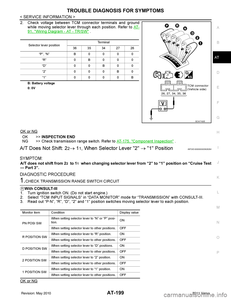
2. Check voltage between TCM connector terminals and ground while moving selector lever through each position. Refer to AT-
91, "Wiring Diagram - AT - TR/SW" .
B: Battery voltage
0: 0V
OK or NG
OK >>INSPECTION END
NG >> Check transmission range switch. Refer to AT-175, "
Component Inspection" .
A/T Does Not Shift: 22→ 11, When Selector Lever "2" → "1" PositionINFOID:0000000005928264
SYMPTOM:
A/T does not shift from 22 to 11 when changing selector lever from “2” to “1” position on “Cruise Test
— Part 3”.
DIAGNOSTIC PROCEDURE
1.CHECK TRANSMISSION RANGE SWITCH CIRCUIT
With CONSULT-III
1. Turn ignition switch ON. (Do not start engine.)
2. Select “TCM INPUT SIGNALS” in “DATA MONI TOR” mode for “TRANSMISSION” with CONSULT-III.
3. Read out “P·N”, “R”, “D”, “2” and “1” position switches moving selector lever to each position.
OK or NG
Selector lever position Te r m i n a l
36 35 34 27 26
“P”, “N” B 0 0 0 0
“R” 0B000
“D” 0 0 B 0 0
“2” 0 0 0 B 0
“1” 0 0 0 0 B
SCIA7162E
Monitor item Condition Display value
PN POSI SW When setting selector le
ver to “N” or “P” posi-
tion. ON
When setting selector lever to other positions. OFF
R POSITION SW When setting selector lever to “R” position. ON
When setting selector lever to other positions. OFF
D POSITION SW When setting selector lever to “D” positions. ON
When setting selector lever to other positions. OFF
2 POSITION SW When setting selector lever to “2” position. ON
When setting selector lever to other positions. OFF
1 POSITION SW When setting selector lever to “1” position. ON
When setting selector lever to other positions. OFF
Revision: May 2010
2011 Versa
Page 217 of 3787

AT-200
< SERVICE INFORMATION >
TROUBLE DIAGNOSIS FOR SYMPTOMS
OK >> GO TO 3
NG >> Check transmission range switch. Refer to AT-175, "
Component Inspection" .
2.CHECK TRANSMISSION RANGE SWITCH CIRCUIT
Without CONSULT-III
1. Turn ignition switch ON. (Do not start engine.)
2. Check voltage between TCM connector terminals and ground
while moving selector lever through each position. Refer to AT-
91, "Wiring Diagram - AT - TR/SW" .
B: Battery voltage
0: 0V
OK or NG
OK >> GO TO 3
NG >> Check transmission range switch. Refer to AT-175, "
Component Inspection" .
3.CHECK A/T POSITION
Check A/T position. Refer to AT-217, "
Checking of A/T Position" .
OK or NG
OK >> GO TO 4.
NG >> Adjust A/T position. Refer to AT-217, "
Adjustment of A/T Position" .
4.CHECK OUTPUT SPEED SENSOR AND VEHICLE SPEED SIGNAL CIRCUIT
Check output speed sensor and vehicle speed signal circuit. Refer to AT-100
and/or AT-153 .
OK or NG
OK >> GO TO 5.
NG >> Repair or replace output speed sens or and/or vehicle speed signal circuits.
5.CHECK A/T FLUID CONDITION
1. Remove oil pan. Refer to AT-237, "
Component" .
2. Check A/T fluid condition. Refer to AT-51, "
Inspections Before Trouble Diagnosis" .
OK or NG
OK >> GO TO 7.
NG >> GO TO 6.
6.DETECT MALFUNCTIONING ITEM
1. Remove control valve assembly. Refer to AT-222, "
Control Valve Assembly and Accumulators" .
2. Check the following items:
- Shift valve A
- Shift solenoid valve A
Selector lever position Te r m i n a l
36 35 34 27 26
“P”, “N” B0000 “R” 0B000
“D” 0 0 B 0 0
“2” 000B0
“1” 0000B
SCIA7162E
Revision: May 2010 2011 Versa
Page 218 of 3787
TROUBLE DIAGNOSIS FOR SYMPTOMSAT-201
< SERVICE INFORMATION >
DE
F
G H
I
J
K L
M A
B
AT
N
O P
- Overrun clutch control valve
- Overrun clutch solenoid valve
3. Disassemble A/T. Refer to AT-257, "
Disassembly" .
4. Check the following items:
- Servo piston assembly
- Brake band
OK or NG
OK >> GO TO 7.
NG >> Repair or replace damaged parts.
7.CHECK SYMPTOM
Check again. Refer to AT-62, "
Cruise Test - Part 3" .
OK or NG
OK >> INSPECTION END
NG >> GO TO 8.
8.CHECK TCM
1. Check TCM input/output signals. Refer to AT-75, "
TCM Terminal and Reference Value" .
2. If NG, recheck TCM pin terminals for dam age or loose connection with harness connector.
OK or NG
OK >> INSPECTION END
NG >> Repair or replace damaged parts.
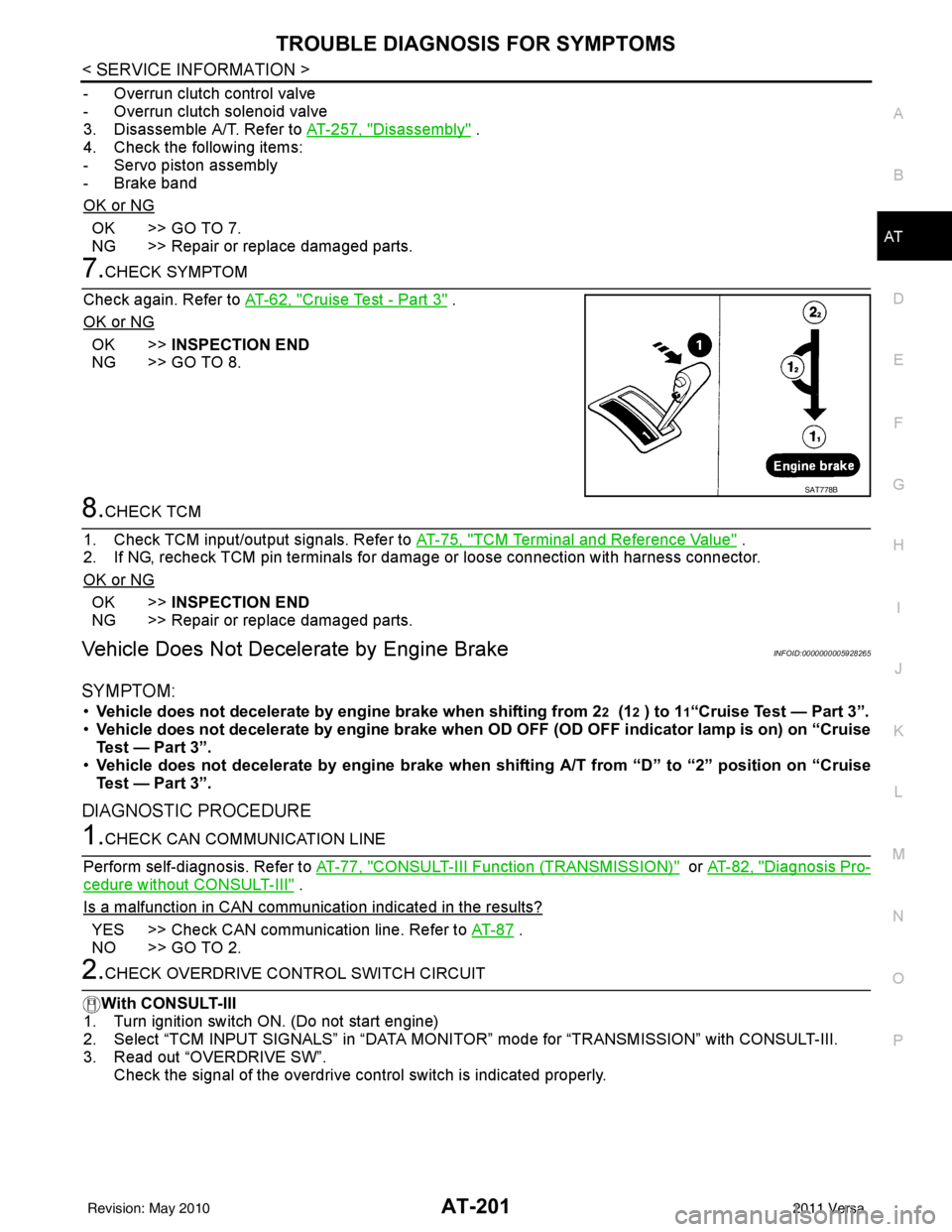
Vehicle Does Not Decelerate by Engine BrakeINFOID:0000000005928265
SYMPTOM:
• Vehicle does not decelerate by engine brake when shifting from 22 (12 ) to 11“Cruise Test — Part 3”.
• Vehicle does not decelerate by engi ne brake when OD OFF (OD OFF indicator lamp is on) on “Cruise
Test — Part 3”.
• Vehicle does not decelerate by engi ne brake when shifting A/T from “D” to “2” position on “Cruise
Test — Part 3”.
DIAGNOSTIC PROCEDURE
1.CHECK CAN COMMUNICATION LINE
Perform self-diagnosis. Refer to AT-77, "
CONSULT-III Function (TRANSMISSION)" or AT-82, "Diagnosis Pro-
cedure without CONSULT-III" .
Is a malfunction in CAN communication indicated in the results?
YES >> Check CAN communication line. Refer to AT- 8 7 .
NO >> GO TO 2.
2.CHECK OVERDRIVE CO NTROL SWITCH CIRCUIT
With CONSULT-III
1. Turn ignition switch ON. (Do not start engine)
2. Select “TCM INPUT SIGNALS” in “DATA MONI TOR” mode for “TRANSMISSION” with CONSULT-III.
3. Read out “OVERDRIVE SW”.
Check the signal of the overdrive control switch is indicated properly.
SAT778B
Revision: May 2010 2011 Versa
Page 219 of 3787
AT-202
< SERVICE INFORMATION >
TROUBLE DIAGNOSIS FOR SYMPTOMS
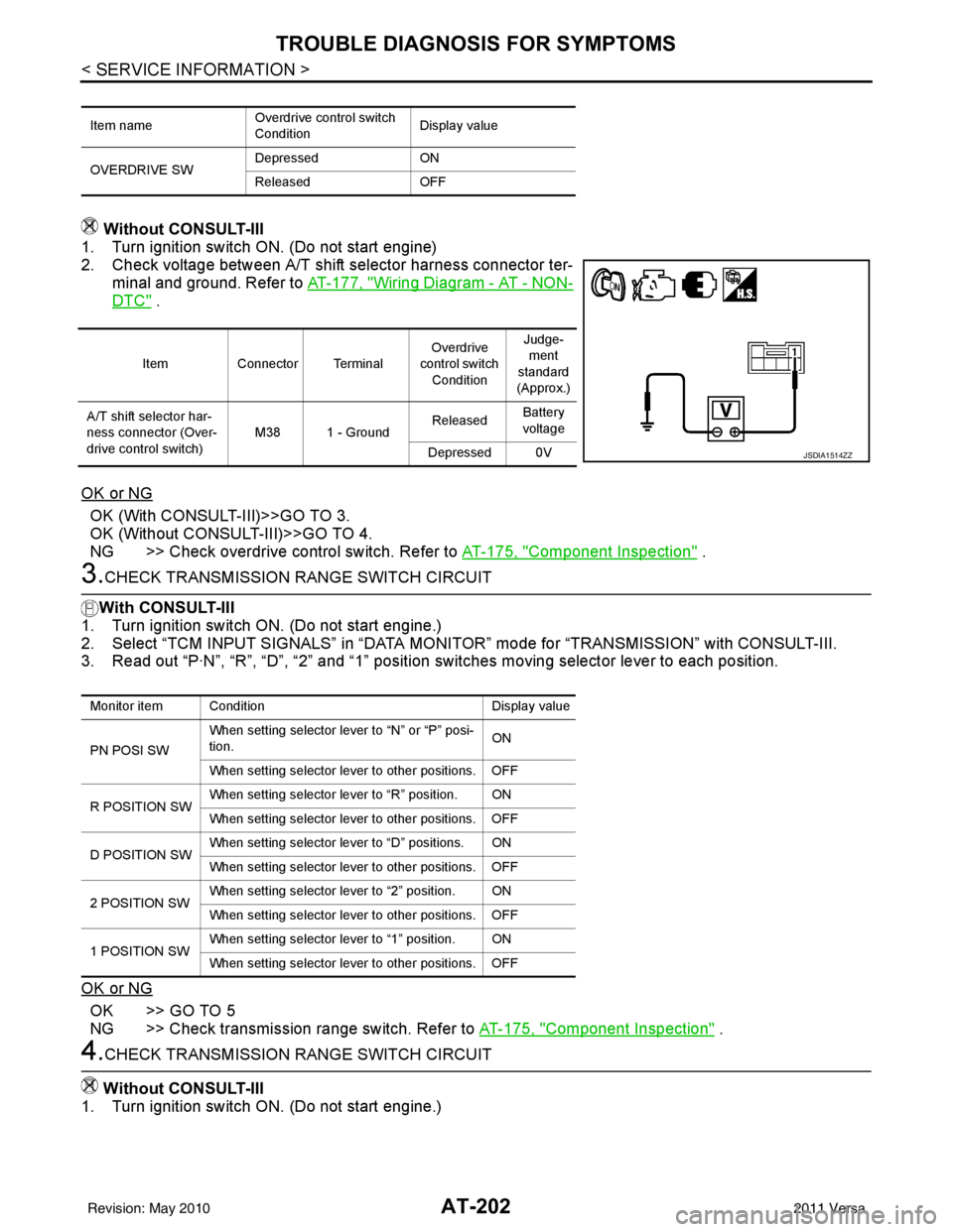
Without CONSULT-III
1. Turn ignition switch ON. (Do not start engine)
2. Check voltage between A/T shift selector harness connector ter-
minal and ground. Refer to AT-177, "
Wiring Diagram - AT - NON-
DTC" .
OK or NG
OK (With CONSULT-III)>>GO TO 3.
OK (Without CONSULT-III)>>GO TO 4.
NG >> Check overdrive control switch. Refer to AT-175, "
Component Inspection" .
3.CHECK TRANSMISSION RANGE SWITCH CIRCUIT
With CONSULT-III
1. Turn ignition switch ON. (Do not start engine.)
2. Select “TCM INPUT SIGNALS” in “DATA MONITOR” mode for “TRANSMISSION” with CONSULT-III.
3. Read out “P·N”, “R”, “D”, “2” and “1” position switches moving selector lever to each position.
OK or NG
OK >> GO TO 5
NG >> Check transmission range switch. Refer to AT-175, "
Component Inspection" .
4.CHECK TRANSMISSION RANGE SWITCH CIRCUIT
Without CONSULT-III
1. Turn ignition switch ON. (Do not start engine.)
Item name Overdrive control switch
ConditionDisplay value
OVERDRIVE SW Depressed
ON
Released OFF
ItemConnector Terminal Overdrive
control switch
Condition Judge-
ment
standard
(Approx.)
A/T shift selector har-
ness connector (Over-
drive control switch) M38 1 - Ground
Released
Battery
voltage
Depressed 0V
JSDIA1514ZZ
Monitor item Condition Display value
PN POSI SW When setting selector le
ver to “N” or “P” posi-
tion. ON
When setting selector lever to other positions. OFF
R POSITION SW When setting selector lever to “R” position. ON
When setting selector lever to other positions. OFF
D POSITION SW When setting selector lever to “D” positions. ON
When setting selector lever to other positions. OFF
2 POSITION SW When setting selector lever to “2” position. ON
When setting selector lever to other positions. OFF
1 POSITION SW When setting selector lever to “1” position. ON
When setting selector lever to other positions. OFF
Revision: May 2010
2011 Versa
Page 223 of 3787

AT-206
< SERVICE INFORMATION >
A/T SHIFT LOCK SYSTEM
A/T SHIFT LOCK SYSTEM
DescriptionINFOID:0000000005928267
WITH INTELLIGENT KEY
• The mechanical key interlock mechanism also operates as a shift lock:With the ignition knob switch turned to ON, selector lever cannot be shifted from “P” position to any other
position unless brake pedal is depressed.
With the ignition knob switch turned to OFF, selector lever cannot be shifted from “P” position to any other
position.
• The shift lock and key interlock mechanisms are contro lled by the ON-OFF operation of the shift lock sole-
noid and by the operation of the i gnition knob switch, respectively.
WITHOUT INTELLIGENT KEY
• The mechanical key interlock mechanism also operates as a shift lock:
With the ignition switch turned to ON, selector lever cannot be shifted from “P” position to any other position
unless brake pedal is depressed.
With the key removed, selector lever cannot be shifted from “P” position to any other position.
The key cannot be removed unless selector lever is placed in “P” position.
• The shift lock and key interlock mechanisms are contro lled by the ON-OFF operation of the shift lock sole-
noid and by the operation of the rotator and slider located inside key cylinder, respectively.
Revision: May 2010 2011 Versa