2011 NISSAN LATIO ignition
[x] Cancel search: ignitionPage 182 of 3787
INPUT SPEED SENSOR AAT-165
< SERVICE INFORMATION >
DE
F
G H
I
J
K L
M A
B
AT
N
O P
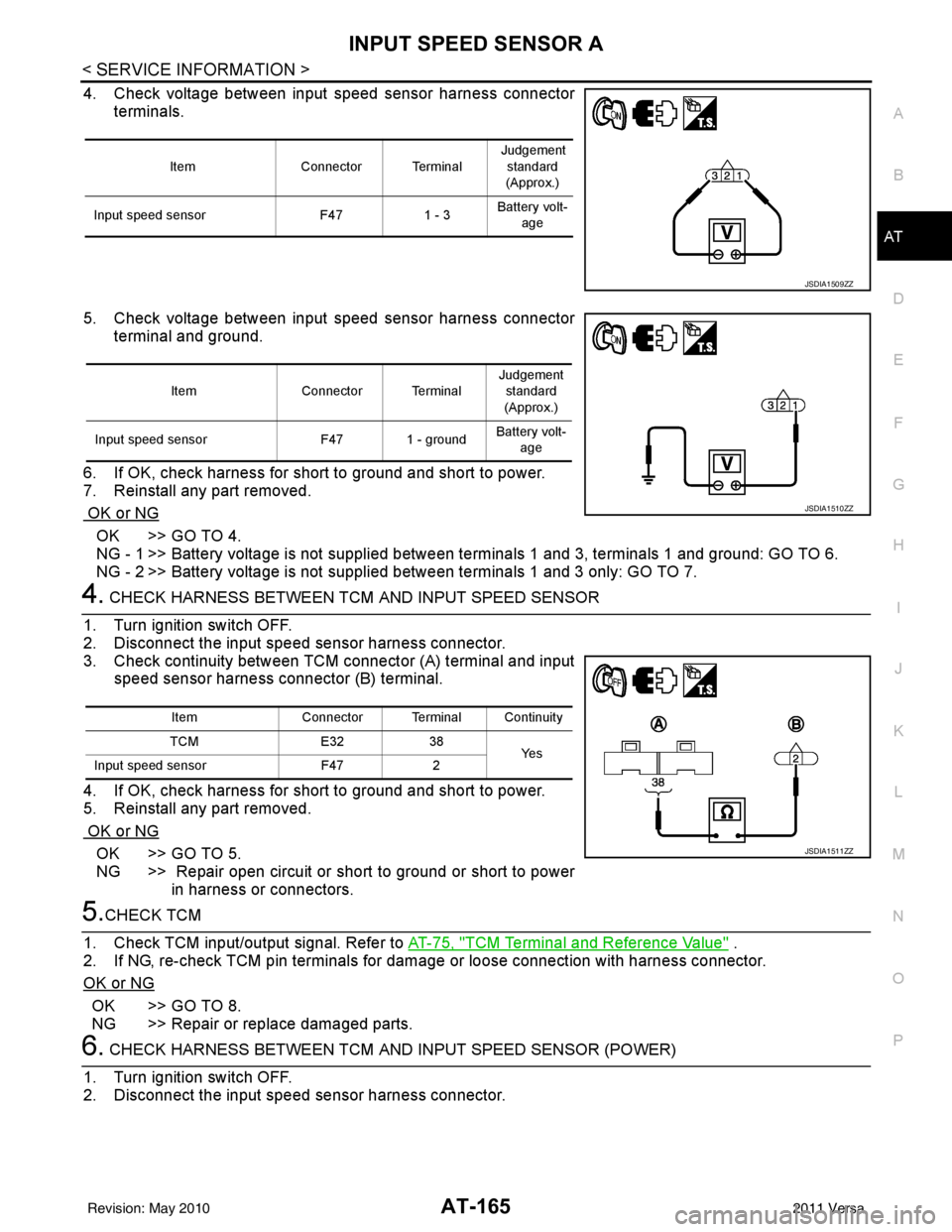
4. Check voltage between input speed sensor harness connector terminals.
5. Check voltage between input speed sensor harness connector terminal and ground.
6. If OK, check harness for short to ground and short to power.
7. Reinstall any part removed.
OK or NG
OK >> GO TO 4.
NG - 1 >> Battery voltage is not supplied between terminals 1 and 3, terminals 1 and ground: GO TO 6.
NG - 2 >> Battery voltage is not supplied between terminals 1 and 3 only: GO TO 7.
4. CHECK HARNESS BETWEEN TCM AND INPUT SPEED SENSOR
1. Turn ignition switch OFF.
2. Disconnect the input speed sensor harness connector.
3. Check continuity between TCM connector (A) terminal and input
speed sensor harness connector (B) terminal.
4. If OK, check harness for short to ground and short to power.
5. Reinstall any part removed.
OK or NG
OK >> GO TO 5.
NG >> Repair open circuit or short to ground or short to power in harness or connectors.
5.CHECK TCM
1. Check TCM input/output signal. Refer to AT-75, "
TCM Terminal and Reference Value" .
2. If NG, re-check TCM pin terminals for dam age or loose connection with harness connector.
OK or NG
OK >> GO TO 8.
NG >> Repair or replace damaged parts.
6. CHECK HARNESS BETWEEN TCM AND INPUT SPEED SENSOR (POWER)
1. Turn ignition switch OFF.
2. Disconnect the input speed sensor harness connector.
ItemConnector Terminal Judgement
standard
(Approx.)
Input speed sensor F471 - 3Battery volt-
age
JSDIA1509ZZ
Item Connector Terminal Judgement
standard
(Approx.)
Input speed sensor F47 1 - groundBattery volt-
age
JSDIA1510ZZ
Item Connector Terminal Continuity
TCM E3238
Ye s
Input speed sensor F472
JSDIA1511ZZ
Revision: May 2010 2011 Versa
Page 183 of 3787
AT-166
< SERVICE INFORMATION >
INPUT SPEED SENSOR A
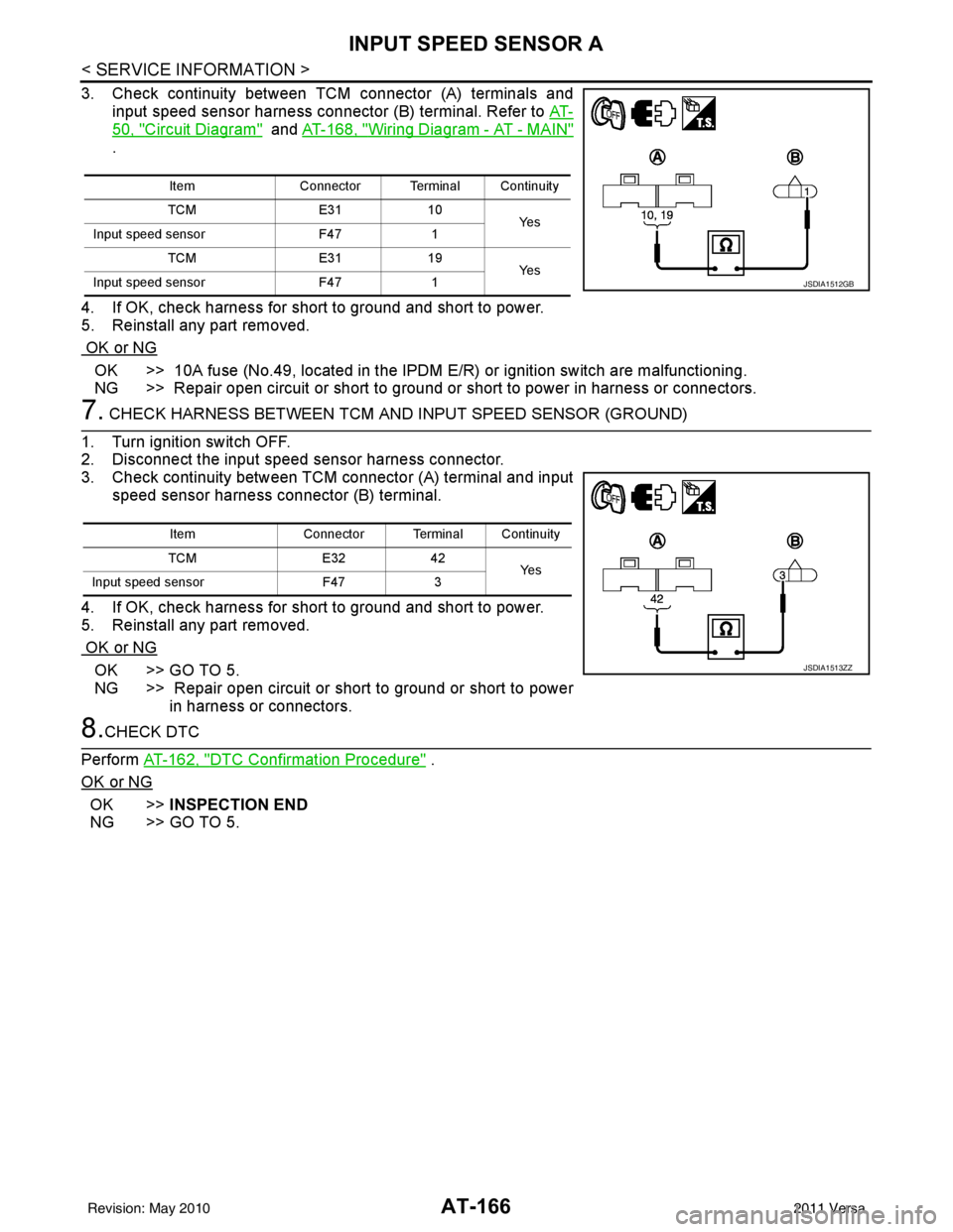
3. Check continuity between TCM connector (A) terminals and
input speed sensor harness connector (B) terminal. Refer to AT-
50, "Circuit Diagram" and AT-168, "Wiring Diagram - AT - MAIN"
.
4. If OK, check harness for short to ground and short to power.
5. Reinstall any part removed.
OK or NG
OK >> 10A fuse (No.49, located in the IPDM E/R) or ignition switch are malfunctioning.
NG >> Repair open circuit or short to ground or short to power in harness or connectors.
7. CHECK HARNESS BETWEEN TCM AND INPUT SPEED SENSOR (GROUND)
1. Turn ignition switch OFF.
2. Disconnect the input speed sensor harness connector.
3. Check continuity between TCM connector (A) terminal and input speed sensor harness connector (B) terminal.
4. If OK, check harness for short to ground and short to power.
5. Reinstall any part removed.
OK or NG
OK >> GO TO 5.
NG >> Repair open circuit or short to ground or short to power in harness or connectors.
8.CHECK DTC
Perform AT-162, "
DTC Confirmation Procedure" .
OK or NG
OK >> INSPECTION END
NG >> GO TO 5.
Item Connector Terminal Continuity
TCM E3110
Ye s
Input speed sensor F471
TCM E3119
Ye s
Input speed sensor F471
JSDIA1512GB
Item Connector Terminal Continuity
TCM E3242
Ye s
Input speed sensor F473
JSDIA1513ZZ
Revision: May 2010 2011 Versa
Page 184 of 3787
CONTROL UNIT (RAM), CONTROL UNIT (ROM)AT-167
< SERVICE INFORMATION >
DE
F
G H
I
J
K L
M A
B
AT
N
O P
CONTROL UNIT (RAM), CONTROL UNIT (ROM)
DescriptionINFOID:0000000005928232
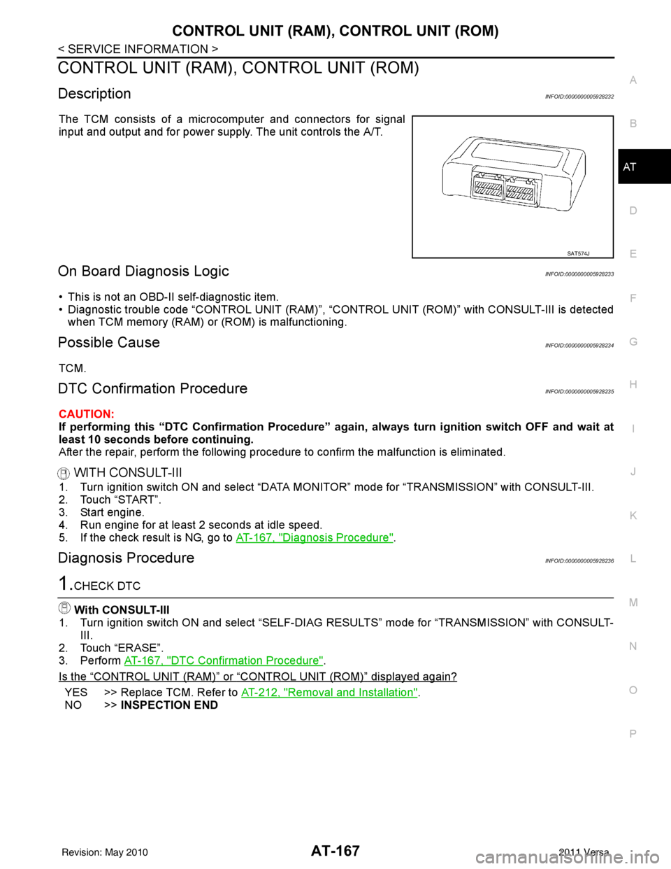
The TCM consists of a microcomputer and connectors for signal
input and output and for power supply. The unit controls the A/T.
On Board Diagnosis LogicINFOID:0000000005928233
• This is not an OBD-II self-diagnostic item.
• Diagnostic trouble code “CONTROL UNIT (RAM)”, “CONTR OL UNIT (ROM)” with CONSULT-III is detected
when TCM memory (RAM) or (ROM) is malfunctioning.
Possible CauseINFOID:0000000005928234
TCM.
DTC Confirmation ProcedureINFOID:0000000005928235
CAUTION:
If performing this “DTC Confirmati on Procedure” again, always turn ignition switch OFF and wait at
least 10 seconds before continuing.
After the repair, perform the following procedure to confirm the malfunction is eliminated.
WITH CONSULT-III
1. Turn ignition switch ON and select “DATA MO NITOR” mode for “TRANSMISSION” with CONSULT-III.
2. Touch “START”.
3. Start engine.
4. Run engine for at least 2 seconds at idle speed.
5. If the check result is NG, go to AT-167, "
Diagnosis Procedure".
Diagnosis ProcedureINFOID:0000000005928236
1.CHECK DTC
With CONSULT-III
1. Turn ignition switch ON and select “SELF-DIAG RESULTS” mode for “TRANSMISSION” with CONSULT-
III.
2. Touch “ERASE”.
3. Perform AT-167, "
DTC Confirmation Procedure".
Is the
“CONTROL UNIT (RAM)” or “CONTROL UNIT (ROM)” displayed again?
YES >> Replace TCM. Refer to AT-212, "Removal and Installation".
NO >> INSPECTION END
SAT574J
Revision: May 2010 2011 Versa
Page 186 of 3787
MAIN POWER SUPPLY AND GROUND CIRCUITAT-169
< SERVICE INFORMATION >
DE
F
G H
I
J
K L
M A
B
AT
N
O P
Diagnosis ProcedureINFOID:0000000005928238
1.CHECK TCM POWER SOURCE
1. Turn ignition switch ON. (Do not start engine.)
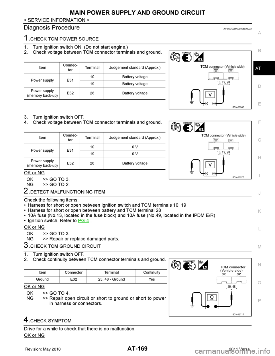
2. Check voltage between TCM connector terminals and ground.
3. Turn ignition switch OFF.
4. Check voltage between TCM connector terminals and ground.
OK or NG
OK >> GO TO 3.
NG >> GO TO 2.
2.DETECT MALFUNCTIONING ITEM
Check the following items:
• Harness for short or open between ignition switch and TCM terminals 10, 19
• Harness for short or open between battery and TCM terminal 28
• 10A fuse (No.13, located in the fuse block) and 10A fuse (No.49, located in the IPDM E/R)
• Ignition switch. Refer to PG-4
.
OK or NG
OK >> GO TO 3.
NG >> Repair or replace damaged parts.
3.CHECK TCM GROUND CIRCUIT
1. Turn ignition switch OFF.
2. Check continuity between TCM connector terminals and ground.
OK or NG
OK >> GO TO 4.
NG >> Repair open circuit or short to ground or short to power in harness or connectors.
4.CHECK SYMPTOM
Drive for a while to check that there is no malfunction.
OK or NG
Item Connec-
tor Terminal Judgement standard (Approx.)
Power supply E31 10
Battery voltage
19 Battery voltage
Power supply
(memory back-up) E32 28
Battery voltage
SCIA2656E
ItemConnec-
tor Terminal Judgement standard (Approx.)
Power supply E31 10
0 V
19 0 V
Power supply
(memory back-up) E32 28
Battery voltage
SCIA2657E
Item Connector TerminalContinuity
Ground E3225, 48 - Ground Yes
SCIA2671E
Revision: May 2010 2011 Versa
Page 189 of 3787
AT-172
< SERVICE INFORMATION >
TR SW, OD SW AND CLOSED THROTTLE, WIDE OPEN THROTTLE POSITION
SIGNAL CIRCUIT
2.CHECK TRANSMISSION RANGE SWITCH CIRCUIT
With CONSULT-III
1. Turn ignition switch ON. (Do not start engine.)
2. Select “TCM INPUT SIGNALS” in “DATA MONITOR” mode for “TRANSMISSION” with CONSULT-III.
3. Read out “P·N”, “R”, “D”, “2” and “1” position switches moving selector lever to each position.
OK or NG
OK >> GO TO 4.
NG >> Check transmission range switch circuit. Refer to AT- 9 0
.
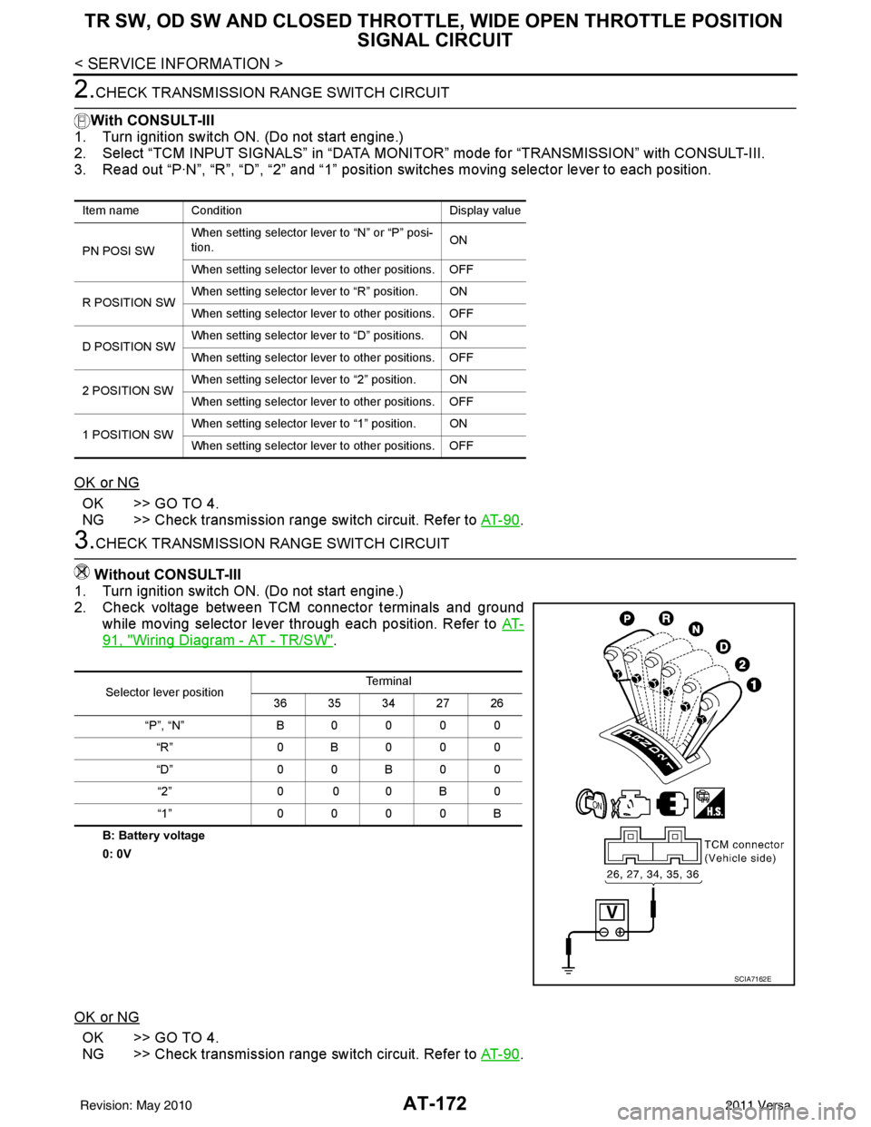
3.CHECK TRANSMISSION RANGE SWITCH CIRCUIT
Without CONSULT-III
1. Turn ignition switch ON. (Do not start engine.)
2. Check voltage between TCM connector terminals and ground while moving selector lever through each position. Refer to AT-
91, "Wiring Diagram - AT - TR/SW".
B: Battery voltage
0: 0V
OK or NG
OK >> GO TO 4.
NG >> Check transmission range switch circuit. Refer to AT- 9 0
.
Item name Condition Display value
PN POSI SW When setting selector le
ver to “N” or “P” posi-
tion. ON
When setting selector lever to other positions. OFF
R POSITION SW When setting selector lever to “R” position. ON
When setting selector lever to other positions. OFF
D POSITION SW When setting selector lever to “D” positions. ON
When setting selector lever to other positions. OFF
2 POSITION SW When setting selector lever to “2” position. ON
When setting selector lever to other positions. OFF
1 POSITION SW When setting selector lever to “1” position. ON
When setting selector lever to other positions. OFF
Selector lever position Te r m i n a l
36 35 34 27 26
“P”, “N” B0000 “R” 0B000
“D” 0 0 B 0 0
“2” 0 0 0 B 0
“1” 0000B
SCIA7162E
Revision: May 2010 2011 Versa
Page 190 of 3787
TR SW, OD SW AND CLOSED THROTTLE, WIDE OPEN THROTTLE POSITION
SIGNAL CIRCUIT
AT-173
< SERVICE INFORMATION >
DE
F
G H
I
J
K L
M A
B
AT
N
O P
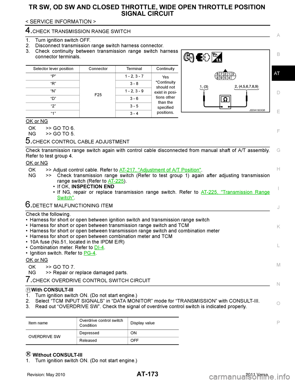
4.CHECK TRANSMISSION RANGE SWITCH
1. Turn ignition switch OFF.
2. Disconnect transmission range switch harness connector.
3. Check continuity between transmission range switch harness connector terminals.
OK or NG
OK >> GO TO 6.
NG >> GO TO 5.
5.CHECK CONTROL CABLE ADJUSTMENT
Check transmission range switch again with control cabl e disconnected from manual shaft of A/T assembly.
Refer to test group 4.
OK or NG
OK >> Adjust control cable. Refer to AT-217, "Adjustment of A/T Position".
NG >> Check transmission range switch (Refer to test group 1) again after adjusting transmission range switch (Refer to AT-225
).
• If OK, INSPECTION END
• If NG, repair or replace transmission range switch. Refer to AT-225, "
Transmission Range
Switch".
6.DETECT MALFUNCTIONING ITEM
Check the following.
• Harness for short or open between ignition switch and transmission range switch
• Harness for short or open between transmission range switch and TCM
• Harness for short or open between transmission range switch and combination meter
• Harness for short or open between combination meter and TCM
• 10A fuse (No.51, located in the IPDM E/R)
• Combination meter. Refer to DI-4
.
• Ignition switch. Refer to PG-4
.
OK or NG
OK >> GO TO 7.
NG >> Repair or replace damaged parts.
7.CHECK OVERDRIVE CO NTROL SWITCH CIRCUIT
With CONSULT-III
1. Turn ignition switch ON. (Do not start engine.)
2. Select “TCM INPUT SIGNALS” in “DATA MONI TOR” mode for “TRANSMISSION” with CONSULT-III.
3. Read out “OVERDRIVE SW”. Check the signal of ov erdrive control switch is indicated properly.
Without CONSULT-III
1. Turn ignition switch ON. (Do not start engine.)
Selector lever position Connector Terminal Continuity
“P”
F251 - 2, 3 - 7
Ye s
*Continuity should not
exist in posi-
tions other than the
specified
positions.
“R”
3 - 8
“N” 1 - 2, 3 - 9
“D” 3 - 6
“2” 3 - 5
“1” 3 - 4
JSDIA1503GB
Item nameOverdrive control switch
ConditionDisplay value
OVERDRIVE SW Depressed
ON
Released OFF
Revision: May 2010 2011 Versa
Page 191 of 3787
AT-174
< SERVICE INFORMATION >
TR SW, OD SW AND CLOSED THROTTLE, WIDE OPEN THROTTLE POSITION
SIGNAL CIRCUIT
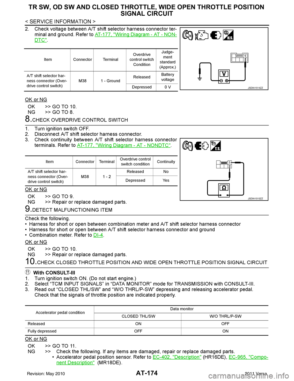
2. Check voltage between A/T shift selector harness connector ter-
minal and ground. Refer to AT-177, "
Wiring Diagram - AT - NON-
DTC".
OK or NG
OK >> GO TO 10.
NG >> GO TO 8.
8.CHECK OVERDRIVE CONTROL SWITCH
1. Turn ignition switch OFF.
2. Disconnect A/T shift selector harness connector.
3. Check continuity between A/T shift selector harness connector terminals. Refer to AT-177, "
Wiring Diagram - AT - NONDTC".
OK or NG
OK >> GO TO 9.
NG >> Repair or replace damaged parts.
9.DETECT MALFUNCTIONING ITEM
Check the following.
• Harness for short or open between combination meter and A/T shift selector harness connector
• Harness for short or open between A/T shift selector harness connector and ground
• Combination meter. Refer to DI-4
.
OK or NG
OK >> GO TO 10.
NG >> Repair or replace damaged parts.
10.CHECK CLOSED THROTTLE POSI TION AND WIDE OPEN THROTTLE POSITION SIGNAL CIRCUIT
With CONSULT-III
1. Turn ignition switch ON. (Do not start engine.)
2. Select “TCM INPUT SIGNALS” in “DATA MONITOR” mode for TRANSMISSION with CONSULT-III.
3. Read out “CLOSED THL/SW” and “W/O THRL/P-S W” depressing and releasing accelerator pedal.
Check that the signals of throttle position are indicated properly.
OK or NG
OK >> GO TO 11.
NG >> Check the following. If any items are damaged, repair or replace damaged parts. • Accelerator pedal position sensor. Refer to EC-402, "
Description" (HR16DE), EC-965, "Compo-
nent Description" (MR18DE).
Item Connector Terminal Overdrive
control switch
Condition Judge-
ment
standard
(Approx.)
A/T shift selector har-
ness connector (Over-
drive control switch) M38 1 - Ground
Released
Battery
voltage
Depressed 0 V
JSDIA1514ZZ
Item Connector Terminal Overdrive control
switch condition Continuity
A/T shift selector har-
ness connector (Over-
drive control switch) M38 1 - 2
Released No
Depressed Yes
JSDIA1515ZZ
Accelerator pedal condition Data monitor
CLOSED THL/SW W/O THRL/P-SW
Released ONOFF
Fully depressed OFFON
Revision: May 2010 2011 Versa
Page 198 of 3787
TROUBLE DIAGNOSIS FOR SYMPTOMSAT-181
< SERVICE INFORMATION >
DE
F
G H
I
J
K L
M A
B
AT
N
O P
OD OFF indicator lamp does not come on for abou t 2 seconds when turning ignition switch to ON.
DIAGNOSTIC PROCEDURE
1.CHECK CAN COMMUNICATION LINE
Perform self-diagnosis. Refer to AT-77, "
CONSULT-III Function (TRANSMISSION)" .
Is a malfunction in CAN communication indicated in the results?
YES >> Check CAN communication line. Refer to AT- 8 7 .
NO >> GO TO 2.
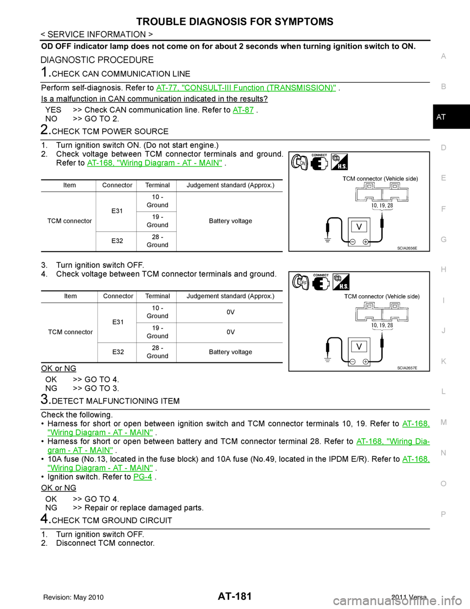
2.CHECK TCM POWER SOURCE
1. Turn ignition switch ON. (Do not start engine.)
2. Check voltage between TCM connector terminals and ground. Refer to AT-168, "
Wiring Diagram - AT - MAIN" .
3. Turn ignition switch OFF.
4. Check voltage between TCM connector terminals and ground.
OK or NG
OK >> GO TO 4.
NG >> GO TO 3.
3.DETECT MALFUNCTIONING ITEM
Check the following.
• Harness for short or open between ignition switch and TCM connector terminals 10, 19. Refer to AT-168,
"Wiring Diagram - AT - MAIN" .
• Harness for short or open between battery and TCM connector terminal 28. Refer to AT-168, "
Wiring Dia-
gram - AT - MAIN" .
• 10A fuse (No.13, located in the fuse block) and 10A fuse (No.49, located in the IPDM E/R). Refer to AT-168,
"Wiring Diagram - AT - MAIN" .
• Ignition switch. Refer to PG-4
.
OK or NG
OK >> GO TO 4.
NG >> Repair or replace damaged parts.
4.CHECK TCM GROUND CIRCUIT
1. Turn ignition switch OFF.
2. Disconnect TCM connector.
Item Connector Terminal Judgement standard (Approx.)
TCM connector E3110 -
Ground
Battery voltage
19 -
Ground
E32 28 -
Ground
SCIA2656E
Item Connector Terminal Judgement standard (Approx.)
TCM connector E3110 -
Ground 0V
19 -
Ground 0V
E32 28 -
Ground Battery voltage
SCIA2657E
Revision: May 2010
2011 Versa