2011 NISSAN LATIO lock
[x] Cancel search: lockPage 3349 of 3787
TROUBLE DIAGNOSISMTC-33
< SERVICE INFORMATION >
C
DE
F
G H
I
K L
M A
B
MTC
N
O P
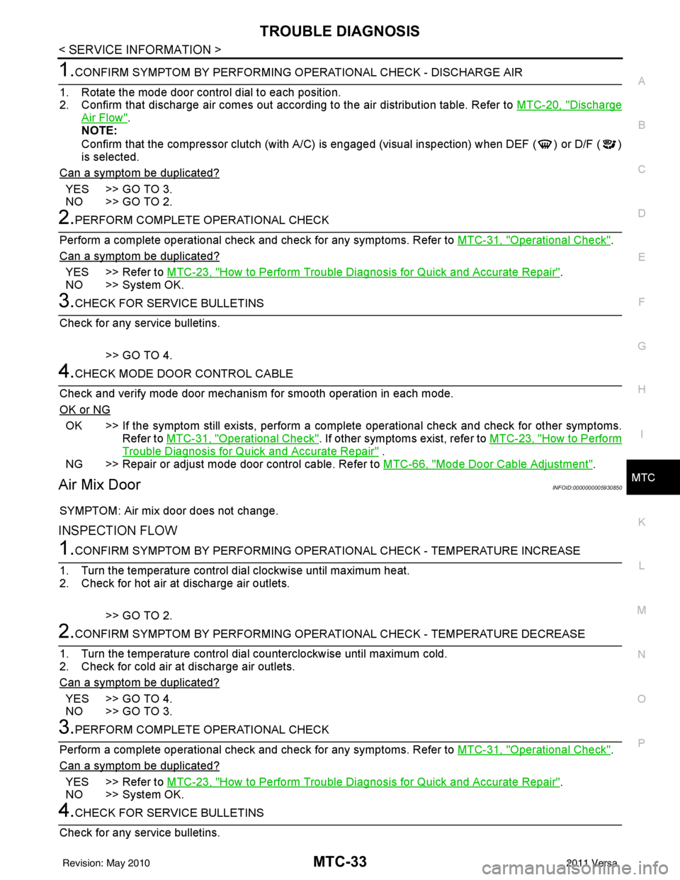
1.CONFIRM SYMPTOM BY PERFORMING O PERATIONAL CHECK - DISCHARGE AIR
1. Rotate the mode door control dial to each position.
2. Confirm that discharge air comes out accord ing to the air distribution table. Refer to MTC-20, "
Discharge
Air Flow".
NOTE:
Confirm that the compressor clutch (with A/C) is engaged (visual inspection) when DEF ( ) or D/F ( )
is selected.
Can a symptom be duplicated?
YES >> GO TO 3.
NO >> GO TO 2.
2.PERFORM COMPLETE OPERATIONAL CHECK
Perform a complete operational check and check for any symptoms. Refer to MTC-31, "
Operational Check".
Can a symptom be duplicated?
YES >> Refer to MTC-23, "How to Perform Trouble Diagnosis for Quick and Accurate Repair".
NO >> System OK.
3.CHECK FOR SERVICE BULLETINS
Check for any service bulletins.
>> GO TO 4.
4.CHECK MODE DOOR CONTROL CABLE
Check and verify mode door mechanism for smooth operation in each mode.
OK or NG
OK >> If the symptom still exists, perform a comple te operational check and check for other symptoms.
Refer to MTC-31, "
Operational Check". If other symptoms exist, refer to MTC-23, "How to Perform
Trouble Diagnosis for Quick and Accurate Repair" .
NG >> Repair or adjust mode door control cable. Refer to MTC-66, "
Mode Door Cable Adjustment".
Air Mix DoorINFOID:0000000005930850
SYMPTOM: Air mix door does not change.
INSPECTION FLOW
1.CONFIRM SYMPTOM BY PERFORMING OPERATIONAL CHECK - TEMPERATURE INCREASE
1. Turn the temperature control dial clockwise until maximum heat.
2. Check for hot air at discharge air outlets.
>> GO TO 2.
2.CONFIRM SYMPTOM BY PERFORMING OPERAT IONAL CHECK - TEMPERATURE DECREASE
1. Turn the temperature control dial counterclockwise until maximum cold.
2. Check for cold air at discharge air outlets.
Can a symptom be duplicated?
YES >> GO TO 4.
NO >> GO TO 3.
3.PERFORM COMPLETE OPERATIONAL CHECK
Perform a complete operational check and check for any symptoms. Refer to MTC-31, "
Operational Check".
Can a symptom be duplicated?
YES >> Refer to MTC-23, "How to Perform Trouble Diagnosis for Quick and Accurate Repair".
NO >> System OK.
4.CHECK FOR SERVICE BULLETINS
Check for any service bulletins.
Revision: May 2010 2011 Versa
Page 3352 of 3787
![NISSAN LATIO 2011 Service Repair Manual MTC-36
< SERVICE INFORMATION >
TROUBLE DIAGNOSIS
NG >> Check power supply circuit and 15A fuses [Nos. 15 and 17, located in the fuse block (J/B)].Refer to PG-4, "
Schematic".
• If fuses are OK, rein NISSAN LATIO 2011 Service Repair Manual MTC-36
< SERVICE INFORMATION >
TROUBLE DIAGNOSIS
NG >> Check power supply circuit and 15A fuses [Nos. 15 and 17, located in the fuse block (J/B)].Refer to PG-4, "
Schematic".
• If fuses are OK, rein](/manual-img/5/57357/w960_57357-3351.png)
MTC-36
< SERVICE INFORMATION >
TROUBLE DIAGNOSIS
NG >> Check power supply circuit and 15A fuses [Nos. 15 and 17, located in the fuse block (J/B)].Refer to PG-4, "
Schematic".
• If fuses are OK, reinstall fuses and GO TO 3.
• If fuses are NG, replace fuse and check harness for short circuit. Repair or replace if necessary.
3.CHECK BLOWER MOTOR RELAY POWER SUPPLY CIRCUITS
1. Turn ignition switch OFF.
2. Disconnect blower motor relay connector.
3. Turn ignition switch ON.
4. Check voltage between blower motor relay harness connector J- 1 terminal 1, 5 and ground.
OK or NG
OK >> GO TO 4.
NG >> Repair harness or connector.
4.CHECK BLOWER MOTOR RELAY (S WITCH SIDE) CIRCUIT FOR OPEN
1. Turn ignition switch OFF.
2. Check continuity between blower motor relay harness connector J-1 (A) terminal 3 and front blower motor harness connector
M62 (B) terminal 1.
OK or NG
OK >> GO TO 5.
NG >> Repair harness or connector.
5.CHECK BLOWER MOTOR RELAY GROUND CIRCUIT
Check continuity between blower motor relay harness connector J-1
terminal 2 and ground.
OK or NG
OK >> Replace blower motor relay.
NG >> Repair harness or connector.
6.CHECK FRONT BLOWER MOTOR
Check continuity between front blower motor terminals 1 and 2.
NOTE:
Ensure that there are no foreign particles inside the A/C unit assem-
bly for a smooth rotation of the front blower motor.
OK or NG
OK >> GO TO 7.
NG >> Replace front blower motor. Refer to MTC-63, "
Removal
and Installation".
7.CHECK CIRCUIT CONTINUITY BETWEEN FRONT BLOWER MOTOR AND FRONT AIR CONTROL
1 - Ground Battery voltage should exist.
5 - Ground Battery voltage should exist.
WJIA1783E
Continuity should exist.
WJIA2263E
Continuity should exist.
WJIA2264E
1 - 2
: Continuity should exist.
WJIA2230E
Revision: May 2010 2011 Versa
Page 3358 of 3787
MTC-42
< SERVICE INFORMATION >
TROUBLE DIAGNOSIS
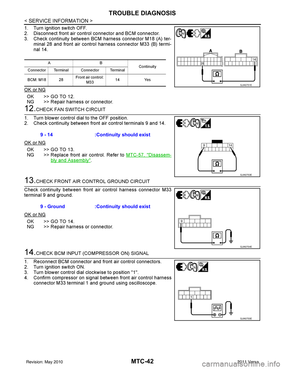
1. Turn ignition switch OFF.
2. Disconnect front air control connector and BCM connector.
3. Check continuity between BCM harness connector M18 (A) ter-minal 28 and front air control harness connector M33 (B) termi-
nal 14.
OK or NG
OK >> GO TO 12.
NG >> Repair harness or connector.
12.CHECK FAN SWITCH CIRCUIT
1. Turn blower control dial to the OFF position.
2. Check continuity between front air control terminals 9 and 14.
OK or NG
OK >> GO TO 13.
NG >> Replace front air control. Refer to MTC-57, "
Disassem-
bly and Assembly".
13.CHECK FRONT AIR CONTROL GROUND CIRCUIT
Check continuity between front air control harness connector M33
terminal 9 and ground.
OK or NG
OK >> GO TO 14.
NG >> Repair harness or connector.
14.CHECK BCM INPUT (COMPRESSOR ON) SIGNAL
1. Reconnect BCM connector and front air control connectors.
2. Turn ignition switch ON.
3. Turn blower control dial clockwise to position "1".
4. Confirm compressor on signal between front air control harness connector M33 terminal 1 and ground using oscilloscope.
AB Continuity
Connector Terminal Connector Terminal
BCM: M18 28 Front air control:
M33 14
Yes
SJIA0751E
9 - 14 :Continuity should exist
SJIA0753E
9 - Ground :Continuity should exist
SJIA0754E
SJIA0755E
Revision: May 2010 2011 Versa
Page 3360 of 3787
MTC-44
< SERVICE INFORMATION >
TROUBLE DIAGNOSIS
OK or NG
OK >> • GO TO 18 (with CVT).• GO TO 19 (without CVT).
NG >> GO TO 21.
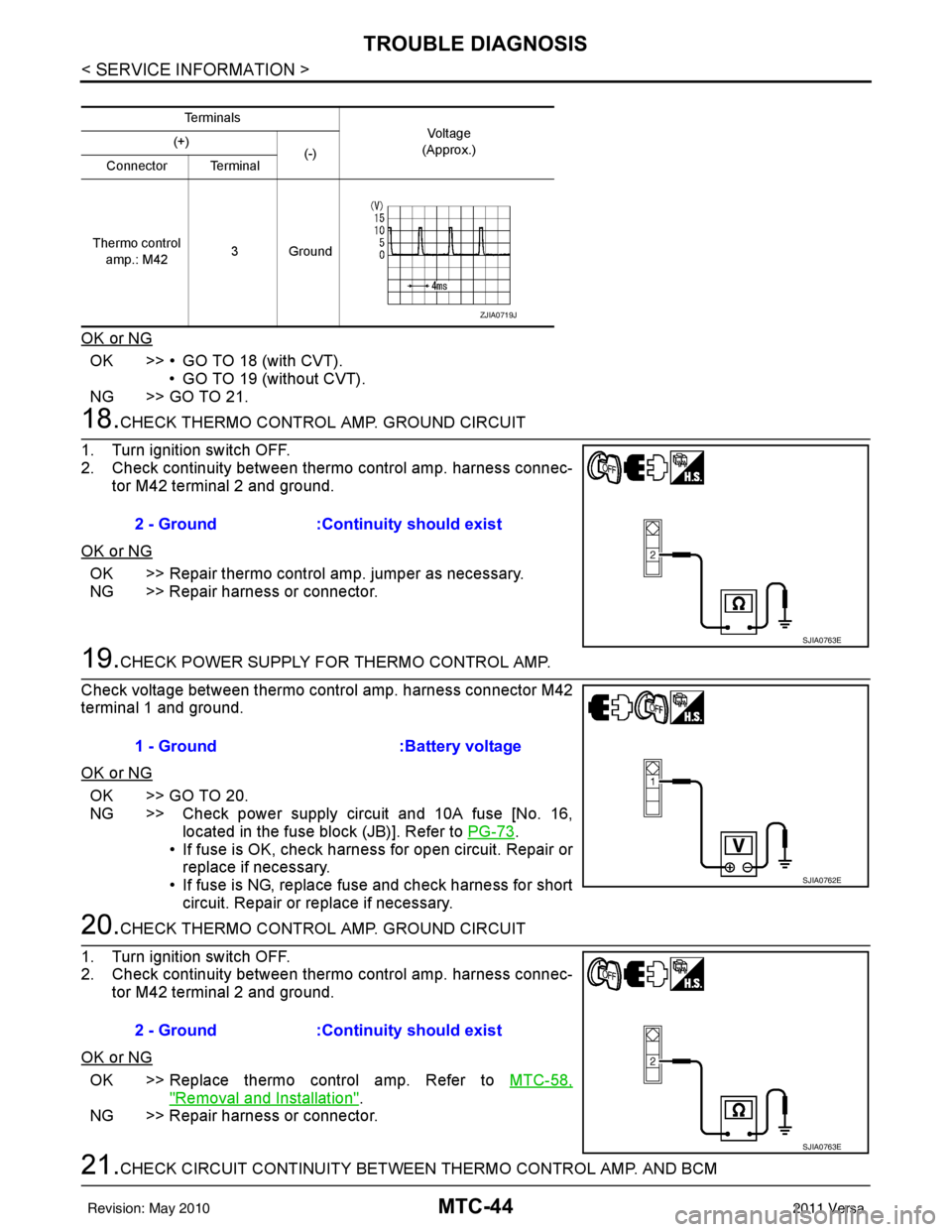
18.CHECK THERMO CONTROL AMP. GROUND CIRCUIT
1. Turn ignition switch OFF.
2. Check continuity between thermo control amp. harness connec- tor M42 terminal 2 and ground.
OK or NG
OK >> Repair thermo control amp. jumper as necessary.
NG >> Repair harness or connector.
19.CHECK POWER SUPPLY FOR THERMO CONTROL AMP.
Check voltage between thermo control amp. harness connector M42
terminal 1 and ground.
OK or NG
OK >> GO TO 20.
NG >> Check power supply circuit and 10A fuse [No. 16, located in the fuse block (JB)]. Refer to PG-73
.
• If fuse is OK, check harness for open circuit. Repair or
replace if necessary.
• If fuse is NG, replace fuse and check harness for short circuit. Repair or replace if necessary.
20.CHECK THERMO CONTROL AMP. GROUND CIRCUIT
1. Turn ignition switch OFF.
2. Check continuity between thermo control amp. harness connec- tor M42 terminal 2 and ground.
OK or NG
OK >> Replace thermo control amp. Refer to MTC-58,
"Removal and Installation".
NG >> Repair harness or connector.
21.CHECK CIRCUIT CONTINUITY BETWEEN THERMO CONTROL AMP. AND BCM
Te r m i n a l s
Vo l ta g e
(Approx.)
(+)
(-)
Connector Terminal
Thermo control amp.: M42 3Ground
ZJIA0719J
2 - Ground
:Continuity should exist
SJIA0763E
1 - Ground :Battery voltage
SJIA0762E
2 - Ground:Continuity should exist
SJIA0763E
Revision: May 2010 2011 Versa
Page 3362 of 3787
MTC-46
< SERVICE INFORMATION >
TROUBLE DIAGNOSIS
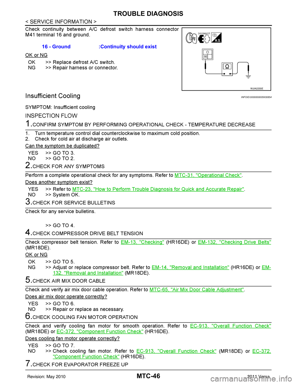
Check continuity between A/C defrost switch harness connector
M41 terminal 16 and ground.
OK or NG
OK >> Replace defrost A/C switch.
NG >> Repair harness or connector.
Insufficient CoolingINFOID:0000000005930854
SYMPTOM: Insufficient cooling
INSPECTION FLOW
1.CONFIRM SYMPTOM BY PERFORMING OPERATIONAL CHECK - TEMPERATURE DECREASE
1. Turn temperature control dial counterclockwise to maximum cold position.
2. Check for cold air at discharge air outlets.
Can the symptom be duplicated?
YES >> GO TO 3.
NO >> GO TO 2.
2.CHECK FOR ANY SYMPTOMS
Perform a complete operational check for any symptoms. Refer to MTC-31, "
Operational Check".
Does another symptom exist?
YES >> Refer to MTC-23, "How to Perform Trouble Diagnosis for Quick and Accurate Repair".
NO >> System OK.
3.CHECK FOR SERVICE BULLETINS
Check for any service bulletins.
>> GO TO 4.
4.CHECK COMPRESSOR DRIVE BELT TENSION
Check compressor belt tension. Refer to EM-13, "
Checking" (HR16DE) or EM-132, "Checking Drive Belts"
(MR18DE).
OK or NG
OK >> GO TO 5.
NG >> Adjust or replace compressor belt. Refer to EM-14, "
Removal and Installation" (HR16DE) or EM-
132, "Removal and Installation" (MR18DE).
5.CHECK AIR MIX DOOR CABLE
Check and verify air mix door cable operation. Refer to MTC-65, "
Air Mix Door Cable Adjustment".
Does air mix door operate correctly?
YES >> GO TO 6.
NO >> Repair or replace as necessary.
6.CHECK COOLING FAN MOTOR OPERATION
Check and verify cooling fan motor for smooth operation. Refer to EC-913, "
Overall Function Check"
(MR18DE) or EC-372, "Component Function Check" (HR16DE).
Does cooling fan motor operate correctly?
YES >> GO TO 7.
NO >> Check cooling fan motor. Refer to EC-913, "
Overall Function Check" (MR18DE) or EC-372,
"Component Function Check" (HR16DE).
7.CHECK FOR EVAPORATOR FREEZE UP16 - Ground :Continuity should exist
WJIA2255E
Revision: May 2010
2011 Versa
Page 3369 of 3787
TROUBLE DIAGNOSISMTC-53
< SERVICE INFORMATION >
C
DE
F
G H
I
K L
M A
B
MTC
N
O P
Insufficient HeatingINFOID:0000000005930855
SYMPTOM: Insufficient heating
INSPECTION FLOW
1.CONFIRM SYMPTOM BY PERFORMING OPERAT IONAL CHECK - TEMPERATURE INCREASE
1. Turn temperature control dial clockwise to maximum heat position.
2. Check for hot air at discharge air outlets.
Can the symptom be duplicated?
YES >> GO TO 3.
NO >> GO TO 2.
2.CHECK FOR ANY SYMPTOMS
Perform a complete operational check for any symptoms. Refer to MTC-31, "
Operational Check" .
Does another symptom exist?
YES >> Refer to MTC-23, "How to Perform Trouble Diagnosis for Quick and Accurate Repair" .
NO >> System OK.
3.CHECK FOR SERVICE BULLETINS
Check for any service bulletins.
>> GO TO 4.
4.CHECK COOLANT SYSTEM
1. Check engine coolant level. Refer to CO-11, "
Inspection" (HR16DE) or CO-36, "Inspection" (MR18DE).
2. Check hoses for leaks or kinks.
3. Check Radiator cap. Refer to CO-14, "
Checking Radiator Cap" HR16DE or CO-39, "Checking Radiator
Cap" (MR18DE).
OK or NG
OK >> GO TO 5.
NG >> Repair/replace as necessary.
5.CHECK AIR MIX DOOR CABLE
Check air mix door cable operation. Refer to MTC-65, "
Air Mix Door Cable Adjustment" .
OK or NG
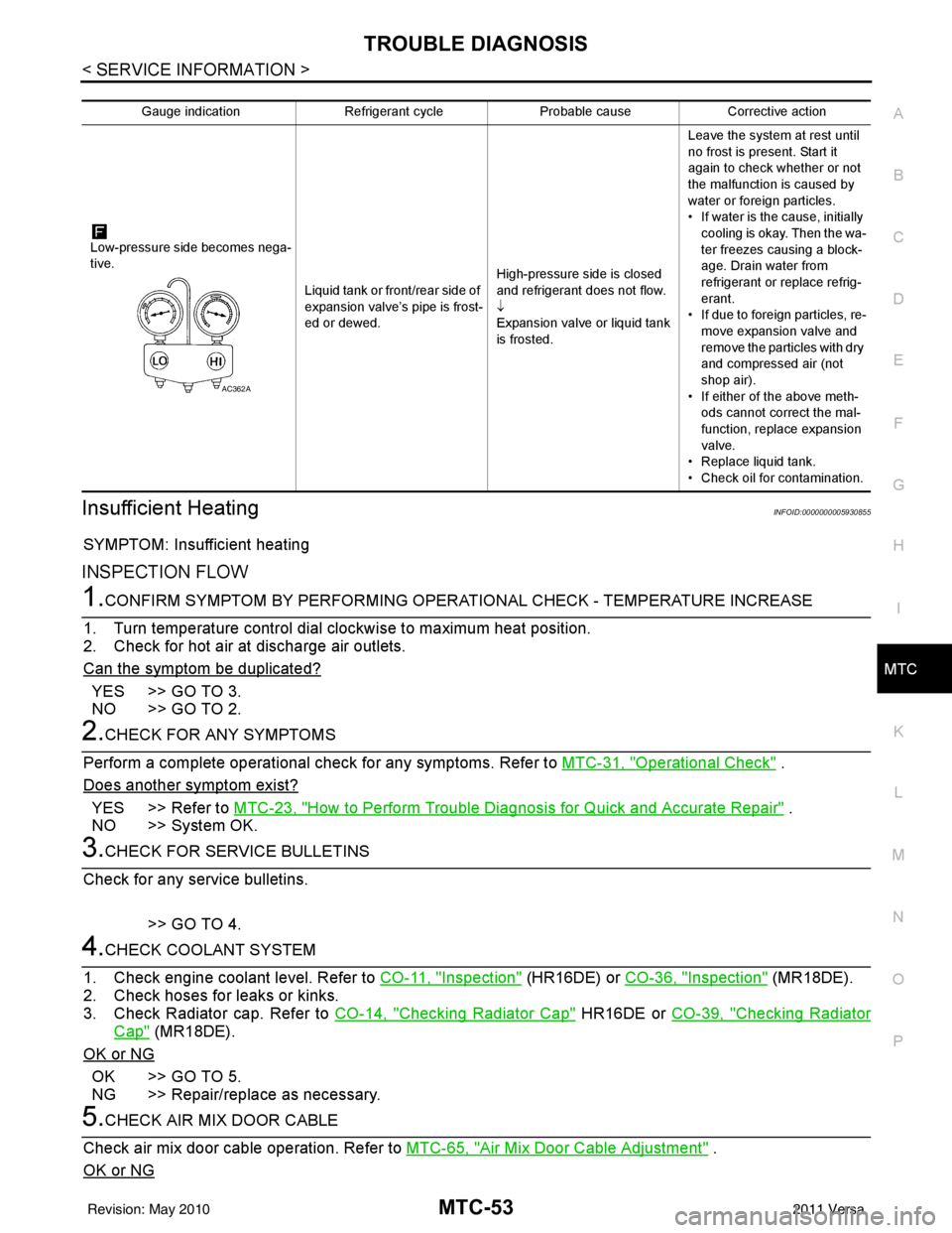
Gauge indication Refrigerant cycleProbable causeCorrective action
Low-pressure side becomes nega-
tive. Liquid tank or front/rear side of
expansion valve’s pipe is frost-
ed or dewed.High-pressure side is closed
and refrigerant does not flow.
↓
Expansion valve or liquid tank
is frosted.Leave the system at rest until
no frost is present. Start it
again to check whether or not
the malfunction is caused by
water or foreign particles.
• If water is the cause, initially
cooling is okay. Then the wa-
ter freezes causing a block-
age. Drain water from
refrigerant or replace refrig-
erant.
• If due to foreign particles, re-
move expansion valve and
remove the particles with dry
and compressed air (not
shop air).
• If either of the above meth- ods cannot correct the mal-
function, replace expansion
valve.
• Replace liquid tank.
• Check oil for contamination.
AC362A
Revision: May 2010 2011 Versa
Page 3379 of 3787
BLOWER MOTORMTC-63
< SERVICE INFORMATION >
C
DE
F
G H
I
K L
M A
B
MTC
N
O P
BLOWER MOTOR
Removal and InstallationINFOID:0000000005930862
REMOVAL
1. Remove instrument panel and pad. Refer to IP-11, "Component Parts".
2. Remove side ventilator duct (right). Refer to MTC-69, "
Removal and Installation".
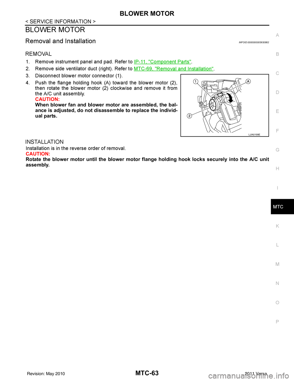
3. Disconnect blower motor connector (1).
4. Push the flange holding hook (A) toward the blower motor (2), then rotate the blower motor (2) clockwise and remove it from
the A/C unit assembly.
CAUTION:
When blower fan and blower motor are assembled, the bal-
ance is adjusted, do not di sassemble to replace the individ-
ual parts.
INSTALLATION
Installation is in the reverse order of removal.
CAUTION:
Rotate the blower motor until th e blower motor flange holding ho ok locks securely into the A/C unit
assembly.
LJIA0199E
Revision: May 2010 2011 Versa
Page 3412 of 3787
MTC-96
< SERVICE INFORMATION >
SERVICE DATA AND SPECIFICATIONS (SDS)
SERVICE DATA AND SPECIFICATIONS (SDS)
CompressorINFOID:0000000005930888
OilINFOID:0000000005930889
RefrigerantINFOID:0000000005930890
ApplicationMR18DE - TYPE 1 and HR16DE MR18DE - TYPE 2
Compressor model Calsonic Kansei make CR-10Calsonic Kansei make CSV511
Type Vane rotaryVariable displacement swash plate
Displacement
cm
3 (in3) / revolution maximum
96 (5.86) 105 (6.41)
Cylinder bore × stroke
mm (in) maximum
— 34.8 (1.37) × 22.1 (0.87)
Direction of rotation Clockwise (viewed from drive end)
Drive belt Poly-V Ribbed 6-Groove
ApplicationMR18DE - TYPE 1 and HR16DE MR18DE - TYPE 2
Compressor model Calsonic Kansei make CR-10Calsonic Kansei make CSV511
Type NISSAN A/C System Oil Type RNISSAN A/C System Oil Type S
Capacity
m (US fl oz,
lmp fl oz) Total in system
120 (4.1, 4.2) 100 (3.4, 3.5)
Compressor (service
part) charging
amount Refer to
MTC-17, "
Maintenance of Oil Quanti-
ty in Compressor" . Refer to MTC-17, "
Maintenance of Oil
Quantity in Compressor" .
Ty p e
HFC-134a (R-134a)
Capacity
kg (lb) 0.45
± 0.05 (0.99 ± 0.11)
Revision: May 2010 2011 Versa