2011 NISSAN LATIO belt
[x] Cancel search: beltPage 1923 of 3787
![NISSAN LATIO 2011 Service Repair Manual TROUBLE DIAGNOSIS - SPECIFICATION VALUEEC-629
< SERVICE INFORMATION > [MR18DE]
C
D
E
F
G H
I
J
K L
M A
EC
NP
O
OK >>
INSPECTION END
NG >> GO TO 15.
15.DISCONNECT AND RECONNECT ECM HARNESS CONNECTOR
1. NISSAN LATIO 2011 Service Repair Manual TROUBLE DIAGNOSIS - SPECIFICATION VALUEEC-629
< SERVICE INFORMATION > [MR18DE]
C
D
E
F
G H
I
J
K L
M A
EC
NP
O
OK >>
INSPECTION END
NG >> GO TO 15.
15.DISCONNECT AND RECONNECT ECM HARNESS CONNECTOR
1.](/manual-img/5/57357/w960_57357-1922.png)
TROUBLE DIAGNOSIS - SPECIFICATION VALUEEC-629
< SERVICE INFORMATION > [MR18DE]
C
D
E
F
G H
I
J
K L
M A
EC
NP
O
OK >>
INSPECTION END
NG >> GO TO 15.
15.DISCONNECT AND RECONNECT ECM HARNESS CONNECTOR
1. Stop the engine.
2. Disconnect ECM harness connector. Check pin term inal and connector for damage, and then reconnect it.
>> GO TO 16.
16.CHECK “A/F ALPHA-B1”
1. Start engine.
2. Select “A/F ALPHA-B1” in “SPEC” of “DATA MONITOR” mode, and make sure that the indication is within
the SP value.
OK or NG
OK >> INSPECTION END
NG >> Detect malfunctioning part according to EC-592, "
Symptom Matrix Chart".
17.CHECK “B/FUEL SCHDL”
Select “B/FUEL SCHDL” in “SPEC” of “DATA MONITOR” m ode, and make sure that the indication is within the
SP value.
OK or NG
OK >> INSPECTION END
NG (More than the SP value)>>GO TO 18.
NG (Less than the SP value)>>GO TO 25.
18.DETECT MALFUNCTIONING PART
1. Check for the cause of large engine friction. Refer to the following.
- Engine oil level is too high
- Engine oil viscosity
- Belt tension of alternator, A/C compressor, etc. is excessive
- Noise from engine
- Noise from transmission, etc.
2. Check for the cause of insufficient combustion. Refer to the following.
- Valve clearance malfunction
- Intake valve timing control function malfunction
- Camshaft sprocket installation malfunction, etc.
>> Repair or replace malfunctioning part, and then GO TO 30.
19.CHECK INTAKE SYSTEM
Check for the cause of uneven air flow through mass air flow sensor. Refer to the following.
• Crushed air ducts
• Malfunctioning seal of air cleaner element
• Uneven dirt of air cleaner element
• Improper specification of intake air system
OK or NG
OK >> GO TO 21.
NG >> Repair or replace malfunctioning part, and then GO TO 20.
20.CHECK “A/F ALPHA-B1” AND “B/FUEL SCHDL”
Select “A/F ALPHA-B1” and “B/FUEL SCHDL” in “SPEC” of “DATA MONITOR” mode, and make sure that the
each indication is within the SP value.
OK or NG
OK >> INSPECTION END
NG (“B/FUEL SCHDL” is more, “A/F ALPHA- B1” is less than the SP value)>>GO TO 21.
21.DISCONNECT AND RECONNECT MASS AI R FLOW SENSOR HARNESS CONNECTOR
1. Stop the engine.
Revision: May 2010 2011 Versa
Page 2331 of 3787
EI-1
BODY
C
DE
F
G H
J
K L
M
SECTION EI
A
B
EI
N
O P
CONTENTS
EXTERIOR & INTERIOR
PRECAUTION ....... ........................................3
PRECAUTIONS .............................................. .....3
Precaution for Supplemental Restraint System
(SRS) "AIR BAG" and "SEAT BELT PRE-TEN-
SIONER" ............................................................. ......
3
Precaution Necessary for Steering Wheel Rota-
tion After Battery Disconnect ............................... ......
3
Precaution .................................................................4
PREPARATION ............................................5
PREPARATION .............................................. .....5
Special Service Tool ........................................... ......5
Commercial Service Tool ..........................................5
SYMPTOM DIAGNOSIS ...............................6
SQUEAK AND RATTLE TROUBLE DIAGNO-
SIS .................................................................. .....
6
Work Flow ........................................................... ......6
Generic Squeak and Rattle Troubleshooting ............8
Diagnostic Worksheet .............................................10
CLIP AND FASTENER .......................................12
Description .......................................................... ....12
ON-VEHICLE REPAIR .................................15
FRONT BUMPER ........................................... ....15
Removal and Installation .........................................15
REAR BUMPER ............................................. ....18
Component .......................................................... ....18
Removal and Installation - Hatchback .....................19
Removal and Installation - Sedan ....................... ....21
FRONT GRILLE .................................................23
Removal and Installation .........................................23
COWL TOP .........................................................24
Removal and Installation .........................................24
FENDER PROTECTOR ....................................26
Component .......................................................... ....26
Removal and Installation .........................................26
ROOF SIDE MOLDING .....................................27
Component ..............................................................27
Removal and Installation .........................................27
DOOR OUTSIDE MOLDING .............................29
Component ..............................................................29
Removal and Installation .........................................30
CENTER MUD GUARD .....................................32
Removal and Installation .........................................32
TRUNK LID FINISHER ......................................33
Removal and Installation .........................................33
REAR AIR SPOILER .........................................34
Removal and Installation .........................................34
DOOR FINISHER ..............................................36
Removal and Installation .........................................36
BACK DOOR TRIM ...........................................40
Removal and Installation ..................................... ....40
BODY SIDE TRIM .............................................41
Component ..............................................................41
Removal and Installation .........................................42
REAR PARCEL SHELF FINISHER ..................47
Removal and Installation .........................................47
FLOOR TRIM ....................................................48
Removal and Installation .........................................48
HEADLINING ....................................................50
Component ..............................................................50
Removal and Installation - Hatchback .....................52
Removal and Installation - Sedan ............................54
LUGGAGE FLOOR TRIM .................................56
Revision: May 2010 2011 Versa
Page 2333 of 3787
PRECAUTIONSEI-3
< PRECAUTION >
C
DE
F
G H
J
K L
M A
B
EI
N
O P
PRECAUTION
PRECAUTIONS
Precaution for Supplemental Restraint System (SRS) "AIR BAG" and "SEAT BELT
PRE-TENSIONER"
INFOID:0000000005929545
The Supplemental Restraint System such as “AIR BAG” and “SEAT BELT PRE-TENSIONER”, used along
with a front seat belt, helps to reduce the risk or severi ty of injury to the driver and front passenger for certain
types of collision. This system includes seat belt switch inputs and dual stage front air bag modules. The SRS
system uses the seat belt switches to determine the front air bag deployment, and may only deploy one front
air bag, depending on the severity of a collision and w hether the front occupants are belted or unbelted.
Information necessary to service the system safely is included in the SRS and SB section of this Service Man-
ual.
WARNING:
• To avoid rendering the SRS inoper ative, which could increase the risk of personal injury or death in
the event of a collision which would result in air bag inflation, all maintenance must be performed by
an authorized NISSAN/INFINITI dealer.
• Improper maintenance, including in correct removal and installation of the SRS, can lead to personal
injury caused by unintentional act ivation of the system. For removal of Spiral Cable and Air Bag
Module, see the SRS section.
• Do not use electrical test equipm ent on any circuit related to the SRS unless instructed to in this
Service Manual. SRS wiring harnesses can be identi fied by yellow and/or orange harnesses or har-
ness connectors.
PRECAUTIONS WHEN USING POWER TOOLS (AIR OR ELECTRIC) AND HAMMERS
WARNING:
• When working near the Airbag Diagnosis Sensor Un it or other Airbag System sensors with the Igni-
tion ON or engine running, DO NOT use air or el ectric power tools or strike near the sensor(s) with a
hammer. Heavy vibration could activate the sensor( s) and deploy the air bag(s), possibly causing
serious injury.
• When using air or electric power tools or hammers, always switch the Ignition OFF, disconnect the battery, and wait at least 3 minutes before performing any service.
Precaution Necessary for Steering Wheel Rotation After Battery Disconnect
INFOID:0000000005929546
NOTE:
• This Procedure is applied only to models with Intelligent Key system and NATS (NISSAN ANTI-THEFT SYS-
TEM).
• Remove and install all control units after disconnecti ng both battery cables with the ignition knob in the
″ LOCK ″ position.
• Always use CONSULT-III to perform self-diagnosis as a part of each function inspection after finishing work.
If DTC is detected, perform trouble diagnosis according to self-diagnostic results.
For models equipped with the Intelligent Key system and NATS , an electrically controlled steering lock mech-
anism is adopted on the key cylinder.
For this reason, if the battery is disconnected or if the battery is discharged, the steering wheel will lock and
steering wheel rotation will become impossible.
If steering wheel rotation is required when battery power is interrupted, follow the procedure below before
starting the repair operation.
OPERATION PROCEDURE
1. Connect both battery cables. NOTE:
Supply power using jumper cables if battery is discharged.
2. Use the Intelligent Key or mechanical key to turn the ignition switch to the ″ACC ″ position. At this time, the
steering lock will be released.
3. Disconnect both battery cables. The steering lock will remain released and the steering wheel can be
rotated.
4. Perform the necessary repair operation.
Revision: May 2010 2011 Versa
Page 2375 of 3787
BODY SIDE TRIMEI-45
< ON-VEHICLE REPAIR >
C
DE
F
G H
J
K L
M A
B
EI
N
O P
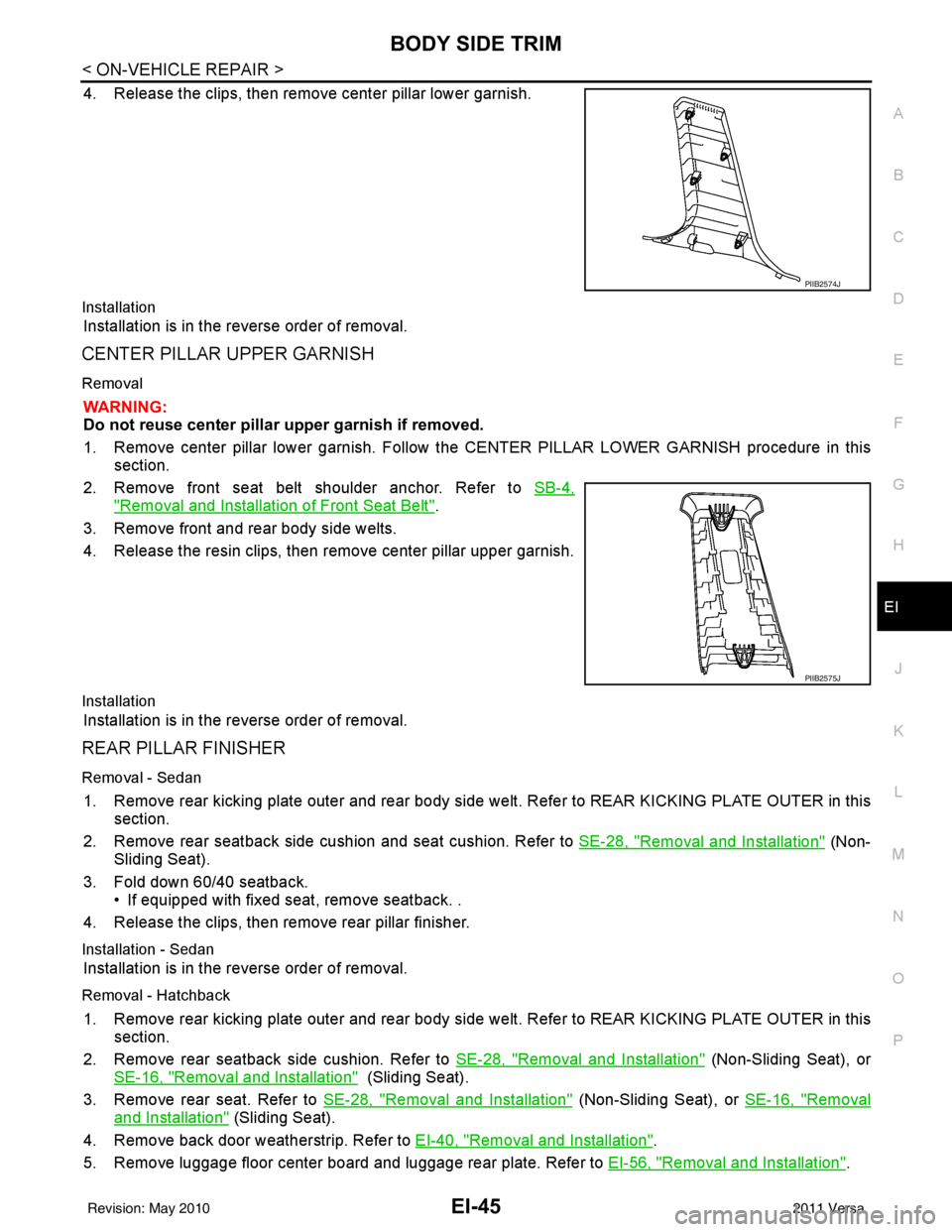
4. Release the clips, then remove center pillar lower garnish.
Installation
Installation is in the reverse order of removal.
CENTER PILLAR UPPER GARNISH
Removal
WARNING:
Do not reuse center pillar upper garnish if removed.
1. Remove center pillar lower garnish. Follow t he CENTER PILLAR LOWER GARNISH procedure in this
section.
2. Remove front seat belt shoulder anchor. Refer to SB-4,
"Removal and Installation of Front Seat Belt".
3. Remove front and rear body side welts.
4. Release the resin clips, then remove center pillar upper garnish.
Installation
Installation is in the reverse order of removal.
REAR PILLAR FINISHER
Removal - Sedan
1. Remove rear kicking plate outer and rear body side welt. Refer to REAR KICKING PLATE OUTER in this
section.
2. Remove rear seatback side cushion and seat cushion. Refer to SE-28, "
Removal and Installation" (Non-
Sliding Seat).
3. Fold down 60/40 seatback. • If equipped with fixed seat, remove seatback. .
4. Release the clips, then remove rear pillar finisher.
Installation - Sedan
Installation is in the reverse order of removal.
Removal - Hatchback
1. Remove rear kicking plate outer and rear body side welt. Refer to REAR KICKING PLATE OUTER in this
section.
2. Remove rear seatback side cushion. Refer to SE-28, "
Removal and Installation" (Non-Sliding Seat), or
SE-16, "
Removal and Installation" (Sliding Seat).
3. Remove rear seat. Refer to SE-28, "
Removal and Installation" (Non-Sliding Seat), or SE-16, "Removal
and Installation" (Sliding Seat).
4. Remove back door weatherstrip. Refer to EI-40, "
Removal and Installation".
5. Remove luggage floor center board and luggage rear plate. Refer to EI-56, "
Removal and Installation".
PIIB2574J
PIIB2575J
Revision: May 2010 2011 Versa
Page 2376 of 3787
EI-46
< ON-VEHICLE REPAIR >
BODY SIDE TRIM
6. Remove luggage side lower finisher. Refer to EI-56, "Removal and Installation".
7. Remove rear seat belt outer anchor bolt. Refer to SB-6, "
Removal and Installation of Rear Seat Belt".
8. Release the clips, then remove rear pillar finisher.
Installation - Hatchback
Installation is in the reverse order of removal.
Revision: May 2010 2011 Versa
Page 2377 of 3787
REAR PARCEL SHELF FINISHEREI-47
< ON-VEHICLE REPAIR >
C
DE
F
G H
J
K L
M A
B
EI
N
O P
REAR PARCEL SHELF FINISHER
Removal and InstallationINFOID:0000000005929573
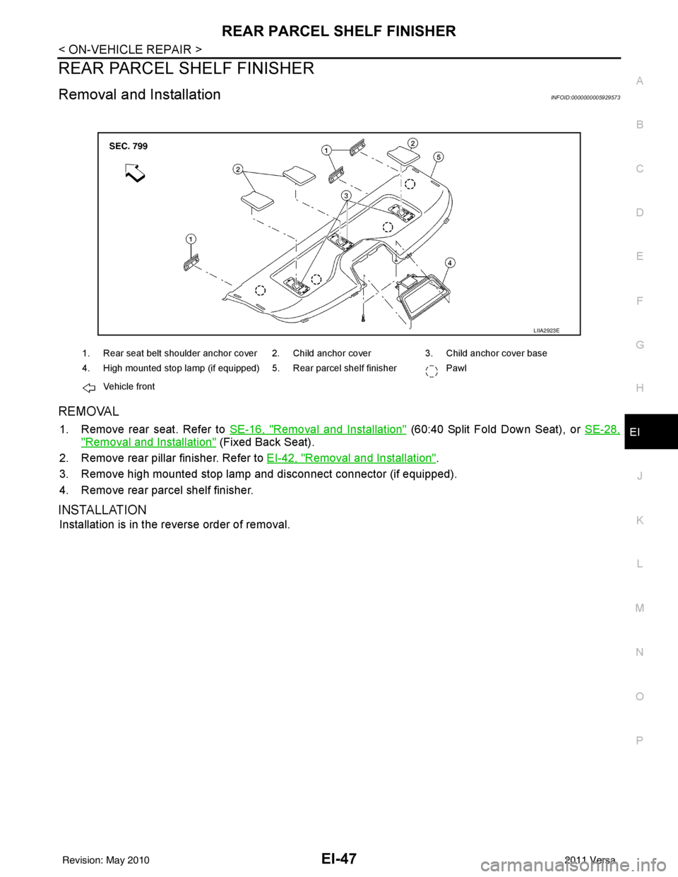
REMOVAL
1. Remove rear seat. Refer to SE-16, "Removal and Installation" (60:40 Split Fold Down Seat), or SE-28,
"Removal and Installation" (Fixed Back Seat).
2. Remove rear pillar finisher. Refer to EI-42, "
Removal and Installation".
3. Remove high mounted stop lamp and disconnect connector (if equipped).
4. Remove rear parcel shelf finisher.
INSTALLATION
Installation is in the reverse order of removal.
LIIA2923E
1. Rear seat belt shoulder anchor cover 2. Child anchor cover 3. Child anchor cover base
4. High mounted stop lamp (if equipped) 5. Rear parcel shelf finisher Pawl
Vehicle front
Revision: May 2010 2011 Versa
Page 2382 of 3787
EI-52
< ON-VEHICLE REPAIR >
HEADLINING
Removal and Installation - Hatchback
INFOID:0000000005929576
REMOVAL
1. Disconnect the negative and positive battery termi nals, then wait at least three minutes.
2. Remove front seat assembly RH/LH. Refer to SE-12, "
Removal and Installation".
3. Remove rear seat cushion and rear seatback. Refer to SE-16, "
Removal and Installation" (60:40 Split Fold
Down Seat), or SE-28, "
Removal and Installation" (Fixed Back Seat).
4. Remove front seat belt shoulder anchor RH/LH. Refer to SB-4, "
Removal and Installation of Front Seat
Belt".
5. Remove center console body assembly. Refer to IP-11
.
6. Remove front pillar garnish RH/LH. Refer to EI-42, "
Removal and Installation".
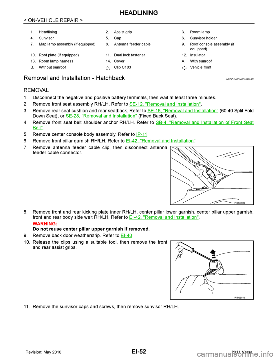
7. Remove antenna feeder cable clip, then disconnect antenna feeder cable connector.
8. Remove front and rear kicking plate inner RH/LH, center pillar lower garnish, center pillar upper garnish, front and rear body side welt RH/LH. Refer to EI-42, "
Removal and Installation".
WARNING:
Do not reuse center pillar upper garnish if removed.
9. Remove back door weatherstrip. Refer to EI-40
.
10. Release the clips using a suitable tool, then remove the front and rear assist grips.
11. Remove the sunvisor caps and screws, then remove sunvisor RH/LH.
1. Headlining 2. Assist grip 3. Room lamp
4. Sunvisor 5. Cap 6. Sunvisor holder
7. Map lamp assembly (if equipped) 8. Antenna feeder cable 9. Roof console assembly (if
equipped)
10. Roof plate (if equipped) 11. Dual lock fastener 12. Insulator
13. Room lamp harness 14. Cover A. With sunroof
B. Without sunroof Clip C103Vehicle front
PIIB2583J
PIIB2584J
Revision: May 2010 2011 Versa
Page 2384 of 3787
EI-54
< ON-VEHICLE REPAIR >
HEADLINING
Avoid headlining damage when installing by inserting rear clips first during assembly.
Removal and Installation - SedanINFOID:0000000005929577
REMOVAL
1. Disconnect the negative and positive battery terminals, then wait at least three minutes.
2. Remove front seat assembly RH/LH. Refer to SE-12, "
Removal and Installation".
3. Remove rear seat cushion and rear seatback. Refer to SE-22, "
Removal and Installation" (60:40 Split Fold
Down Seat), or SE-28, "
Removal and Installation" (Fixed Back Seat).
4. Remove front seat belt shoulder anchor RH/LH. Refer to SB-4, "
Removal and Installation of Front Seat
Belt".
5. Remove center console body assembly. Refer to IP-11
.
6. Remove front pillar garnish RH/LH. Refer to EI-42, "
Removal and Installation".
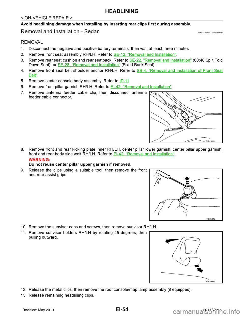
7. Remove antenna feeder cable clip, then disconnect antenna feeder cable connector.
8. Remove front and rear kicking plate inner RH/LH, center pillar lower garnish, center pillar upper garnish, front and rear body side welt RH/LH. Refer to EI-42, "
Removal and Installation".
WARNING:
Do not reuse center pillar upper garnish if removed.
9. Release the clips using a suitable tool, then remove the front and rear assist grips.
10. Remove the sunvisor caps and scr ews, then remove sunvisor RH/LH.
11. Remove sunvisor holders RH/LH by rotating 45 degrees, then pulling outward.
12. Release the metal clips, then remove the roof console/map lamp assembly (if equipped).
13. Release remaining headlining clips.
PIIB2583J
PIIB2584J
PIIB3982J
Revision: May 2010 2011 Versa