2011 NISSAN LATIO lock
[x] Cancel search: lockPage 849 of 3787

BR-2
< SERVICE INFORMATION >
PRECAUTIONS
SERVICE INFORMATION
PRECAUTIONS
Precaution for Supplemental Restraint System (SRS) "AIR BAG" and "SEAT BELT
PRE-TENSIONER"
INFOID:0000000005928385
The Supplemental Restraint System such as “A IR BAG” and “SEAT BELT PRE-TENSIONER”, used along
with a front seat belt, helps to reduce the risk or severity of injury to the driver and front passenger for certain
types of collision. This system includes seat belt switch inputs and dual stage front air bag modules. The SRS
system uses the seat belt switches to determine the front air bag deployment, and may only deploy one front
air bag, depending on the severity of a collision and w hether the front occupants are belted or unbelted.
Information necessary to service the system safely is included in the SRS and SB section of this Service Man-
ual.
WARNING:
• To avoid rendering the SRS inopera tive, which could increase the risk of personal injury or death in
the event of a collision which would result in air bag inflation, all maintenance must be performed by
an authorized NISSAN/INFINITI dealer.
• Improper maintenance, including incorrect removal and installation of the SRS can lead to personal
injury caused by unintent ional activation of the system. For re moval of Spiral Cable and Air Bag
Module, see the SRS section.
• Do not use electrical test equipmen t on any circuit related to the SRS unless instructed to in this
Service Manual. SRS wiring harn esses can be identified by yellow and/or orange harnesses or har-
ness connectors.
PRECAUTIONS WHEN USING POWER TOOLS (AIR OR ELECTRIC) AND HAMMERS
WARNING:
• When working near the Airbag Diagnosis Sensor Unit or other Airbag System sensors with the Igni-
tion ON or engine running, DO NOT use air or electri c power tools or strike near the sensor(s) with a
hammer. Heavy vibration could activate the sensor( s) and deploy the air bag(s), possibly causing
serious injury.
• When using air or electric power tools or hammers , always switch the Ignition OFF, disconnect the
battery, and wait at least 3 minu tes before performing any service.
Precaution Necessary for Steering W heel Rotation After Battery Disconnect
INFOID:0000000005928386
NOTE:
• This Procedure is applied only to models with Intelligent Key system and NATS (NISSAN ANTI-THEFT SYS-
TEM).
• Remove and install all control units after disconnecting both battery cables with the ignition knob in the
″LOCK ″ position.
• Always use CONSULT-III to perform self-diagnosis as a part of each function inspection after finishing work.
If DTC is detected, perform trouble diagnosis according to self-diagnostic results.
For models equipped with the Intelligent Key system and NATS, an electrically controlled steering lock mech-
anism is adopted on the key cylinder.
For this reason, if the battery is disconnected or if the battery is discharged, the steering wheel will lock and
steering wheel rotation will become impossible.
If steering wheel rotation is required when battery pow er is interrupted, follow the procedure below before
starting the repair operation.
OPERATION PROCEDURE
1. Connect both battery cables. NOTE:
Supply power using jumper cables if battery is discharged.
2. Use the Intelligent Key or mechanical key to turn the ignition switch to the ″ACC ″ position. At this time, the
steering lock will be released.
3. Disconnect both battery cables. The steering lock will remain released and the steering wheel can be rotated.
4. Perform the necessary repair operation.
Revision: May 2010 2011 Versa
Page 850 of 3787
PRECAUTIONSBR-3
< SERVICE INFORMATION >
C
DE
G H
I
J
K L
M A
B
BR
N
O P
5. When the repair work is completed, return the ignition switch to the ″LOCK ″ position before connecting
the battery cables. (At this time, the steering lock mechanism will engage.)
6. Perform a self-diagnosis check of al l control units using CONSULT-III.
Precaution for Brake SystemINFOID:0000000005928387
• Refill using recommended brake fluid. Refer to MA-14.
• Never reuse drained brake fluid.
• Be careful not to splash brake fluid on painted surface of body. If brake fluid is splashed on painted surfaces of body immediately wipe it off with cloth and then wash it away with water.
• To clean or wash all parts of master cylinder, disc brake caliper and wheel cylinder, use new brake fluid.
• Never use mineral oils such as gasoline or kerosene. They will ruin rubber parts of the hydraulic system.
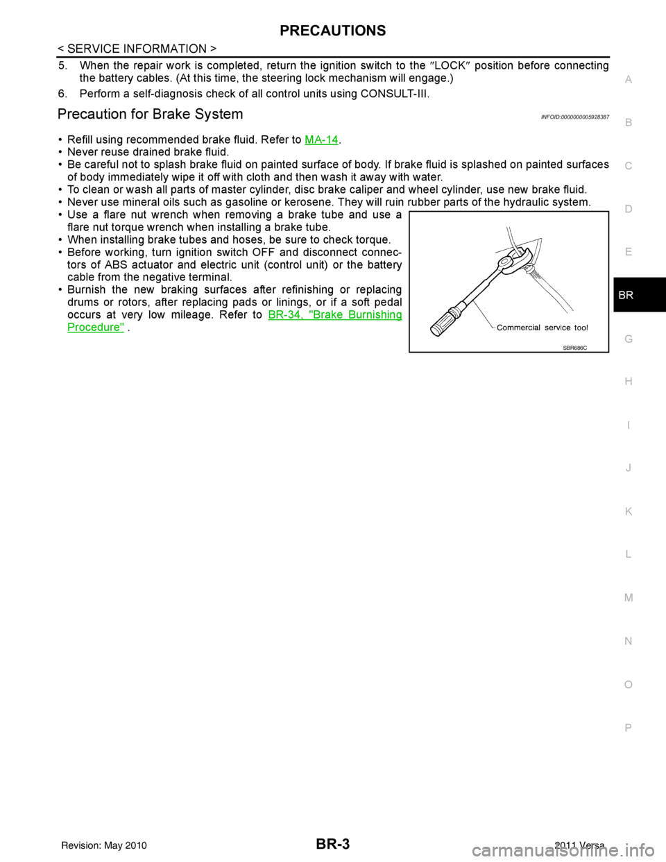
• Use a flare nut wrench when removing a brake tube and use a flare nut torque wrench when installing a brake tube.
• When installing brake tubes and hoses, be sure to check torque.
• Before working, turn igniti on switch OFF and disconnect connec-
tors of ABS actuator and electric unit (control unit) or the battery
cable from the negative terminal.
• Burnish the new braking surfaces after refinishing or replacing drums or rotors, after replacing p ads or linings, or if a soft pedal
occurs at very low mileage. Refer to BR-34, "
Brake Burnishing
Procedure" .
SBR686C
Revision: May 2010 2011 Versa
Page 854 of 3787
BRAKE PEDALBR-7
< SERVICE INFORMATION >
C
DE
G H
I
J
K L
M A
B
BR
N
O P
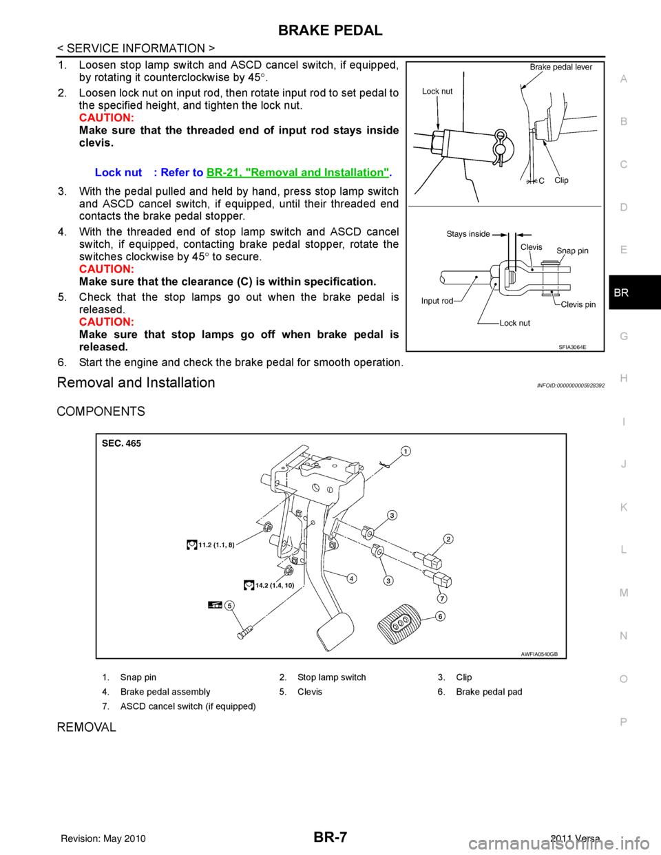
1. Loosen stop lamp switch and ASCD cancel switch, if equipped, by rotating it counterclockwise by 45 °.
2. Loosen lock nut on input rod, then rotate input rod to set pedal to the specified height, and tighten the lock nut.
CAUTION:
Make sure that the threaded end of input rod stays inside
clevis.
3. With the pedal pulled and held by hand, press stop lamp switch and ASCD cancel switch, if equipped, until their threaded end
contacts the brake pedal stopper.
4. With the threaded end of stop lamp switch and ASCD cancel switch, if equipped, contacting brake pedal stopper, rotate the
switches clockwise by 45 ° to secure.
CAUTION:
Make sure that the clearance (C) is within specification.
5. Check that the stop lamps go out when the brake pedal is released.
CAUTION:
Make sure that stop lamps go off when brake pedal is
released.
6. Start the engine and check the brake pedal for smooth operation.
Removal and InstallationINFOID:0000000005928392
COMPONENTS
REMOVAL
Lock nut : Refer to BR-21, "Removal and Installation".
SFIA3064E
1. Snap pin 2. Stop lamp switch3. Clip
4. Brake pedal assembly 5. Clevis6. Brake pedal pad
7. ASCD cancel switch (if equipped)
AWFIA0540GB
Revision: May 2010 2011 Versa
Page 859 of 3787
BR-12
< SERVICE INFORMATION >
BRAKE TUBE AND HOSE
• All tubes and hoses must be free from excessive bending, twisting and pulling.
• Make sure there is no interference with other part s when turning steering both clockwise and coun-
terclockwise.
• Brake tubes and hoses are an important safety part. Always disassemble the parts and retighten
their fittings, if a brake fluid leak is detected. Replace applicable part with a new one, if damaged part
is detected.
• Be careful not to splash brake fluid on painted areas; it may cause paint damage. If brake fluid is
splashed on painted surfaces of body , immediately wipe them with cloth and then wash it away with
water.
• Do not bend or twist brake hose sharply, or strongly pull it.
• When removing components, cover brake line connect ions so that dirt, dust, or other foreign mat-
ters do not get in.
• Refill using recommended brake fluid. Refer to MA-14, "
Fluids and Lubricants".
• Never reuse drained brake fluid.
Front Brake Tube and HoseINFOID:0000000005928397
REMOVAL
1. Drain brake fluid. Refer to BR-9, "Drain and Refill".
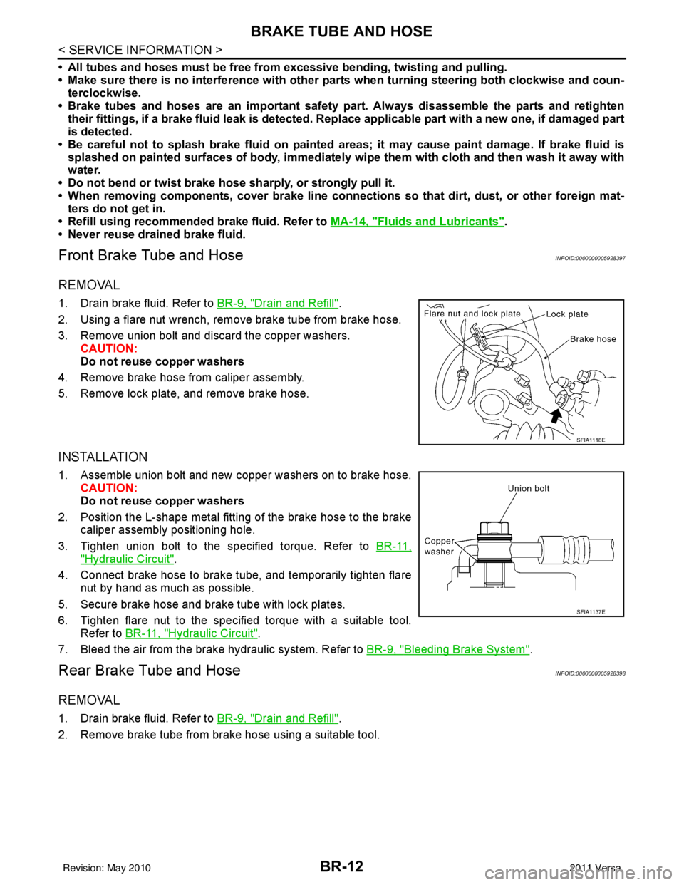
2. Using a flare nut wrench, remove brake tube from brake hose.
3. Remove union bolt and discard the copper washers. CAUTION:
Do not reuse copper washers
4. Remove brake hose from caliper assembly.
5. Remove lock plate, and remove brake hose.
INSTALLATION
1. Assemble union bolt and new copper washers on to brake hose. CAUTION:
Do not reuse copper washers
2. Position the L-shape metal fitting of the brake hose to the brake caliper assembly positioning hole.
3. Tighten union bolt to the specified torque. Refer to BR-11,
"Hydraulic Circuit".
4. Connect brake hose to brake tube, and temporarily tighten flare nut by hand as much as possible.
5. Secure brake hose and brake tube with lock plates.
6. Tighten flare nut to the specified torque with a suitable tool. Refer to BR-11, "
Hydraulic Circuit".
7. Bleed the air from the brake hydraulic system. Refer to BR-9, "
Bleeding Brake System".
Rear Brake Tube and HoseINFOID:0000000005928398
REMOVAL
1. Drain brake fluid. Refer to BR-9, "Drain and Refill".
2. Remove brake tube from brake hose using a suitable tool.
SFIA1118E
SFIA1137E
Revision: May 2010 2011 Versa
Page 860 of 3787
BRAKE TUBE AND HOSEBR-13
< SERVICE INFORMATION >
C
DE
G H
I
J
K L
M A
B
BR
N
O P
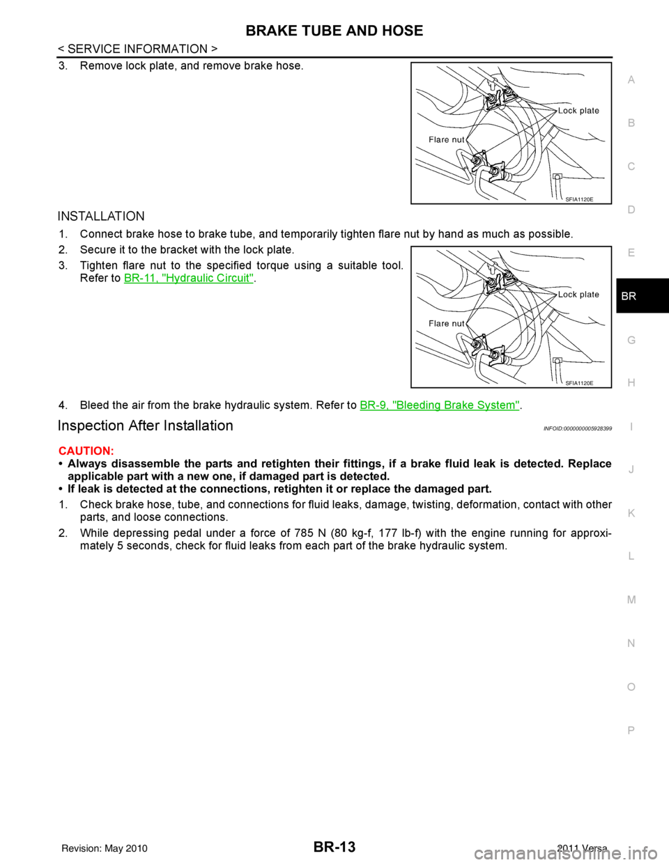
3. Remove lock plate, and remove brake hose.
INSTALLATION
1. Connect brake hose to brake tube, and temporaril y tighten flare nut by hand as much as possible.
2. Secure it to the bracket with the lock plate.
3. Tighten flare nut to the specified torque using a suitable tool. Refer to BR-11, "
Hydraulic Circuit".
4. Bleed the air from the brake hydraulic system. Refer to BR-9, "
Bleeding Brake System".
Inspection After InstallationINFOID:0000000005928399
CAUTION:
• Always disassemble the parts and retighten their fitti ngs, if a brake fluid leak is detected. Replace
applicable part with a new one, if damaged part is detected.
• If leak is detected at the connections, retighten it or replace the damaged part.
1. Check brake hose, tube, and connections for fluid leak s, damage, twisting, deformation, contact with other
parts, and loose connections.
2. While depressing pedal under a force of 785 N (80 kg-f, 177 lb-f) with the engine running for approxi- mately 5 seconds, check for fluid leaks from each part of the brake hydraulic system.
SFIA1120E
SFIA1120E
Revision: May 2010 2011 Versa
Page 865 of 3787
BR-18
< SERVICE INFORMATION >
BRAKE MASTER CYLINDER
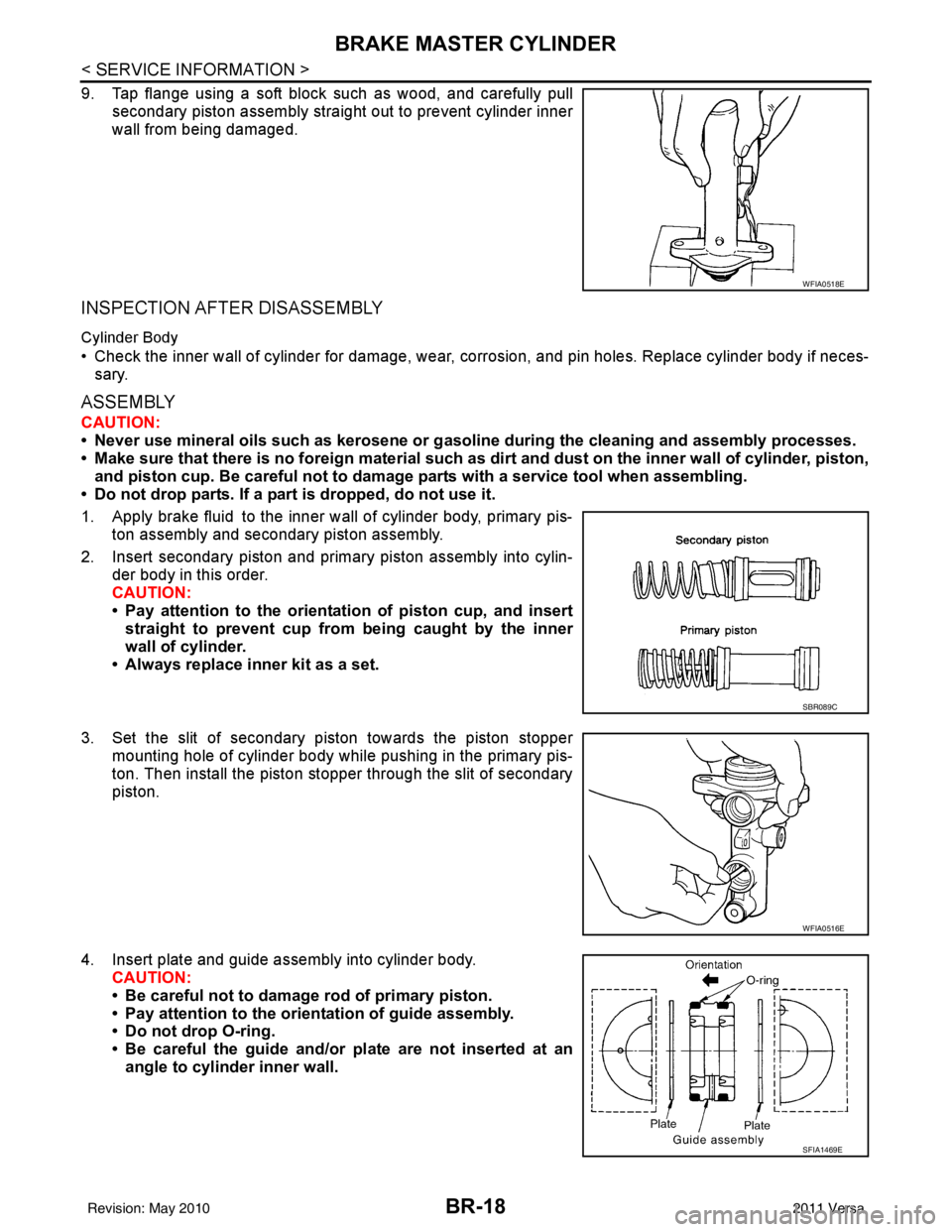
9. Tap flange using a soft block such as wood, and carefully pullsecondary piston assembly straight out to prevent cylinder inner
wall from being damaged.
INSPECTION AFTER DISASSEMBLY
Cylinder Body
• Check the inner wall of cylinder for damage, wear, corrosion, and pin holes. Replace cylinder body if neces-sary.
ASSEMBLY
CAUTION:
• Never use mineral oils such as kerosene or g asoline during the cleaning and assembly processes.
• Make sure that there is no foreign material such as dirt and dust on the inner wall of cylinder, piston,
and piston cup. Be careful not to damage parts with a service tool when assembling.
• Do not drop parts. If a part is dropped, do not use it.
1. Apply brake fluid to the inner wall of cylinder body, primary pis- ton assembly and secondary piston assembly.
2. Insert secondary piston and primary piston assembly into cylin- der body in this order.
CAUTION:
• Pay attention to the orientation of piston cup, and insert
straight to prevent cup from being caught by the inner
wall of cylinder.
• Always replace inner kit as a set.
3. Set the slit of secondary piston towards the piston stopper mounting hole of cylinder body while pushing in the primary pis-
ton. Then install the piston stopper through the slit of secondary
piston.
4. Insert plate and guide assembly into cylinder body. CAUTION:
• Be careful not to damage rod of primary piston.
• Pay attention to the orientation of guide assembly.
• Do not drop O-ring.
• Be careful the guide and/or plate are not inserted at an
angle to cylinder inner wall.
WFIA0518E
SBR089C
WFIA0516E
SFIA1469E
Revision: May 2010 2011 Versa
Page 869 of 3787
BR-22
< SERVICE INFORMATION >
BRAKE BOOSTER
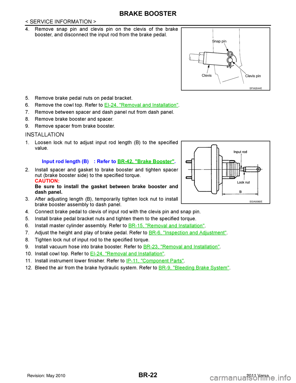
4. Remove snap pin and clevis pin on the clevis of the brakebooster, and disconnect the input rod from the brake pedal.
5. Remove brake pedal nuts on pedal bracket.
6. Remove the cowl top. Refer to EI-24, "
Removal and Installation".
7. Remove between spacer and dash panel nut from dash panel.
8. Remove brake booster and spacer.
9. Remove spacer from brake booster.
INSTALLATION
1. Loosen lock nut to adjust input rod length (B) to the specified value.
2. Install spacer and gasket to brake booster and tighten spacer nut (brake booster side) to the specified torque.
CAUTION:
Be sure to install the gasket between brake booster and
dash panel.
3. After adjusting length (B), temporarily tighten lock nut to install brake booster assembly to dash panel.
4. Connect brake pedal to clevis of input rod with the clevis pin and snap pin.
5. Install brake pedal bracket nuts and tighten them to the specified torque.
6. Install master cylinder assembly. Refer to BR-15, "
Removal and Installation".
7. Adjust the height and play of brake pedal. Refer to BR-6, "
Inspection and Adjustment".
8. Tighten lock nut of input rod to the specified torque.
9. Install vacuum hose into brake booster. Refer to BR-23, "
Removal and Installation".
10. Install cowl top. Refer to EI-24, "
Removal and Installation".
11. Install instrument lower finisher. Refer to IP-11, "
Component Parts".
12. Bleed the air from the brake hydraulic system. Refer to BR-9, "
Bleeding Brake System".
SFIA2044E
Input rod length (B) : Refer to BR-42, "Brake Booster".
SGIA0060E
Revision: May 2010 2011 Versa
Page 878 of 3787
FRONT DISC BRAKEBR-31
< SERVICE INFORMATION >
C
DE
G H
I
J
K L
M A
B
BR
N
O P
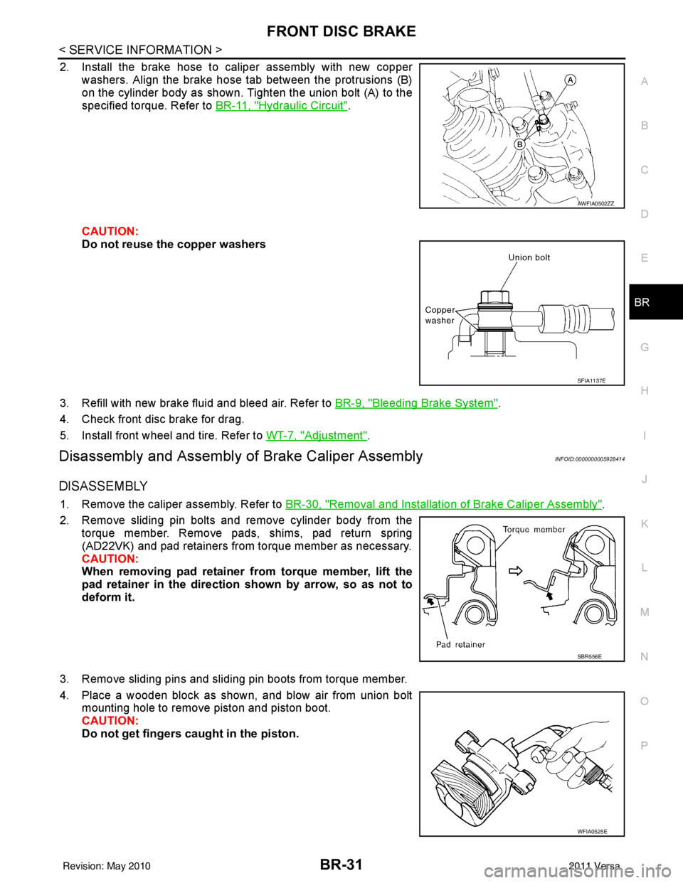
2. Install the brake hose to caliper assembly with new copper washers. Align the brake hose tab between the protrusions (B)
on the cylinder body as shown. Tighten the union bolt (A) to the
specified torque. Refer to BR-11, "
Hydraulic Circuit".
CAUTION:
Do not reuse the copper washers
3. Refill with new brake fluid and bleed air. Refer to BR-9, "
Bleeding Brake System".
4. Check front disc brake for drag.
5. Install front wheel and tire. Refer to WT-7, "
Adjustment".
Disassembly and Assembly of Brake Caliper AssemblyINFOID:0000000005928414
DISASSEMBLY
1. Remove the caliper assembly. Refer to BR-30, "Removal and Installation of Brake Caliper Assembly".
2. Remove sliding pin bolts and remove cylinder body from the torque member. Remove pads, shims, pad return spring
(AD22VK) and pad retainers from torque member as necessary.
CAUTION:
When removing pad retainer from torque member, lift the
pad retainer in the direction shown by arrow, so as not to
deform it.
3. Remove sliding pins and sliding pin boots from torque member.
4. Place a wooden block as shown, and blow air from union bolt mounting hole to remove piston and piston boot.
CAUTION:
Do not get fingers caught in the piston.
AWFIA0502ZZ
SFIA1137E
SBR556E
WFIA0525E
Revision: May 2010 2011 Versa