Page 983 of 3787

CL-2
< SERVICE INFORMATION >
PRECAUTIONS
SERVICE INFORMATION
PRECAUTIONS
Precaution for Supplemental Restraint System (SRS) "AIR BAG" and "SEAT BELT
PRE-TENSIONER"
INFOID:0000000005928987
The Supplemental Restraint System such as “A IR BAG” and “SEAT BELT PRE-TENSIONER”, used along
with a front seat belt, helps to reduce the risk or severity of injury to the driver and front passenger for certain
types of collision. This system includes seat belt switch inputs and dual stage front air bag modules. The SRS
system uses the seat belt switches to determine the front air bag deployment, and may only deploy one front
air bag, depending on the severity of a collision and w hether the front occupants are belted or unbelted.
Information necessary to service the system safely is included in the SRS and SB section of this Service Man-
ual.
WARNING:
• To avoid rendering the SRS inopera tive, which could increase the risk of personal injury or death in
the event of a collision which would result in air bag inflation, all maintenance must be performed by
an authorized NISSAN/INFINITI dealer.
• Improper maintenance, including incorrect removal and installation of the SRS can lead to personal
injury caused by unintent ional activation of the system. For re moval of Spiral Cable and Air Bag
Module, see the SRS section.
• Do not use electrical test equipmen t on any circuit related to the SRS unless instructed to in this
Service Manual. SRS wiring harn esses can be identified by yellow and/or orange harnesses or har-
ness connectors.
PRECAUTIONS WHEN USING POWER TOOLS (AIR OR ELECTRIC) AND HAMMERS
WARNING:
• When working near the Airbag Diagnosis Sensor Unit or other Airbag System sensors with the Igni-
tion ON or engine running, DO NOT use air or electri c power tools or strike near the sensor(s) with a
hammer. Heavy vibration could activate the sensor( s) and deploy the air bag(s), possibly causing
serious injury.
• When using air or electric power tools or hammers , always switch the Ignition OFF, disconnect the
battery, and wait at least 3 minu tes before performing any service.
Precaution Necessary for Steering W heel Rotation After Battery Disconnect
INFOID:0000000005928988
NOTE:
• This Procedure is applied only to models with Intelligent Key system and NATS (NISSAN ANTI-THEFT SYS-
TEM).
• Remove and install all control units after disconnecting both battery cables with the ignition knob in the
″LOCK ″ position.
• Always use CONSULT-III to perform self-diagnosis as a part of each function inspection after finishing work.
If DTC is detected, perform trouble diagnosis according to self-diagnostic results.
For models equipped with the Intelligent Key system and NATS, an electrically controlled steering lock mech-
anism is adopted on the key cylinder.
For this reason, if the battery is disconnected or if the battery is discharged, the steering wheel will lock and
steering wheel rotation will become impossible.
If steering wheel rotation is required when battery pow er is interrupted, follow the procedure below before
starting the repair operation.
OPERATION PROCEDURE
1. Connect both battery cables. NOTE:
Supply power using jumper cables if battery is discharged.
2. Use the Intelligent Key or mechanical key to turn the ignition switch to the ″ACC ″ position. At this time, the
steering lock will be released.
3. Disconnect both battery cables. The steering lock will remain released and the steering wheel can be rotated.
4. Perform the necessary repair operation.
Revision: May 2010 2011 Versa
Page 984 of 3787

PRECAUTIONSCL-3
< SERVICE INFORMATION >
DE
F
G H
I
J
K L
M A
B
CL
N
O P
5. When the repair work is completed, return the ignition switch to the ″LOCK ″ position before connecting
the battery cables. (At this time, the steering lock mechanism will engage.)
6. Perform a self-diagnosis check of al l control units using CONSULT-III.
Precaution for Procedure without Cowl Top CoverINFOID:0000000005928989
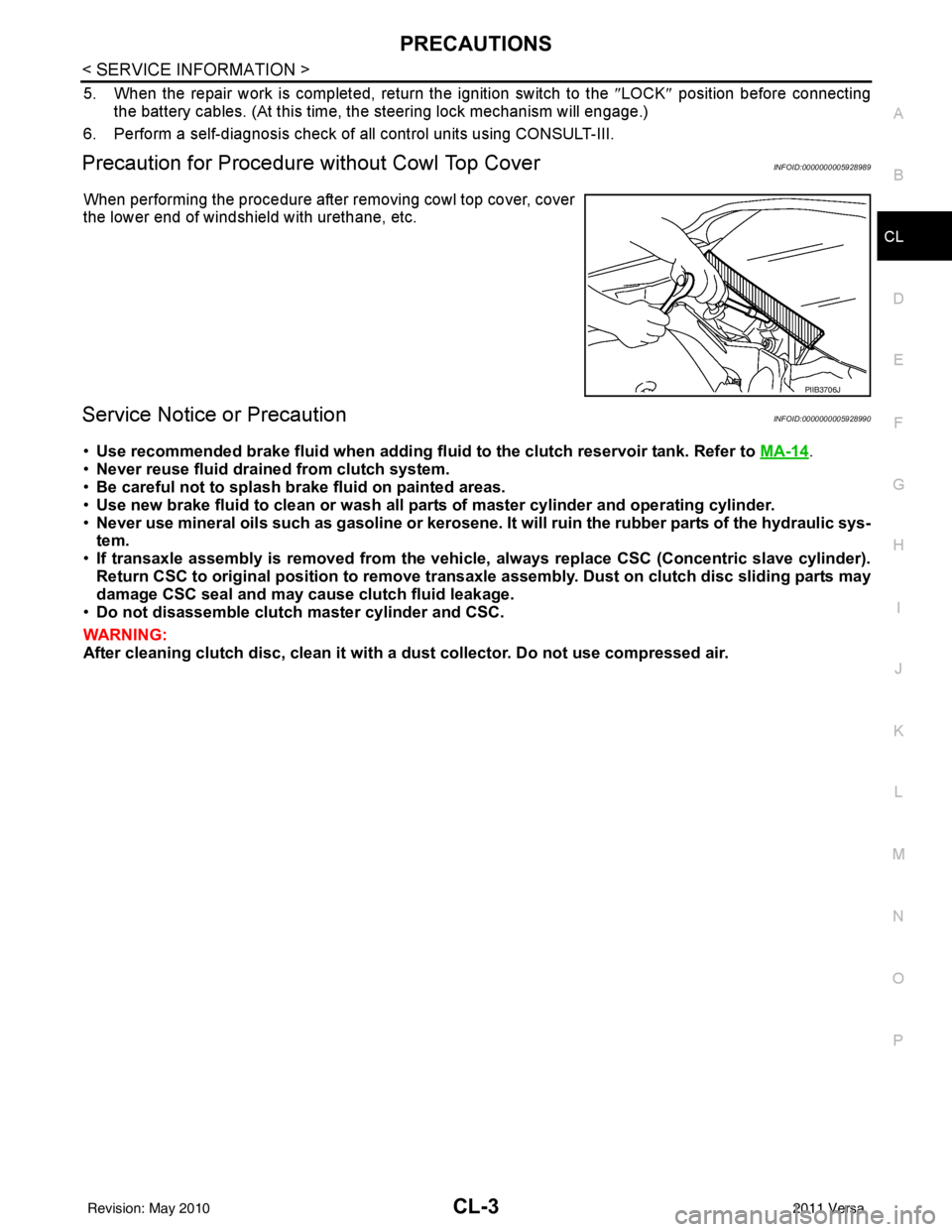
When performing the procedure after removing cowl top cover, cover
the lower end of windshield with urethane, etc.
Service Notice or PrecautionINFOID:0000000005928990
•Use recommended brake fluid when adding fluid to the clutch reservoir tank. Refer to MA-14.
• Never reuse fluid drained from clutch system.
• Be careful not to splash brake fluid on painted areas.
• Use new brake fluid to clean or wash all part s of master cylinder and operating cylinder.
• Never use mineral oils such as gasoline or kerosene. It will ruin the rubber parts of the hydraulic sys-
tem.
• If transaxle assembly is removed from the vehicle, always replace CSC (Con centric slave cylinder).
Return CSC to original position to remove transaxle assembly. Dust on clutch disc sliding parts may
damage CSC seal and may cause clutch fluid leakage.
• Do not disassemble clutch master cylinder and CSC.
WARNING:
After cleaning clutch disc, cl ean it with a dust collector. Do not use compressed air.
PIIB3706J
Revision: May 2010 2011 Versa
Page 987 of 3787

CL-6
< SERVICE INFORMATION >
CLUTCH PEDAL
CLUTCH PEDAL
On-vehicle Inspection and AdjustmentINFOID:0000000005928994
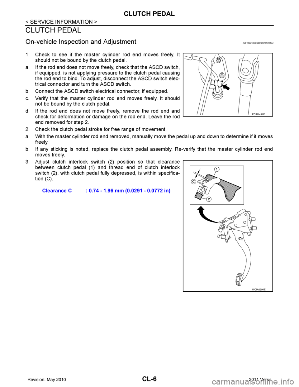
1. Check to see if the master cylinder rod end moves freely. Itshould not be bound by the clutch pedal.
a. If the rod end does not move freely, check that the ASCD switch, if equipped, is not applying pressure to the clutch pedal causing
the rod end to bind. To adjust, disconnect the ASCD switch elec-
trical connector and turn the ASCD switch.
b. Connect the ASCD switch electrical connector, if equipped.
c. Verify that the master cylinder rod end moves freely. It should not be bound by the clutch pedal.
d. If the rod end does not move freely, remove the rod end and check for deformation or damage on the rod end. Leave the rod
end removed for step 2.
2. Check the clutch pedal stroke for free range of movement.
a. With the master cylinder rod end removed, manually move the pedal up and down to determine if it moves
freely.
b. If any sticking is noted, replace the clutch pedal assembly. Re-verify that the master cylinder rod end
moves freely.
3. Adjust clutch interlock switch (2) position so that clearance between clutch pedal (1) and thread end of clutch interlock
switch (2), with clutch pedal fully depressed, is within specifica-
tion (C).
Clearance C : 0.74 - 1.96 mm (0.0291 - 0.0772 in)
PCIB1491E
WCIA0594E
Revision: May 2010 2011 Versa
Page 989 of 3787
CL-8
< SERVICE INFORMATION >
CLUTCH PEDAL
REMOVAL
1. Remove instrument lower finisher. Refer to IP-12, "Removal and Installation".
2. Disconnect clutch interlock switch and ASCD clutch switch harness connectors, if equipped.
3. Remove clutch switch harness clamp from clutch pedal assembly.
4. Disconnect master cylinder rod end from clutch pedal lever.
5. Remove clutch pedal assembly nuts, and then remove clutch pedal assembly.
INSPECTION AFTER REMOVAL
Check clutch pedal for bend, damage or a cracked weld. If bend, damage or a cracked weld is found, replace
clutch pedal assembly.
INSTALLATION
Installation is in the reverse order of removal.
• After installing the clutch switches, adjust the switch positions. Refer to CL-6, "
On-vehicle Inspection and
Adjustment".
1. Clutch pedal assembly 2. Lock nut 3. Clutch interlock switch
4. ASCD clutch switch 5. Lock nut
WCIA0596E
PCIB1491E
Revision: May 2010 2011 Versa
Page 990 of 3787

CLUTCH FLUIDCL-9
< SERVICE INFORMATION >
DE
F
G H
I
J
K L
M A
B
CL
N
O P
CLUTCH FLUID
Air Bleeding ProcedureINFOID:0000000005928996
CAUTION:
Do not spill clutch fluid onto painted surfaces. If it spills, wipe up immediately and wash the affected
area with water.
NOTE:
• Do not use a vacuum assist or any other type of power bleeder on this system. Use of a vacuum assist or power bleeder will not purge all the air from the system.
• Carefully monitor fluid level in reservoir tank during bleeding operation.
1. Fill master cylinder reservoir tank with new clutch fluid.
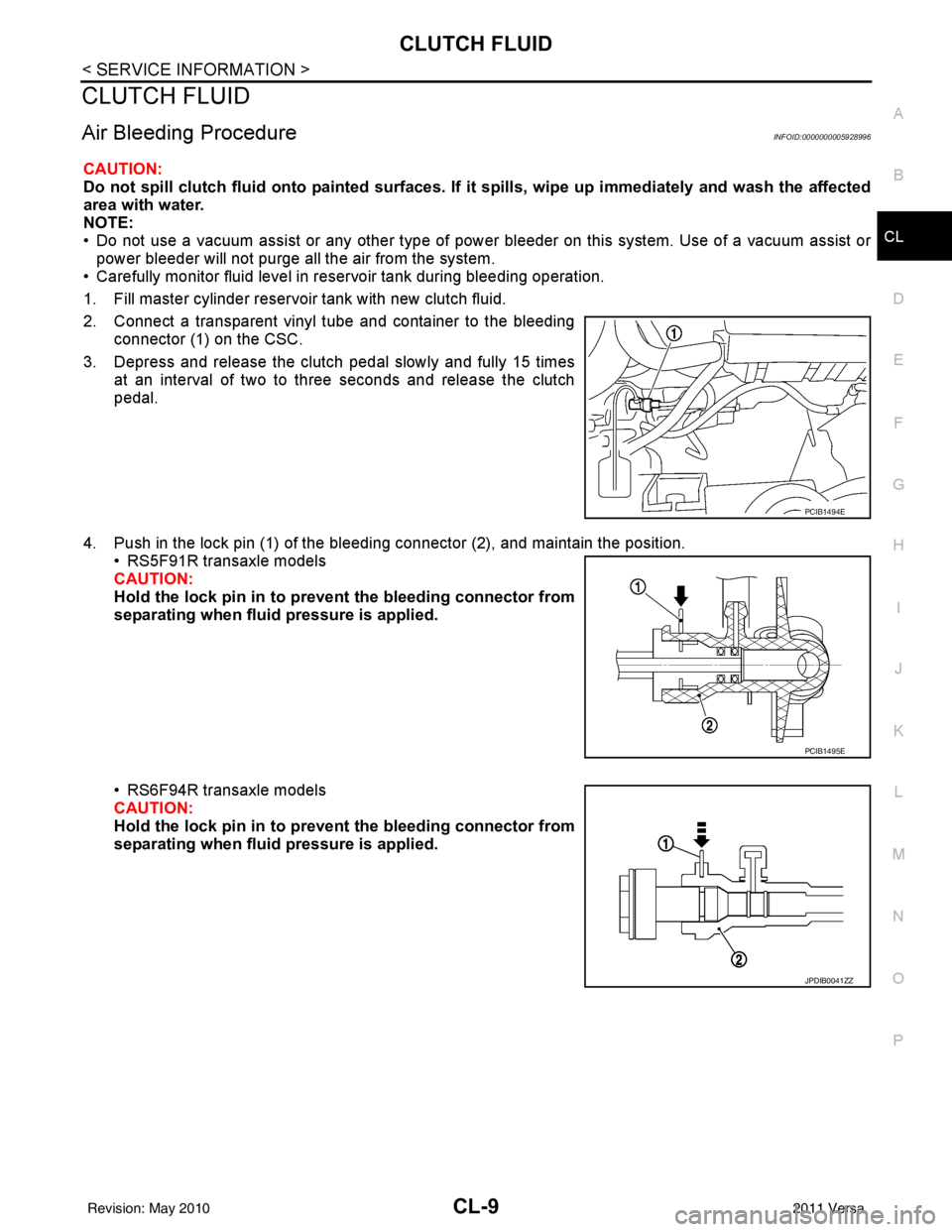
2. Connect a transparent vinyl tube and container to the bleeding connector (1) on the CSC.
3. Depress and release the clutch pedal slowly and fully 15 times at an interval of two to three seconds and release the clutch
pedal.
4. Push in the lock pin (1) of the bleeding connector (2), and maintain the position. • RS5F91R transaxle models
CAUTION:
Hold the lock pin in to preven t the bleeding connector from
separating when fluid pressure is applied.
• RS6F94R transaxle models
CAUTION:
Hold the lock pin in to preven t the bleeding connector from
separating when fluid pressure is applied.
PCIB1494E
PCIB1495E
JPDIB0041ZZ
Revision: May 2010 2011 Versa
Page 991 of 3787
CL-10
< SERVICE INFORMATION >
CLUTCH FLUID
5. Slide the clutch tube (1) in the direction of the arrow as shown tothe dimension (A). (For RS5F91R transaxle models)
2: bleeding connector
6. Slide bleeding connector (1) in the direction of the arrow as shown to the dimension (A). (For RS6F94R transaxle models)
2: clutch housing
7. Depress the clutch pedal soon and hold it, and then bleed air from the piping. wait for 5 seconds.
CAUTION:
Hold the clutch pedal down to prevent air from getting back
into the clutch system.
8. Return the clutch tube and lock pin to their original positions.
9. Release clutch pedal and wait for 5 seconds.
10. Repeat steps 3 to 8 until no bubbles are observed in the clutch fluid. Dimension (A) : 5 mm (0.20 in)
JPDIB0147ZZ
Dimension (A) : 10 mm (0.39 in)
JPDIB0042ZZ
Revision: May 2010
2011 Versa
Page 992 of 3787

CLUTCH MASTER CYLINDERCL-11
< SERVICE INFORMATION >
DE
F
G H
I
J
K L
M A
B
CL
N
O P
CLUTCH MASTER CYLINDER
Removal and InstallationINFOID:0000000005928997
REMOVAL
1. Remove the battery, battery tray and brackets. Refer to SC-5.
2. Remove the air cleaner and air duct. Refer to EM-25, "
Removal and Installation" (HR16DE models), EM-
135, "Removal and Installation" (MR18DE models).
3. Use one of the following methods to remove hose from master cylinder.
• Drain clutch fluid from reservoir tank and remove hose.
• Remove hose from master cylinder. Immediately plug hose and reservoir tank to prevent clutch fluid
from dripping.
CAUTION:
Do not spill clutch fluid onto painted surfaces. If it spills, wipe up immediately and wash the
affected area with water.
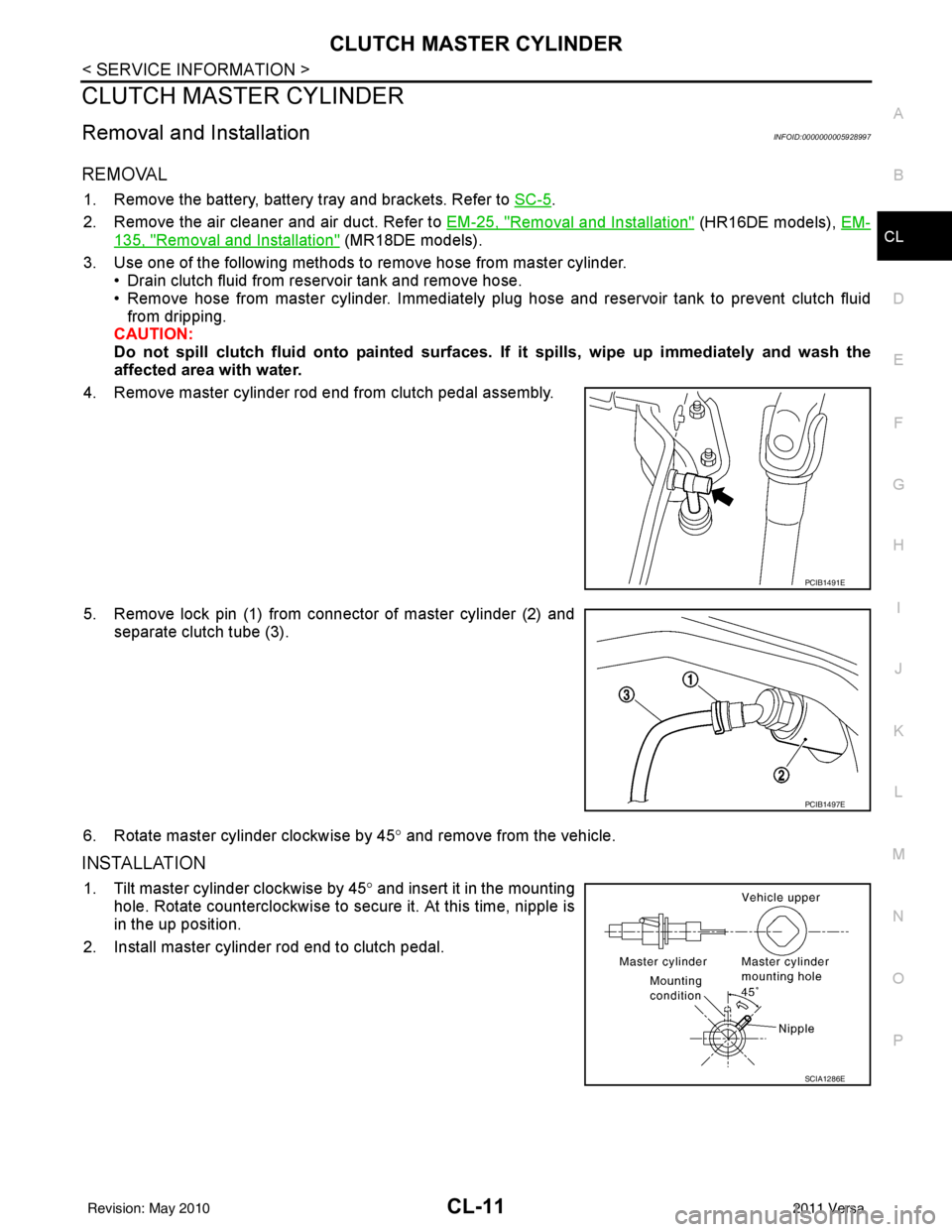
4. Remove master cylinder rod end from clutch pedal assembly.
5. Remove lock pin (1) from connector of master cylinder (2) and separate clutch tube (3).
6. Rotate master cylinder clockwise by 45 ° and remove from the vehicle.
INSTALLATION
1. Tilt master cylinder clockwise by 45° and insert it in the mounting
hole. Rotate counterclockwise to secure it. At this time, nipple is
in the up position.
2. Install master cylinder rod end to clutch pedal.
PCIB1491E
PCIB1497E
SCIA1286E
Revision: May 2010 2011 Versa
Page 993 of 3787
CL-12
< SERVICE INFORMATION >
CLUTCH MASTER CYLINDER
3. Install clutch tube (1) fully into connector of master cylinder (2).
4. Install lock pin (3) fully into connector of master cylinder (2).
5. Fill with new clutch fluid and bleed air from the system. Refer toCL-9
.
6. After completing this procedure, inspect clutch pedal operation. Refer to CL-6, "
On-vehicle Inspection and Adjustment".
7. Install the air cleaner and air duct. Refer to EM-25, "
Removal
and Installation" (HR16DE models), EM-135, "Removal and
Installation" (MR18DE models).
8. Install the battery. Refer to SC-5
.PCIB1500E
Revision: May 2010 2011 Versa