2011 NISSAN LATIO brakes
[x] Cancel search: brakesPage 890 of 3787

BRC-1
BRAKES
C
DE
G H
I
J
K L
M
SECTION BRC
A
B
BRC
N
O P
CONTENTS
BRAKE CONTROL SYSTEM
ABS
SERVICE INFORMATION .. ..........................
3
PRECAUTIONS .............................................. .....3
Precaution for Supplemental Restraint System
(SRS) "AIR BAG" and "SEAT BELT PRE-TEN-
SIONER" ............................................................. ......
3
Precaution for Brake System ....................................3
Precaution for Brake Control .....................................4
Precaution for CAN System ................................ ......4
PREPARATION ...................................................5
Special Service Tool ........................................... ......5
Commercial Service Tool ..........................................5
SYSTEM DESCRIPTION .....................................6
System Component ............................................. ......6
ABS Function ............................................................6
EBD Function ............................................................6
Fail-Safe Function .....................................................6
Hydraulic Circuit Diagram .........................................7
CAN COMMUNICATION ................................ .....8
System Description ............................................. ......8
TROUBLE DIAGNOSIS ......................................9
How to Perform Trouble Diagnosis for Quick and
Accurate Repair ........................................................
9
Component Parts and Harness Connector Loca-
tion ...................................................................... ....
12
Schematic ...............................................................13
Wiring Diagram - ABS - ...........................................14
Basic Inspection .................................................. ....17
Warning Lamp and Indicator Timing .......................18
Control Unit Input/Output Signal Standard ..............18
CONSULT-III Function (ABS) .................................19
TROUBLE DIAGNOSIS FOR SELF-DIAG-
NOSTIC ITEMS ..................................................
25
Wheel Sensor System .............................................25
ABS Control Unit Inspection ....................................26
Solenoid Valve System Inspection ...................... ....26
Actuator Motor, Motor Relay, and Circuit Inspec-
tion ....................................................................... ....
27
ABS Control Unit Power and Ground Systems In-
spection ...................................................................
28
CAN Communication System Inspection .................29
TROUBLE DIAGNOSES FOR SYMPTOMS .....30
ABS Works Frequently ............................................30
Unexpected Pedal Action ........................................30
Long Stopping Distance ..........................................31
ABS Does Not Work ................................................31
Pedal Vibration or ABS Operation Noise .................31
WHEEL SENSORS ...........................................33
Removal and Installation ..................................... ....33
SENSOR ROTOR ..............................................35
Removal and Installation .........................................35
ACTUATOR AND ELECTRIC UNIT (ASSEM-
BLY) ..................................................................
36
Removal and Installation .........................................36
VDC/TCS/ABS
SERVICE INFORMATION .. .........................
38
PRECAUTIONS .................................................38
Precaution for Supplemental Restraint System
(SRS) "AIR BAG" and "SEAT BELT PRE-TEN-
SIONER" ............................................................. ....
38
Precautions Necessary for Steering Wheel Rota-
tion after Battery Disconnect ...................................
38
Precaution for Brake System ...................................39
Precaution for Brake Control ...................................39
Precaution for CAN System .....................................40
PREPARATION .................................................41
Special Service Tool ................................................41
Commercial Service Tool ........................................41
SYSTEM DESCRIPTION ..................................42
Revision: May 2010 2011 Versa
Page 1008 of 3787
![NISSAN LATIO 2011 Service Repair Manual CO-8
< SYMPTOM DIAGNOSIS >[HR16DE]
OVERHEATING CAUSE ANALYSIS
Except cool-
ing system
parts mal-
function—
Overload on engine Abusive driving
High engine rpm under no
load
Driving in low gear for NISSAN LATIO 2011 Service Repair Manual CO-8
< SYMPTOM DIAGNOSIS >[HR16DE]
OVERHEATING CAUSE ANALYSIS
Except cool-
ing system
parts mal-
function—
Overload on engine Abusive driving
High engine rpm under no
load
Driving in low gear for](/manual-img/5/57357/w960_57357-1007.png)
CO-8
< SYMPTOM DIAGNOSIS >[HR16DE]
OVERHEATING CAUSE ANALYSIS
Except cool-
ing system
parts mal-
function—
Overload on engine Abusive driving
High engine rpm under no
load
Driving in low gear for ex-
tended time
Driving at extremely high
speed
Power train system mal-
function
—
Installed improper size
wheels and tires
Dragging brakes
Improper ignition timing
Blocked or restricted air
flow Blocked bumper
Installed front bumper fas-
cia cover
—
Blocked radiator grille Mud contamination or paper
clogging
Blocked radiator Blocked air flow
Blocked condenser
Installed large fog lamp
Symptom
Check items
Revision: May 2010 2011 Versa
Page 1033 of 3787
![NISSAN LATIO 2011 Service Repair Manual OVERHEATING CAUSE ANALYSISCO-33
< SERVICE INFORMATION > [MR18DE]
C
D
E
F
G H
I
J
K L
M A
CO
NP
O
Except cool-
ing system
parts mal-
function —
Overload on engine Abusive driving
High engine rpm und NISSAN LATIO 2011 Service Repair Manual OVERHEATING CAUSE ANALYSISCO-33
< SERVICE INFORMATION > [MR18DE]
C
D
E
F
G H
I
J
K L
M A
CO
NP
O
Except cool-
ing system
parts mal-
function —
Overload on engine Abusive driving
High engine rpm und](/manual-img/5/57357/w960_57357-1032.png)
OVERHEATING CAUSE ANALYSISCO-33
< SERVICE INFORMATION > [MR18DE]
C
D
E
F
G H
I
J
K L
M A
CO
NP
O
Except cool-
ing system
parts mal-
function —
Overload on engine Abusive driving
High engine rpm under no
load
Driving in low gear for ex-
tended time
Driving at extremely high
speed
Power train system mal-
function
—
Installed improper size
wheels and tires
Dragging brakes
Improper ignition timing
Blocked or restricted air
flow Blocked bumper
Installed front bumper fas-
cia cover
—
Blocked radiator grille Mud contamination or paper
clogging
Blocked radiator Blocked air flow
Blocked condenser
Installed large fog lamp
Symptom
Check items
Revision: May 2010 2011 Versa
Page 1066 of 3787
![NISSAN LATIO 2011 Service Repair Manual PRECAUTIONSCVT-11
< SERVICE INFORMATION > [RE0F08B]
D
E
F
G H
I
J
K L
M A
B
CVT
N
O P
• When connecting or disconnecting pin connectors into or
from TCM, take care not to damage pin terminals (bend NISSAN LATIO 2011 Service Repair Manual PRECAUTIONSCVT-11
< SERVICE INFORMATION > [RE0F08B]
D
E
F
G H
I
J
K L
M A
B
CVT
N
O P
• When connecting or disconnecting pin connectors into or
from TCM, take care not to damage pin terminals (bend](/manual-img/5/57357/w960_57357-1065.png)
PRECAUTIONSCVT-11
< SERVICE INFORMATION > [RE0F08B]
D
E
F
G H
I
J
K L
M A
B
CVT
N
O P
• When connecting or disconnecting pin connectors into or
from TCM, take care not to damage pin terminals (bend or
break).
When connecting pin connectors make sure that there are not
any bends or breaks on TCM pin terminal.
• Before replacing TCM, perform TCM input/output signal
inspection and make sure whether TCM functions properly or
not. CVT-46, "
TCM Terminal and Reference Value".
• After performing each TROUBL E DIAGNOSIS, perform “DTC
Confirmation Procedure”.
If the repair is completed the DTC should not be displayed in
the “DTC Confirmation Procedure”.
• Always use the specified br and of CVT fluid. Refer to MA-14, "
Flu-
ids and Lubricants".
• Use lint-free paper, not cloth rags, during work.
• After replacing the CVT fluid, dispose of the waste oil using the methods prescribed by law, ordinance, etc.
Service Notice or PrecautionINFOID:0000000005928726
CVT FLUID COOLER SERVICE
If CVT fluid contains friction material (clutches, brakes , etc.), or if an CVT is replaced, inspect and clean the
CVT fluid cooler mounted in the radiator or replace the radiator. Flush cooler lines using cleaning solvent and
compressed air after repair. For CVT fluid cooler cleaning procedure, refer to CVT-15, "
CVT Fluid Cooler
Cleaning". For radiator replacement, refer to CO-40.
OBD-II SELF-DIAGNOSIS
• CVT self-diagnosis is performed by the TCM in combination with the ECM. The results can be read through
the blinking pattern of the malfunction indi cator lamp (MIL). Refer to the table on CVT-48, "
CONSULT-III
Function (TRANSMISSION)" for the indicator used to display each self-diagnostic result.
• The self-diagnostic results indicated by the MIL are automatically stored in both the ECM and TCM memo- ries.
Always perform the procedure on CVT-27, "
OBD-II Diagnostic Trouble Code (DTC)" to complete the
repair and avoid unnecessary blinking of the MIL.
For details of OBD-II, refer to EC-541, "
Introduction".
• Certain systems and components, especially those re lated to OBD, may use the new style slide-lock-
ing type harness connector. For description and how to disconnect, refer to PG-65
.
ATFTEMP COUNT Conversion Table INFOID:0000000005928727
SEF291H
MEF040DA
SEF217U
Revision: May 2010 2011 Versa
Page 2647 of 3787

NOISE, VIBRATION AND HARSHNESS (NVH) TROUBLESHOOTINGFAX-5
< SERVICE INFORMATION >
CEF
G H
I
J
K L
M A
B
FA X
N
O P
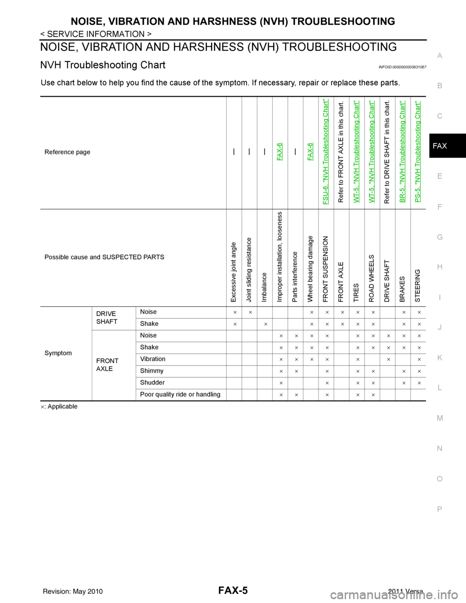
NOISE, VIBRATION AND HARSHN ESS (NVH) TROUBLESHOOTING
NVH Troubleshooting ChartINFOID:0000000005931067
Use chart below to help you find the cause of the symptom. If necessary, repair or replace these parts.
×: ApplicableReference page
—
—
—
FAX-6—
FAX-6
FSU-6, "
NVH Troubleshooting Chart
"
Refer to FRONT AXLE in this chart.
WT-5, "
NVH Troubleshooting Chart
"
WT-5, "
NVH Troubleshooting Chart
"
Refer to DRIVE SHAFT in this chart. BR-5, "
NVH Troubleshooting Chart
"
PS-5, "
NVH Troubleshooting Chart
"
Possible cause and SUSPECTED PARTS
Excessive joint angle
Joint sliding resistance
Imbalance
Improper installation, looseness
Parts interference
Wheel bearing damage
FRONT SUSPENSION
FRONT AXLE
TIRES
ROAD WHEELS
DRIVE SHAFT
BRAKES
STEERING
SymptomDRIVE
SHAFT
Noise
××××××× ××
Shake × × ××××× ××
FRONT
AXLE Noise
×××× ×××××
Shake ×××× ×××××
Vibration ×××××××
Shimmy ×××××××
Shudder × × ×× ××
Poor quality ride or handling ×××××
Revision: May 2010 2011 Versa
Page 2691 of 3787

FSU-6
< SERVICE INFORMATION >
NOISE, VIBRATION AND HARSHNESS (NVH) TROUBLESHOOTING
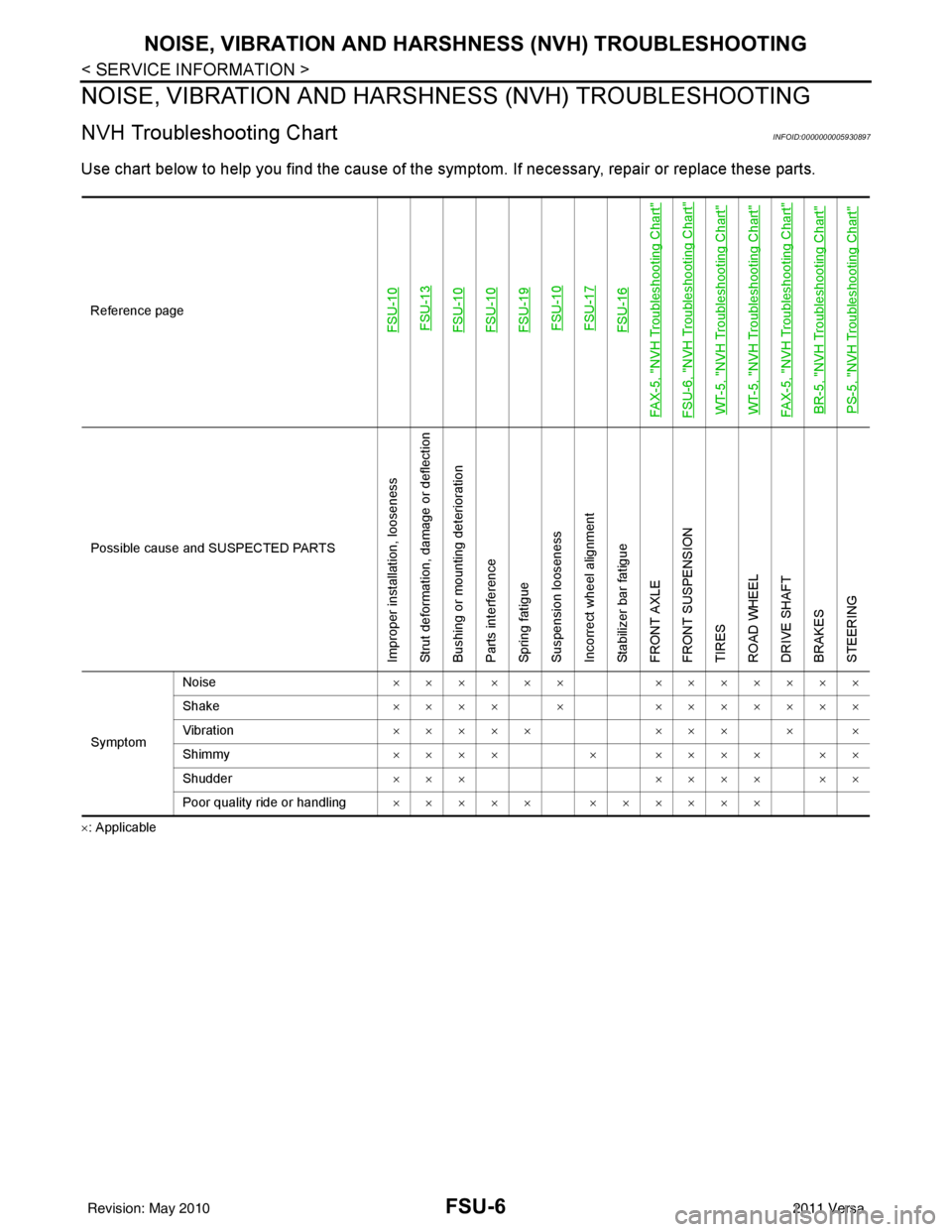
NOISE, VIBRATION AND HARSHNESS (NVH) TROUBLESHOOTING
NVH Troubleshooting ChartINFOID:0000000005930897
Use chart below to help you find the cause of the symp tom. If necessary, repair or replace these parts.
×: ApplicableReference page
FSU-10
FSU-13FSU-10FSU-10FSU-19 FSU-10 FSU-17FSU-16
FAX-5, "
NVH Troubleshooting Chart
"
FSU-6, "
NVH Troubleshooting Chart
"
WT-5, "
NVH Troubleshooting Chart
"
WT-5, "
NVH Troubleshooting Chart
"
FAX-5, "
NVH Troubleshooting Chart
"
BR-5, "
NVH Troubleshooting Chart
"
PS-5, "
NVH Troubleshooting Chart
"
Possible cause an d SUSPECTED PARTS
Improper installation, looseness
Strut deformation, damage or deflection
Bushing or mounting deterioration
Parts interference
Spring fatigue
Suspension looseness
Incorrect wheel alignment
Stabilizer bar fatigue
FRONT AXLE
FRONT SUSPENSION
TIRES
ROAD WHEEL
DRIVE SHAFT
BRAKES
STEERING
SymptomNoise
×××××× ×××××××
Shake ×××× × ×××××××
Vibration ××××× ××× × ×
Shimmy ×××× × ×××× ××
Shudder ××× ×××× ××
Poor quality ride or handling ××××× ××××××
Revision: May 2010 2011 Versa
Page 3179 of 3787

MA-8
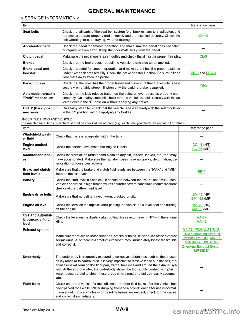
< SERVICE INFORMATION >
GENERAL MAINTENANCE
UNDER THE HOOD AND VEHICLE
The maintenance items listed here should be checked periodically (e.g. each time you check the engine oil or refuel).
Seat beltsCheck that all parts of the seat belt system (e.g. buckles, anchors, adjusters and
retractors) operate properly and smoothly and are installed securely. Check the
belt webbing for cuts, fraying, wear or damage. MA-49
Accelerator pedal
Check the pedal for smooth operation and make sure the pedal does not catch
or require uneven effort. Keep the floor mats away from the pedal. —
Clutch pedal Make sure the pedal operates smoothly and check that it has the proper free play. CL-6
BrakesCheck that the brake does not pull the vehicle to one side when applied. —
Brake pedal and
booster Check the pedal for smooth operation and make sure it has the proper distance
under it when depressed fully. Check the brake booster function. Be sure to keep
floor mats away from the pedal. BR-6
and
BR-20
Parking brake Check that the lever has the proper travel and make sure that the vehicle is held
securely on a fairly steep hill when only the parking brake is applied. PB-5
Automatic transaxle
“Park” mechanismCheck that the lock release button on the selector lever operates properly and
smoothly. On a fairly steep hill check that the vehicle is held securely with the se-
lector lever in the “P” position without applying any brakes. —
CVT P (Park) position
mechanism On a fairly steep hill check that the vehicle is held securely with the selector lever
in the “P” position without applying any brakes.
—
Item
Reference page
ItemReference page
Windshield wash-
er fluid Check that there is adequate fluid in the tank.
—
Engine coolant
level Check the coolant level when the engine is cold. CO-11
(HR)
CO-36
(MR)
Radiator and hos-
es Check the front of the radiator and clean off any dirt, insects, leaves, etc., that may
have accumulated. Make sure the radiator hoses have no cracks, deformation, de-
terioration or loose connections.
—
Brake and clutch
fluid levels Make sure that the brake and clutch fluid levels are between the “MAX” and “MIN”
lines on the reservoirs.
BR-9
Battery
Check the fluid level in each cell. It should be between the “MAX” and “MIN” lines.
Vehicles operated in high temperatures or under severe conditions require frequent
checks of the battery fluid level. —
Engine drive belts Make sure that no belt is frayed, worn, cracked or oily. EM-13
(HR)
EM-132
(MR)
Engine oil level Check the level on the dipstick after parking the vehicle on a level spot and turning
off the engine. MA-20
(HR)
MA-30
(MR)
CVT and Automat-
ic transaxle fluid
level Check the level on the dipstick after putting the selector lever in “P” with the engine
idling.
MA-37
MA-42
Exhaust system
Make sure there are no loose supports, cracks or holes. If the sound of the exhaust
seems unusual or there is a smell of exhaust fumes, immediately locate the trouble
and correct it. MA-37, "EXHAUST SYS-
TEM : Checking Exhaust
System HR16DE", MA-37,
"EXHAUST SYSTEM :
Checking Exhaust System
MR18DE"
Underbody
The underbody is frequently exposed to corrosive substances such as those used
on icy roads or to control dust. It is very important to remove these substances, oth-
erwise rust will form on the floor pan, frame, fuel lines and around the exhaust sys-
tem. At the end of winter, the underbody should be thoroughly flushed with plain
water, being careful to clean those areas where mud and dirt can easily accumu-
late. —
Fluid leaks Check under the vehicle for fuel, oil, water or other fluid leaks after the vehicle has
been parked for a while. Water dripping from the air conditioner after use is normal.
If you should notice any leaks or gasoline fumes are evident, check for the cause
and correct it immediately. —
Revision: May 2010
2011 Versa
Page 3413 of 3787

PB-1
BRAKES
C
DE
G H
I
J
K L
M
SECTION PB
A
B
PB
N
O P
CONTENTS
PARKING BRAKE SYSTEM
SERVICE INFORMATION .. ..........................2
PRECAUTIONS .............................................. .....2
Precaution for Supplemental Restraint System
(SRS) "AIR BAG" and "SEAT BELT PRE-TEN-
SIONER" ............................................................. ......
2
Precaution Necessary for Steering Wheel Rota-
tion After Battery Disconnect ............................... ......
2
PREPARATION ...................................................4
Commercial Service Tool .................................... .....4
PARKING BRAKE CONTROL ...........................5
On-Vehicle Service ...................................................5
Component ...............................................................6
Removal and Installation ..........................................6
SERVICE DATA AND SPECIFICATIONS
(SDS) ..................................................................
8
Parking Brake Control ..............................................8
Revision: May 2010 2011 Versa