2011 NISSAN LATIO brakes
[x] Cancel search: brakesPage 327 of 3787
AT-310
< SERVICE INFORMATION >
REPAIR FOR COMPONENT PARTS
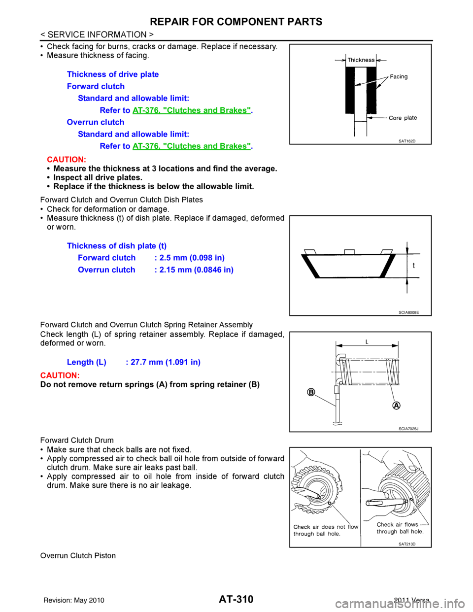
• Check facing for burns, cracks or damage. Replace if necessary.
• Measure thickness of facing.CAUTION:
• Measure the thickness at 3 locations and find the average.
• Inspect all drive plates.
• Replace if the thickness is below the allowable limit.
Forward Clutch and Overrun Clutch Dish Plates
• Check for deformation or damage.
• Measure thickness (t) of dish pl ate. Replace if damaged, deformed
or worn.
Forward Clutch and Overrun Clutch Spring Retainer Assembly
Check length (L) of spring retainer assembly. Replace if damaged,
deformed or worn.
CAUTION:
Do not remove return springs (A ) from spring retainer (B)
Forward Clutch Drum
• Make sure that check balls are not fixed.
• Apply compressed air to check ball oil hole from outside of forward
clutch drum. Make sure air leaks past ball.
• Apply compressed air to oil hole from inside of forward clutch drum. Make sure there is no air leakage.
Overrun Clutch Piston
Thickness of drive plate
Forward clutch
Standard and allowable limit: Refer to AT-376, "
Clutches and Brakes".
Overrun clutch Standard and allowable limit: Refer to AT-376, "
Clutches and Brakes".SAT162D
Thickness of dish plate (t)
Forward clutch : 2.5 mm (0.098 in)
Overrun clutch : 2.15 mm (0.0846 in)
SCIA8008E
Length (L) : 27.7 mm (1.091 in)
SCIA7025J
SAT213D
Revision: May 2010 2011 Versa
Page 330 of 3787
REPAIR FOR COMPONENT PARTSAT-313
< SERVICE INFORMATION >
DE
F
G H
I
J
K L
M A
B
AT
N
O P
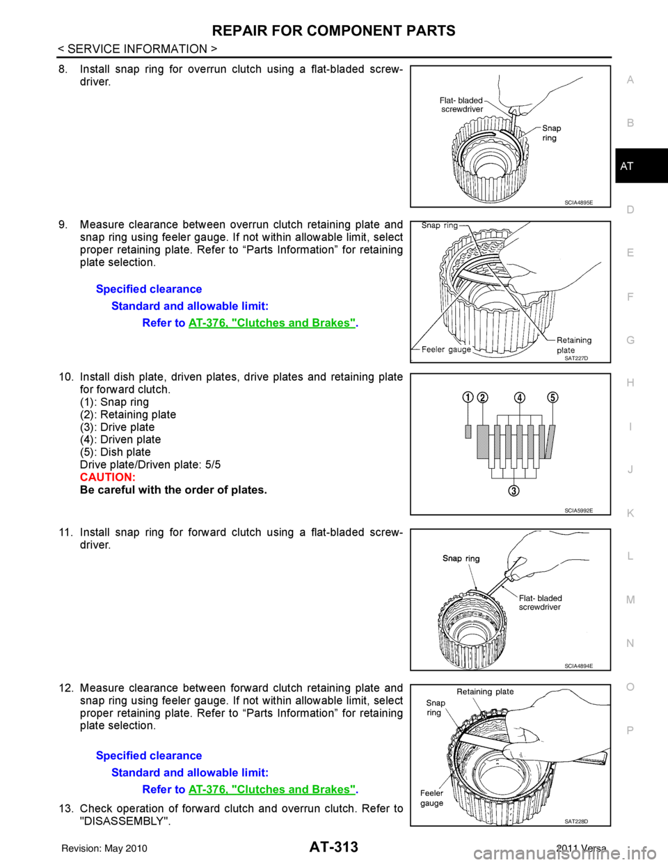
8. Install snap ring for overrun clutch using a flat-bladed screw- driver.
9. Measure clearance between overrun clutch retaining plate and snap ring using feeler gauge. If not within allowable limit, select
proper retaining plate. Refer to “Parts Information” for retaining
plate selection.
10. Install dish plate, driven plates, drive plates and retaining plate for forward clutch.
(1): Snap ring
(2): Retaining plate
(3): Drive plate
(4): Driven plate
(5): Dish plate
Drive plate/Driven plate: 5/5
CAUTION:
Be careful with the order of plates.
11. Install snap ring for forward clutch using a flat-bladed screw- driver.
12. Measure clearance between forward clutch retaining plate and snap ring using feeler gauge. If not within allowable limit, select
proper retaining plate. Refer to “Parts Information” for retaining
plate selection.
13. Check operation of forward clutch and overrun clutch. Refer to "DISASSEMBLY".
SCIA4895E
Specified clearance
Standard and allowable limit: Refer to AT-376, "
Clutches and Brakes".
SAT227D
SCIA5992E
SCIA4894E
Specified clearanceStandard and allowable limit: Refer to AT-376, "
Clutches and Brakes".
SAT228D
Revision: May 2010 2011 Versa
Page 333 of 3787
AT-316
< SERVICE INFORMATION >
REPAIR FOR COMPONENT PARTS
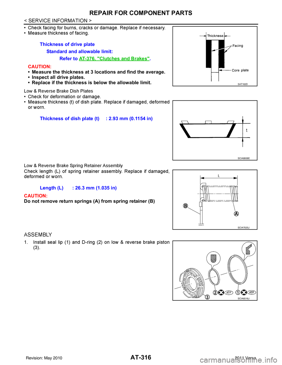
• Check facing for burns, cracks or damage. Replace if necessary.
• Measure thickness of facing.CAUTION:
• Measure the thickness at 3 locations and find the average.
• Inspect all drive plates.
• Replace if the thickness is below the allowable limit.
Low & Reverse Brake Dish Plates
• Check for deformation or damage.
• Measure thickness (t) of dish pl ate. Replace if damaged, deformed
or worn.
Low & Reverse Brake Spring Retainer Assembly
Check length (L) of spring retainer assembly. Replace if damaged,
deformed or worn.
CAUTION:
Do not remove return springs (A ) from spring retainer (B)
ASSEMBLY
1. Install seal lip (1) and D-ring (2) on low & reverse brake piston
(3).Thickness of drive plate
Standard and allowable limit: Refer to AT-376, "
Clutches and Brakes".
SAT162D
Thickness of dish plate (t) : 2.93 mm (0.1154 in)
SCIA8008E
Length (L) : 26.3 mm (1.035 in)
SCIA7025J
SCIA6516J
Revision: May 2010 2011 Versa
Page 335 of 3787
AT-318
< SERVICE INFORMATION >
REPAIR FOR COMPONENT PARTS
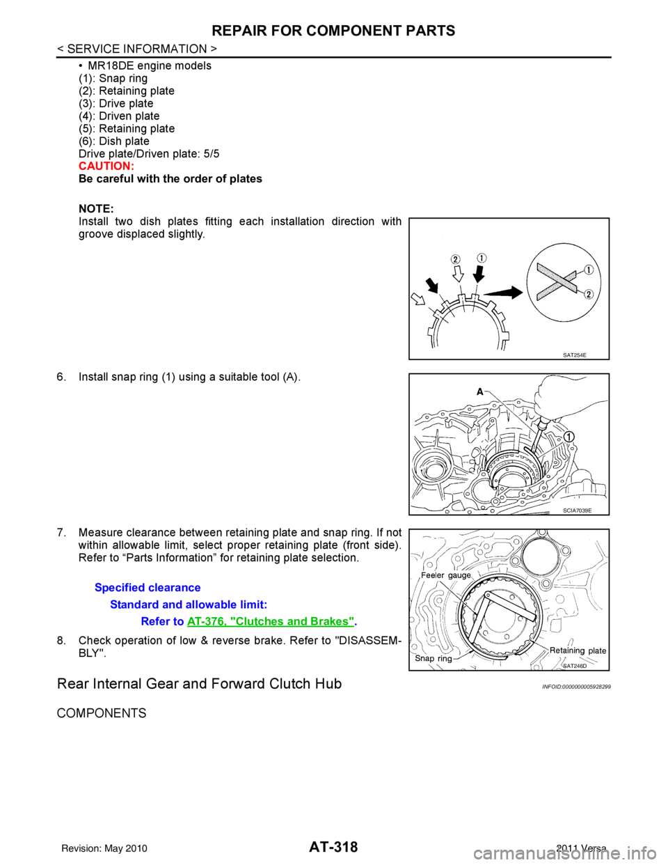
• MR18DE engine models
(1): Snap ring
(2): Retaining plate
(3): Drive plate
(4): Driven plate
(5): Retaining plate
(6): Dish plate
Drive plate/Driven plate: 5/5
CAUTION:
Be careful with the order of plates
NOTE:
Install two dish plates fitting each installation direction with
groove displaced slightly.
6. Install snap ring (1) using a suitable tool (A).
7. Measure clearance between retaining plate and snap ring. If not within allowable limit, select proper retaining plate (front side).
Refer to “Parts Information” for retaining plate selection.
8. Check operation of low & revers e brake. Refer to "DISASSEM-
BLY".
Rear Internal Gear and Forward Clutch HubINFOID:0000000005928299
COMPONENTS
SAT254E
SCIA7039E
Specified clearance
Standard and allowable limit: Refer to AT-376, "
Clutches and Brakes".
SAT246D
Revision: May 2010 2011 Versa
Page 393 of 3787

AT-376
< SERVICE INFORMATION >
SERVICE DATA AND SPECIFICATIONS (SDS)
Unit: mm (in)
AccumulatorINFOID:0000000005928316
RETURN SPRINGS
Unit: mm (in)
Unit: mm (in)
O-RINGS
Unit: mm (in)
Clutches and BrakesINFOID:0000000005928317
REVERSE CLUTCH
Locationspring designation Free length (l) Outer diameter (D)
Upper body L14 Pilot valve spring
38.98 (1.5346)8.9 (0.350)
L15 1–2 accumulator valve spring
20.5 (0.807)6.95 (0.2736)
1–2 accumulator piston spring 55.66 (2.1913)19.5 (0.768)
L16 1st reducing valve spring 27.0 (1.063)7.0 (0.276)
L17 3–2 timing valve spring 23.0 (0.906)6.65 (0.2618)
L18 Overrun clutch reducing valve spring37.5 (1.476)7.0 (0.276)
L19 Torque converter relief valve spring 33.3 (1.311)9.0 (0.354)
L20 Torque converter clutch control valve spring 53.01 (2.0870)6.5 (0.256)
L21 Cooler check valve spring 28.04 (1.1039)7.15 (0.2815)
Lower body L3 Pressure regulator valve spring
45.0 (1.772)15.0 (0.591)
L4 Overrun clutch control valve spring 21.7 (0.854)7.0 (0.276)
L5 Accumulator control valve spring 22.0 (0.866)6.5 (0.256)
L6 Shift valve A spring 21.7 (0.854)7.0 (0.276)
L7 Shuttle valve spring 51.0 (2.008)5.65 (0.2224)
L12 Shift valve B spring 21.7 (0.854)7.0 (0.276)
L13 Pressure modifier valve spring
32.0 (1.260)6.9 (0.272)
Pressure modifier piston spring 30.5 (1.201)9.8 (0.386)
— Line pressure relief valve spring 17.02 (0.6701)8.0 (0.315)
— Torque converter pressure holding spring 9.0 (0.354)7.3 (0.287)
Location Free length (L1)
Servo release accumulator 62.8 (2.472)
LocationLength (L2)
N-D accumulator 46.5 (1.831)
LocationInner diameter (Small) Inner diameter (Large)
Servo release accumulator 26.9 (1.059)44.2 (1.740)
N-D accumulator 34.6 (1.362)39.4 (1.551)
Number of drive plates 2
Number of driven plates 2
Drive plate thickness [mm (in)] Standard
2.0 (0.079)
Allowable limit 1.8 (0.071)
Driven plate thickness [mm (in)] Standard 2.0 (0.079)
Clearance [mm (in)] Standard
0.5 - 0.8 (0.020 - 0.031)
Allowable limit 1.2 (0.047)
Revision: May 2010 2011 Versa
Page 848 of 3787

BR-1
BRAKES
C
DE
G H
I
J
K L
M
SECTION BR
A
B
BR
N
O P
CONTENTS
BRAKE SYSTEM
SERVICE INFORMATION .. ..........................2
PRECAUTIONS .............................................. .....2
Precaution for Supplemental Restraint System
(SRS) "AIR BAG" and "SEAT BELT PRE-TEN-
SIONER" ............................................................. ......
2
Precaution Necessary for Steering Wheel Rota-
tion After Battery Disconnect ............................... ......
2
Precaution for Brake System ....................................3
PREPARATION ...................................................4
Special Service Tool ........................................... ......4
Commercial Service Tool ..........................................4
NOISE, VIBRATION AND HARSHNESS
(NVH) TROUBLESHOOTING .............................
5
NVH Troubleshooting Chart ................................ ......5
BRAKE PEDAL .............................................. .....6
Inspection and Adjustment .................................. ......6
Removal and Installation ...........................................7
BRAKE FLUID ................................................ .....9
On Board Inspection ........................................... ......9
Drain and Refill ..........................................................9
Bleeding Brake System .............................................9
BRAKE TUBE AND HOSE ................................11
Hydraulic Circuit .................................................. ....11
Front Brake Tube and Hose ....................................12
Rear Brake Tube and Hose ....................................12
Inspection After Installation .....................................13
DUAL PROPORTIONING VALVE .....................14
Removal and Installation .........................................14
Inspection ............................................................ ....14
BRAKE MASTER CYLINDER ........................ ....15
On-Board Inspection ........................................... ....15
Removal and Installation ..................................... ....15
Disassembly and Assembly .....................................16
BRAKE BOOSTER ...........................................20
On Board Inspection ............................................ ....20
Removal and Installation .........................................21
VACUUM LINES ...............................................23
Component ..............................................................23
Removal and Installation .........................................23
Inspection ................................................................23
FRONT DISC BRAKE .......................................25
On Board Inspection ............................................ ....25
Component ..............................................................25
Removal and Installation of Brake Pad ...................26
Removal and Installation of Brake Caliper Assem-
bly ........................................................................ ....
30
Disassembly and Assembly of Brake Caliper As-
sembly .....................................................................
31
Brake Burnishing Procedure ....................................34
REAR DRUM BRAKE .......................................35
Component .......................................................... ....35
Removal and Installation of Drum Brake Assembly
....
36
Removal and Installation of Wheel Cylinder ............39
Disassembly and Assembly of Wheel Cylinder .......39
SERVICE DATA AND SPECIFICATIONS
(SDS) .................................................................
40
General Specification ..............................................40
Brake Pedal .............................................................41
Check Valve ............................................................41
Brake Booster ..........................................................42
Front Disc Brake ......................................................42
Rear Drum Brake .....................................................42
Revision: May 2010 2011 Versa
Page 861 of 3787
BR-14
< SERVICE INFORMATION >
DUAL PROPORTIONING VALVE
DUAL PROPORTIONING VALVE
Removal and InstallationINFOID:0000000005928400
Removal
1. Remove the cowl top. Refer to EI-24, "Removal and Installation".
2. Disconnect brake lines from dual proportioning valve. • Mark brake lines for installation.
3. Remove dual proportioning valve bolt and dual proportioning valve.
4. Remove two bolts and bracket.
Installation
Installation is in the reverse order of removal.
• When installing brake lines to the dual proportioning valve, tighten to specifications. Refer to BR-11,
"Hydraulic Circuit".
InspectionINFOID:0000000005928401
CAUTION:
• Carefully monitor brake fluid level at master cylinder.
• Use the recommended new brake fluid. Refer to MA-14, "
Fluids and Lubricants".
• Be careful not to splash brake fluid on painted areas; it may cause paint damage. If brake fluid is
splashed on paint areas, wash it away with water immediately.
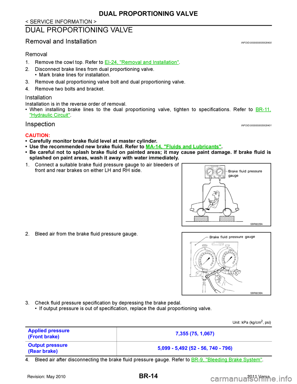
1. Connect a suitable brake fluid pressure gauge to air bleeders of front and rear brakes on either LH and RH side.
2. Bleed air from the brake fluid pressure gauge.
3. Check fluid pressure specific ation by depressing the brake pedal.
• If output pressure is out of specification, replace the dual proportioning valve.
Unit: kPa (kg/cm2, psi)
4. Bleed air after disconnecting the brake fluid pressure gauge. Refer to BR-9, "Bleeding Brake System".
SBR822BA
SBR823BA
Applied pressure
(Front brake) 7,355 (75, 1,067)
Output pressure
(Rear brake) 5,099 - 5,492 (52 - 56, 740 - 796)
Revision: May 2010
2011 Versa
Page 875 of 3787
BR-28
< SERVICE INFORMATION >
FRONT DISC BRAKE
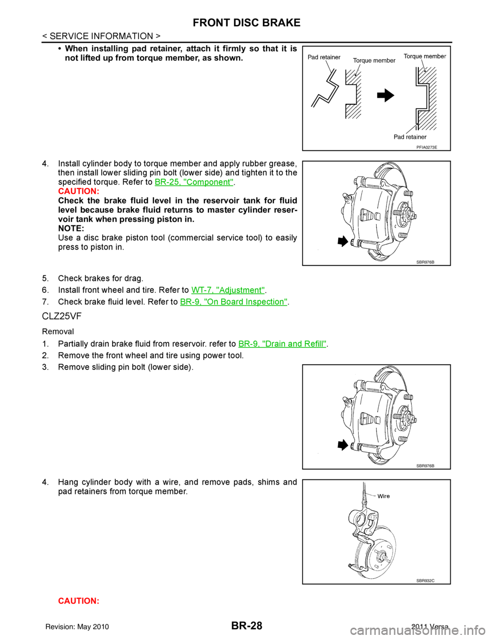
• When installing pad retainer, attach it firmly so that it isnot lifted up from torque member, as shown.
4. Install cylinder body to torque member and apply rubber grease, then install lower sliding pin bolt (lower side) and tighten it to the
specified torque. Refer to BR-25, "
Component".
CAUTION:
Check the brake fluid level in the reservoir tank for fluid
level because brake fluid returns to master cylinder reser-
voir tank when pressing piston in.
NOTE:
Use a disc brake piston tool (commercial service tool) to easily
press to piston in.
5. Check brakes for drag.
6. Install front wheel and tire. Refer to WT-7, "
Adjustment".
7. Check brake fluid level. Refer to BR-9, "
On Board Inspection".
CLZ25VF
Removal
1. Partially drain brake fluid from reservoir. refer to BR-9, "Drain and Refill".
2. Remove the front wheel and tire using power tool.
3. Remove sliding pin bolt (lower side).
4. Hang cylinder body with a wire, and remove pads, shims and pad retainers from torque member.
CAUTION:
PFIA0273E
SBR976B
SBR976B
SBR932C
Revision: May 2010 2011 Versa